


 Loading...
SuperStack® 3
Switch Implementation Guide
Generic guide for units in the SuperStack 3 Switch 4200 Series: 3C17300, 3C17302
http://www.3com.com/
Part No. DUA1730-0BAA01
Published April 2002
3Com Corporation 5400 Bayfront Plaza Santa Clara, California 95052-8145
Copyright © 2002, 3Com Technologies. All rights reserved. No part of this documentation may be reproduced in any form or by any means or used to make any derivative work (such as translation, transformation, or adaptation) without written permission from 3Com Technologies.
3Com Technologies reserves the right to revise this documentation and to make changes in content from time to time without obligation on the part of 3Com Technologies to provide notification of such revision or change.
3Com Technologies provides this documentation without warranty, term, or condition of any kind, either implied or expressed, including, but not limited to, the implied warranties, terms or conditions of merchantability, satisfactory quality, and fitness for a particular purpose. 3Com may make improvements or changes in the product(s) and/or the program(s) described in this documentation at any time.
If there is any software on removable media described in this documentation, it is furnished under a license agreement included with the product as a separate document, in the hard copy documentation, or on the removable media in a directory file named LICENSE.TXT or !LICENSE.TXT. If you are unable to locate a copy, please contact 3Com and a copy will be provided to you.
UNITED STATES GOVERNMENT LEGEND
If you are a United States government agency, then this documentation and the software described herein are provided to you subject to the following:
All technical data and computer software are commercial in nature and developed solely at private expense. Software is delivered as “Commercial Computer Software” as defined in DFARS 252.227-7014 (June 1995) or as a “commercial item” as defined in FAR 2.101(a) and as such is provided with only such rights as are provided in 3Com’s standard commercial license for the Software. Technical data is provided with limited rights only as provided in DFAR 252.227-7015 (Nov 1995) or FAR 52.227-14 (June 1987), whichever is applicable. You agree not to remove or deface any portion of any legend provided on any licensed program or documentation contained in, or delivered to you in conjunction with, this User Guide.
Unless otherwise indicated, 3Com registered trademarks are registered in the United States and may or may not be registered in other countries.
3Com and SuperStack are registered trademarks of 3Com Corporation. The 3Com logo and CoreBuilder are trademarks of 3Com Corporation.
Intel and Pentium are registered trademarks of Intel Corporation. Microsoft, MS-DOS, Windows, and Windows NT are registered trademarks of Microsoft Corporation. Novell and NetWare are registered trademarks of Novell, Inc. UNIX is a registered trademark in the United States and other countries, licensed exclusively through X/Open Company, Ltd. Solaris is a registered trademark of Sun Microsystems.
All other company and product names may be trademarks of the respective companies with which they are associated.
ENVIRONMENTAL STATEMENT
It is the policy of 3Com Corporation to be environmentally-friendly in all operations. To uphold our policy, we are committed to:
Establishing environmental performance standards that comply with national legislation and regulations.
Conserving energy, materials and natural resources in all operations.
Reducing the waste generated by all operations. Ensuring that all waste conforms to recognized environmental standards. Maximizing the recyclable and reusable content of all products.
Ensuring that all products can be recycled, reused and disposed of safely.
Ensuring that all products are labelled according to recognized environmental standards.
Improving our environmental record on a continual basis.
End of Life Statement
3Com processes allow for the recovery, reclamation and safe disposal of all end-of-life electronic components.
Regulated Materials Statement
3Com products do not contain any hazardous or ozone-depleting material.
Environmental Statement about the Documentation
The documentation for this product is printed on paper that comes from sustainable, managed forests; it is fully biodegradable and recyclable, and is completely chlorine-free. The varnish is environmentally-friendly, and the inks are vegetable-based with a low heavy-metal content.

CONTENTS
ABOUT THIS GUIDE
|
Conventions |
8 |
|
|
|
|
|
Related Documentation 9 |
|
|
|||
|
Documentation Comments |
9 |
|
|||
|
Product Registration |
10 |
|
|
||
1 |
|
|||||
SWITCH FEATURES OVERVIEW |
||||||
|
What is Management Software? |
13 |
||||
|
Switch Features Explained |
13 |
|
|||
|
Automatic IP Configuration |
14 |
||||
|
Port Security |
14 |
|
|
|
|
|
Aggregated Links |
14 |
|
|
||
|
Auto-negotiation |
14 |
|
|
||
|
Multicast Filtering |
15 |
|
|
||
|
Spanning Tree Protocol and Rapid Spanning Tree Protocol 16 |
|||||
|
Switch Database |
16 |
|
|
||
|
Traffic Prioritization |
16 |
|
|
||
|
RMON |
17 |
|
|
|
|
|
Broadcast Storm Control |
17 |
|
|||
|
VLANs |
18 |
|
|
|
|
2 |
|
|
||||
OPTIMIZING BANDWIDTH |
|
|||||
|
Port Features |
19 |
|
|
|
|
|
Duplex |
19 |
|
|
|
|
|
Flow Control |
20 |
|
|
|
|
|
Auto-negotiation |
20 |
|
|
||
|
Smart Auto-sensing |
20 |
|
|
||
|
Aggregated Links |
22 |
|
|
||
|
Aggregated Links and Your Switch 22 |
|||||
|
Aggregated Link Example |
25 |
||||

3 USING MULTICAST FILTERING
What is an IP Multicast? |
27 |
Benefits of Multicast |
28 |
Multicast Filtering 28
Multicast Filtering and Your Switch 29
IGMP Multicast Filtering 30
4 USING RESILIENCE FEATURES
Spanning Tree Protocol (STP) |
33 |
||
Rapid Spanning Tree Protocol (RSTP) 34 |
|||
What is STP? 34 |
|
|
|
How STP Works |
36 |
|
|
STP Requirements |
36 |
|
|
STP Calculation |
37 |
|
|
STP Configuration |
38 |
|
|
STP Reconfiguration |
38 |
|
|
How RSTP Differs to STP |
38 |
||
STP Example |
38 |
|
|
STP Configurations |
40 |
|
|
Default Behavior |
42 |
|
|
RSTP Default Behavior 42 |
|||
Fast Start Default Behavior |
42 |
||
Using STP on a Network with Multiple VLANs 42
5 USING THE SWITCH DATABASE
|
What is the Switch Database? |
45 |
|
How Switch Database Entries Get Added 45 |
|
|
Switch Database Entry States |
46 |
|
|
|
6 USING TRAFFIC PRIORITIZATION |
||
|
What is Traffic Prioritization? |
47 |
|
How Traffic Prioritization Works |
48 |
|
802.1D traffic classification |
48 |
|
DiffServ traffic classification |
49 |
Traffic Prioritization and your Switch 50

7 STATUS MONITORING AND STATISTICS
|
RMON 53 |
|
|
|
|
What is RMON? |
53 |
|
|
|
The RMON Groups |
54 |
|
|
|
Benefits of RMON |
54 |
|
|
|
RMON and the Switch |
55 |
|
|
|
Alarm Events |
56 |
|
|
|
The Default Alarm Settings |
56 |
||
|
The Audit Log |
57 |
|
|
|
Email Notification of Events |
57 |
||
|
Hardware Status Monitoring |
58 |
||
|
|
|||
8 SETTING UP VIRTUAL LANS |
||||
|
What are VLANs? |
61 |
|
|
|
Benefits of VLANs |
62 |
|
|
|
VLANs and Your Switch |
63 |
|
|
|
|
The Default VLAN |
63 |
|
|
|
|
Creating New VLANs |
63 |
|
|
|
|
VLANs: Tagged and Untagged Membership 64 |
||||
|
Placing a Port in a Single VLAN |
64 |
|
||
|
Connecting VLANS to Other VLANS |
65 |
|||
|
VLAN Configuration Examples |
66 |
|
|
|
|
Using Untagged Connections |
66 |
|
||
|
Using 802.1Q Tagged Connections |
67 |
|||
|
|
||||
9 USING AUTOMATIC IP CONFIGURATION |
|||||
|
How Your Switch Obtains IP Information |
70 |
|||
|
How Automatic IP Configuration Works |
70 |
|||
|
Automatic Process |
71 |
|
|
|
|
Important Considerations 72 |
|
|
|
|
|
Server Support 72 |
|
|
|
|
|
Event Log Entries and Traps |
72 |
|
|
|
|
|
|
|
|
|
A CONFIGURATION RULES |
|
|
|
||
|
Configuration Rules for Gigabit Ethernet |
75 |
|||
|
Configuration Rules for Fast Ethernet |
76 |
|||

|
Configuration Rules with Full Duplex |
77 |
|
|
|
B NETWORK CONFIGURATION EXAMPLES |
||
|
Simple Network Configuration Examples |
80 |
|
Segmentation Switch Example 80 |
|
|
Collapsed Backbone Switch Example |
81 |
|
Desktop Switch Example 82 |
|
|
Advanced Network Configuration Examples |
83 |
|
|
Improving the Resilience of Your Network |
83 |
|
|
Enhancing the Performance of Your Network 84 |
||
|
|
|
|
C IP ADDRESSING |
|
|
|
|
IP Addresses 85 |
|
|
|
Simple Overview |
85 |
|
|
Advanced Overview 86 |
|
|
|
Subnets and Subnet Masks 88 |
|
|
|
Default Gateways |
90 |
|
GLOSSARY
INDEX

ABOUT THIS GUIDE
This guide describes the features of the SuperStack® 3 Switch 4200 Series and outlines how to use these features to optimize the performance of your network.
This guide is intended for the system or network administrator who is responsible for configuring, using, and managing the Switches. It assumes a working knowledge of local area network (LAN) operations and familiarity with communication protocols that are used to interconnect LANs.
For detailed descriptions of the web interface operations and the command line interface (CLI) commands that you require to manage the Switch please refer to the Management Interface Reference Guide supplied in HTML format on the CD-ROM that accompanies your Switch.
If release notes are shipped with your product and the information there differs from the information in this guide, follow the instructions in the release notes.
Most user guides and release notes are available in Adobe Acrobat Reader Portable Document Format (PDF) or HTML on the 3Com World Wide Web site:
http://www.3com.com/
8 ABOUT THIS GUIDE
Conventions |
Table 1 and Table 2 list conventions that are used throughout this guide. |
||||
|
Table 1 |
Notice Icons |
|
|
|
|
|
|
|
|
|
|
Icon |
Notice Type |
Description |
||
|
|
|
|
||
|
|
Information note Information that describes important features or |
|||
|
|
|
|
instructions |
|
|
|
Caution |
|
Information that alerts you to potential loss of data or |
|
|
|
|
|
potential damage to an application, system, or device |
|
|
|
Warning |
|
Information that alerts you to potential personal injury |
|
|
|
|
|
||
|
Table 2 |
Text Conventions |
|||
|
|
|
|
||
|
Convention |
Description |
|||
|
|
|
|||
|
Screen displays |
This typeface represents information as it appears on the |
|
||
|
|
|
screen. |
||
|
|
|
|
|
|
|
Syntax |
|
The word “syntax” means that you must evaluate the syntax |
||
|
|
|
provided and then supply the appropriate values for the |
||
|
|
|
placeholders that appear in angle brackets. Example: |
||
|
|
|
To change your password, use the following syntax: |
||
|
|
|
|
system password <password> |
|
|
|
|
In this example, you must supply a password for <password>. |
||
|
|
|
|
||
|
Commands |
The word “command” means that you must enter the |
|||
|
|
|
command exactly as shown and then press Return or Enter. |
||
|
|
|
Commands appear in bold. Example: |
||
|
|
|
To display port information, enter the following command: |
||
|
|
|
|
bridge port detail |
|
|
|
|
|
||
|
The words “enter” |
When you see the word “enter” in this guide, you must type |
|||
|
and “type” |
something, and then press Return or Enter. Do not press |
|||
|
|
|
Return or Enter when an instruction simply says “type.” |
||
|
|
|
|
||
|
Keyboard key names |
If you must press two or more keys simultaneously, the key |
|||
|
|
|
names are linked with a plus sign (+). Example: |
||
|
|
|
|
Press Ctrl+Alt+Del |
|
|
|
|
|||
|
Words in italics |
Italics are used to: |
|
||
|
|
|
■ |
Emphasize a point. |
|
|
|
|
■ Denote a new term at the place where it is defined in the |
||
|
|
|
|
text. |
|
■ Identify menu names, menu commands, and software button names. Examples:
From the Help menu, select Contents.
Click OK.

Related Documentation |
9 |
Related |
In addition to this guide, each Switch documentation set includes the |
|
Documentation |
following: |
|
|
■ |
Getting Started Guide |
|
|
This guide contains: |
|
|
■ all the information you need to install and set up the Switch in its |
|
|
default state |
|
|
■ information on how to access the management software to begin |
|
|
managing the Switch. |
|
■ Management Interface Reference Guide |
|
|
|
This guide contains information about the web interface operations |
|
|
and CLI (command line interface) commands that enable you to |
|
|
manage the Switch. It contains an explanation for each command and |
|
|
the different parameters available. It is supplied in HTML format on |
|
|
the CD-ROM that accompanies your Switch. |
|
■ Management Quick Reference Guide |
|
|
|
This guide contains: |
|
|
■ A list of the features supported by the Switch |
|
|
■ A summary of the web interface operations and CLI commands |
|
|
that enable you to manage the Switch. |
|
■ |
Release Notes |
|
|
These notes provide information about the current software release, |
|
|
including new features, modifications, and known problems. |
|
In addition, there are other publications you may find useful: |
|
|
■ Online documentation accompanying the 3Com Network Supervisor |
|
|
|
application that is supplied on the CD-ROM that accompanies your |
|
|
Switch. |
|
■ Documentation accompanying the Advanced Redundant Power |
|
|
|
System. |
|
|
|
Documentation |
Your suggestions are very important to us. They will help make our |
|
Comments |
documentation more useful to you. Please e-mail comments about this |
|
|
document to 3Com at: |
|
pddtechpubs_comments@3com.com

10 ABOUT THIS GUIDE
Please include the following information when contacting us:
■Document title
■Document part number (on the title page)
■Page number (if appropriate)
Example:
■SuperStack 3 Switch Implementation Guide
■Part number: DUA1730-0BAA0x
■Page 25
Please note that we can only respond to comments and questions about 3Com product documentation at this e-mail address. Questions related to technical support or sales should be directed in the first instance to your network supplier.
Product |
You can now register your SuperStack 3 Switch on the 3Com web site: |
Registration |
http://support.3com.com/registration/frontpg.pl |
|
I |
SWITCH FEATURES |
|
Chapter 1 Switch Features Overview
Chapter 2 Optimizing Bandwidth
Chapter 3 Using Multicast Filtering
Chapter 4 Using Resilience Features
Chapter 5 Using the Switch Database
Chapter 6 Using Traffic Prioritization
Chapter 7 Status Monitoring and Statistics
Chapter 8 Setting Up Virtual LANs
Chapter 9 Using Automatic IP Configuration
12

1 |
SWITCH FEATURES OVERVIEW |
|
|
This chapter contains introductory information about the SuperStack® 3 |
|
Switch management software and supported features. It covers the |
|
following topics: |
|
■ What is Management Software? |
|
■ Switch Features Explained |
|
For detailed descriptions of the web interface operations and the |
|
command line interface (CLI) commands that you require to manage the |
|
Switch please refer to the Management Interface Reference Guide |
|
supplied in HTML format on the CD-ROM that accompanies your Switch. |
|
|
What is |
Your Switch can operate in its default state. However, to make full use of |
Management |
the features offered by the Switch, and to change and monitor the way it |
Software? |
works, you have to access the management software that resides on the |
|
Switch. This is known as managing the Switch. |
|
Managing the Switch can help you to improve its efficiency and therefore |
|
the overall performance of your network. |
|
There are several different methods of accessing the management |
|
software to manage the Switch. These methods are explained in |
|
Chapter 3 of the Getting Started Guide that accompanies your Switch. |
|
|
Switch Features |
The management software provides you with the capability to change the |
Explained |
default state of some of the Switch features. This section provides a brief |
|
overview of these features — their applications are explained in more |
|
detail later in this guide. |
For a list of the features supported by your Switch, please refer to the Management Quick Reference Guide that accompanies your Switch.

14 CHAPTER 1: SWITCH FEATURES OVERVIEW
Automatic IP By default the Switch tries to configure itself with IP information without Configuration requesting user intervention. It uses the following industry standard
methods to allocate the Switch IP information:
■Dynamic Host Configuration Protocol (DHCP)
■Auto-IP — the Switch will configure itself with its default IP address 169.254.100.100 if it is operating in a standalone mode, and/or no other Switches on the network have this IP address. If this default IP address is already in use on the network then the Switch detects this and configures itself with an IP address in the range 169.254.1.0 to 169.254.254.255.
■Bootstrap Protocol (BOOTP)
For ease of use, you do not have to choose between these three automatic configuration methods. The Switch tries each method in a specified order.
For more information about how the automatic IP configuration feature works, see Chapter 9 “Using Automatic IP Configuration”.
Port Security Port security guards against unauthorized users connecting devices to your network. The port security feature, Disconnect Unauthorised Device (DUD), disables a port if an unauthorised device transmits data on it.
Aggregated Links Aggregated links are connections that allow devices to communicate using up to two links in parallel. On the Switch 4200, aggregated links are only supported on the 10/100/1000 Mbps ports. Aggregated links provide two benefits:
■They can potentially double the bandwidth of a connection.
■They can provide redundancy — if one link is broken, the other link can share the traffic for that link.
For more information about aggregated links, see Chapter 2 “Optimizing Bandwidth”.
Auto-negotiation Auto-negotiation allows ports to auto-negotiate port speed, duplex-mode (only at 10 Mbps and 100 Mbps) and flow control. When auto-negotiation is enabled (default), a port “advertises” its maximum capabilities — these capabilities are by default the parameters that provide the highest performance supported by the port.

Switch Features Explained |
15 |
For details of the auto-negotiation features supported by your Switch, please refer to the Getting Started Guide that accompanies your Switch.
Ports operating at 1000 Mbps only support full duplex mode.
Duplex
Full duplex mode allows packets to be transmitted and received simultaneously and, in effect, doubles the potential throughput of a link.
Flow Control
All Switch ports support flow control, which is a mechanism that minimizes packet loss during periods of congestion on the network.
Flow control is supported on ports operating in half duplex mode, and is implemented using the IEEE 802.3x standard on ports operating in full duplex mode.
Smart Auto-sensing
Smart auto-sensing allows auto-negotiating multi-speed ports, such as 10/100 Mbps or 10/100/1000 Mbps, to monitor and detect high error rates, or problems in the “physical” interconnection to another port. The port reacts accordingly by tuning the link from its higher speed to the lower supported speed to provide an error-free connection to the network.
For more information about auto-negotiation and port capabilities, see
Chapter 2 “Optimizing Bandwidth”.
Multicast Filtering Multicast filtering allows the Switch to forward multicast traffic to only the endstations that are part of a predefined multicast group, rather than broadcasting the traffic to the whole network.
The multicast filtering system supported by your Switch uses IGMP (Internet Group Management Protocol) snooping to detect the endstations in each multicast group to which multicast traffic should be forwarded.
For more information about multicast filtering, see Chapter 3 “Using
Multicast Filtering”.

16 CHAPTER 1: SWITCH FEATURES OVERVIEW
Spanning Tree Spanning Tree Protocol (STP) and Rapid Spanning Tree Protocol (RSTP) Protocol and Rapid are bridge-based systems that makes your network more resilient to
Spanning Tree link failure and also provides protection from network loops — one of Protocol the major causes of broadcast storms.
STP allows you to implement alternative paths for network traffic in the event of path failure and uses a loop-detection process to:
■Discover the efficiency of each path.
■Enable the most efficient path.
■Disable the less efficient paths.
■Enable one of the less efficient paths if the most efficient path fails.
RSTP is an enhanced version of the STP feature and is enabled by default.
RSTP can restore a network connection quicker than the STP feature.
STP conforms to the IEEE 802.1D-1998 standard, and RSTP conforms to the IEEE 802.1w standard.
For more information about STP and RSTP, see Chapter 4 “Using
Resilience Features”.
Switch Database The Switch Database is an integral part of the Switch and is used by the Switch to determine if a packet should be forwarded, and which port should transmit the packet if it is to be forwarded.
For more information about the Switch Database, see Chapter 5 “Using the Switch Database”.
Traffic Prioritization Traffic prioritization allows your network traffic to be prioritized to ensure that high priority data, such as time-sensitive and system-critical data is transferred smoothly and with minimal delay over a network.
Traffic prioritization ensures that high priority data is forwarded through the Switch without being delayed by lower priority data. Traffic prioritization uses the two traffic queues that are present in the hardware of the Switch to ensure that high priority traffic is forwarded on a different queue from lower priority traffic. High priority traffic is given preference over low priority traffic to ensure that the most critical traffic gets the highest level of service.

Switch Features Explained |
17 |
This system is compatible with the relevant sections of the IEEE 802.1D/D17 standard (incorporating IEEE 802.1p).
For more information about 802.1D and traffic prioritization, see Chapter 6 “Using Traffic Prioritization”.
Quality of Service
Traffic prioritization can be taken one step further by using the Quality of Service (QoS) feature. Quality of Service (QoS) enables you to specify service levels for different traffic classifications. This enables you to prioritize particular applications or traffic types.
The Switch uses a policy-based QoS mechanism. By default, all traffic is assigned the "normal" QoS policy profile. If needed, you can create other QoS policy profiles and apply them to different traffic types so that they have different priorities across the network.
For more information about Quality of Service, see Chapter 6 “Using
Traffic Prioritization”.
RMON Remote Monitoring (RMON) is an industry standard feature for traffic monitoring and collecting network statistics. The Switch software continually collects statistics about the LAN segments connected to the Switch. If you have a management workstation with an RMON management application, the Switch can transfer these statistics to your workstation on request or when a pre-defined threshold is exceeded.
Event Notification
You can configure your Switch to send you notification when certain events occur. You can receive notification via email, SMS (Short Message Server), or pager.
For more information about RMON and Event Notification, see Chapter 7 “Status Monitoring and Statistics”.
Broadcast Storm Broadcast Storm Control is a system that monitors the level of broadcast
Control traffic on that port. If the broadcast traffic level rises to a pre-defined number of frames per second (threshold), the broadcast traffic on the port is blocked until the broadcast traffic level drops below the threshold. This system prevents the overwhelming broadcast traffic that can result from network equipment which is faulty or configured incorrectly.

18 CHAPTER 1: SWITCH FEATURES OVERVIEW
VLANs A Virtual LAN (VLAN) is a flexible group of devices that can be located anywhere in a network, but which communicate as if they are on the same physical segment. With VLANs, you can segment your network without being restricted by physical connections — a limitation of traditional network design. As an example, with VLANs you can segment your network according to:
■Departmental groups
■Hierarchical groups
■Usage groups
For more information about VLANs, see Chapter 8 “Setting Up Virtual
LANs”.

2 |
OPTIMIZING BANDWIDTH |
|
There are many ways you can optimize the bandwidth on your network and improve network performance. If you utilize certain Switch features you can provide the following benefits to your network and end users:
|
■ |
Increased bandwidth |
|
■ |
Quicker connections |
|
■ Faster transfer of data |
|
|
■ |
Minimized data errors |
|
■ |
Reduced network downtime |
|
For detailed descriptions of the web interface operations and the |
|
|
command line interface (CLI) commands that you require to manage the |
|
|
Switch please refer to the Management Interface Reference Guide |
|
|
supplied in HTML format on the CD-ROM that accompanies your Switch. |
|
|
|
|
Port Features |
The default state for all the features detailed below provides the best |
|
|
configuration for a typical user. In normal operation, you do not need to |
|
|
alter the Switch from its default state. However, under certain conditions |
|
|
you may wish to alter the default state of these ports, for example, if you |
|
|
want to force a port to operate at 10 Mbps. |
|
Duplex Full duplex allows packets to be transmitted and received simultaneously and, in effect, doubles the potential throughput of a link. Half duplex only allows packets to be transmitted or received at any one time.
To communicate effectively, both devices at either end of a link must use the same duplex mode. If the devices at either end of a link support auto-negotiation, this is done automatically.

20 CHAPTER 2: OPTIMIZING BANDWIDTH
If the devices at either end of a link do not support auto-negotiation, both ends must be manually set to full duplex or half duplex accordingly.
Ports operating at 1000 Mbps support full duplex mode only.
Flow Control All Switch ports support flow control, which is a mechanism that minimizes packet loss during periods of congestion on the network. Packet loss is caused by one or more devices sending traffic to an already overloaded port on the Switch. Flow control minimizes packet loss by inhibiting the transmitting port from generating more packets until the period of congestion ends.
Flow control is supported on ports operating in half duplex mode, and is implemented using the IEEE 802.3x standard on ports operating in full duplex mode.
Auto-negotiation Auto-negotiation allows ports to auto-negotiate port speed, duplex-mode (only at 10 Mbps and 100 Mbps) and flow control. When auto-negotiation is enabled (default), a port “advertises” its maximum capabilities — these capabilities are by default the parameters that provide the highest performance supported by the port.
You can disable auto-negotiation on all fixed ports on the Switch, or on a per port basis. You can also modify the capabilities that a port “advertises” on a per port basis, dependent on the type of port.
For auto-negotiation to work, ports at both ends of the link must be set to auto-negotiate.
Ports operating at 1000 Mbps support full duplex mode only.
If auto-negotiation is disabled, the ports will no longer operate in auto-MDIX mode. Therefore, if you wish to disable auto-negotiation you must ensure you have the correct type of cable, that is cross-over or straight-through, for the type of device you are connecting to. For more information on suitable cable types, please refer to the Getting Started Guide that accompanies your Switch.
Smart Auto-sensing Smart auto-sensing allows auto-negotiating multi-speed ports, such as 10/100 Mbps or 10/100/1000 Mbps, to monitor and detect a high error rate on a link, or a problem in the “physical” interconnection to another
Port Features |
21 |
port and react accordingly. In other words, auto-negotiation may “agree” upon a configuration that the cable cannot sustain; smart auto-sensing can detect this and adjust the link accordingly.
For example, smart auto-sensing can detect network problems, such as an unacceptably high error rate or a poor quality cable. If both ends of the link support 100/1000 Mbps auto-negotiation, then auto-sensing tunes the link to 100 Mbps to provide an error-free 100 Mbps connection to the network.
An SNMP Trap is sent every time a port is down-rated to a lower speed.
Conditions that affect smart auto-sensing:
■Smart auto-sensing will not operate on links that do not support auto-negotiation, or on links where one end is at a fixed speed. The link will reset to the higher speed of operation when the link is lost or the unit is power cycled.
■Smart auto-sensing can only be configured per unit and not on a per port basis.
22 CHAPTER 2: OPTIMIZING BANDWIDTH
Aggregated Links Aggregated links are connections that allow devices to communicate using up to two links in parallel. Aggregated links are supported on the 10/100/1000BASE-T ports only. These parallel links provide two benefits:
■They can potentially double the bandwidth of a connection.
■They can provide redundancy — if one link is broken, the other link can share the traffic for that link.
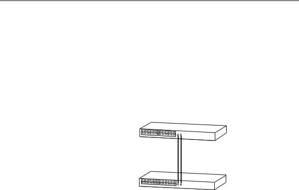
Figure 1 shows two Switches connected using an aggregated link containing two member links. If the ports on both Switch units are configured as 1000BASE-T and they are operating in full duplex, the potential maximum bandwidth of the connection is 2 Gbps.
Figure 1 Switch units connected using an aggregated link
.
Switch
 Aggregated Link
Switch
Aggregated Links and Each Switch supports up to two aggregated links. Each aggregated link Your Switch can support up to two member links.
When setting up an aggregated link, note that:
■The ports at both ends of a member link must be configured as members of an aggregated link.
■A member link port can only belong to one aggregated link.
■The member link ports can have different port configurations within the same aggregated link, that is, auto-negotiation, port speed, and duplex mode. However, please note the following:
■To be an active participant in an aggregated link the member link ports must operate in full duplex mode. (If a member link port does not operate in full duplex mode it can still be a member of an aggregated link but it will never be activated.)

Aggregated Links |
23 |
■If ports of a different speed are aggregated together, the higher speed links carry the traffic. The lower speed links only carry the traffic if the higher speed links fail.
■The aggregated link does not support security.
■Member links must retain the same groupings at both ends of an aggregated link. For example, the configuration in Figure 2 will not work as Switch A has one aggregated link defined whose member links are then split between two aggregated links defined on Switches B and C.
Figure 2 An illegal aggregated link configuration
Switch A
AL 1
Switch B
AL 2
Switch C
AL 3
When using an aggregated link, note that:
■To gather statistics about an aggregated link, you must add together the statistics for each port in the aggregated link.
■If you wish to disable a single member link of an aggregated link, you must first physically remove the connection to ensure that you do not lose any traffic, before you disable both ends of the member link separately. If you do this, the traffic destined for that link is distributed to the other links in the aggregated link.
If you do not remove the connection and only disable one end of the member link port, traffic is still forwarded to that port by the aggregated link port at the other end. This means that a significant amount of traffic may be lost.
■Before removing all member links from an aggregated link, you must disable all the aggregated link member ports or disconnect all the links, except one — if you do not, a loop may be created.
24 CHAPTER 2: OPTIMIZING BANDWIDTH
Traffic Distribution and Link Failure on Aggregated Links
To maximize throughput, all traffic is distributed across the individual links that make up an aggregated link. Therefore, when a packet is made available for transmission down an aggregated link, a hardware-based traffic distribution mechanism determines which particular port in the link should be used; this mechanism uses the MAC address. The traffic is distributed among the member links as efficiently as possible.
To avoid the potential problem of out-of-sequence packets (or “packet re-ordering”), the Switch ensures that all the conversations between a given pair of endstations will pass through the same port in the aggregated link. Single-to-multiple endstation conversations, on the other hand, may still take place over different ports.
If the link state on any of the ports in an aggregated link becomes inactive due to link failure, then the Switch will automatically redirect the aggregated link traffic to the remaining ports. Aggregated links therefore provide built-in resilience for your network.
The Switch also has a mechanism to prevent the possible occurrence of packet re-ordering when a link recovers too soon after a failure.
Aggregated Links |
25 |
Aggregated Link The example shown in Figure 3 illustrates an 2 Gbps aggregated link Example between two Switch units.
Figure 3 A 2 Gbps aggregated link between two Switch units
Switch
2 Gbps Aggregated Link
Switch
To set up this configuration:
1Add the 1000BASE-T ports on the upper unit to the aggregated link.
2Add the 1000BASE-T ports on the lower unit to the aggregated link.
3Connect the 1000BASE-T port marked ‘Up’ on the upper Switch to the 1000BASE-T port marked ‘Up’ on the lower Switch.
4Connect the 1000BASE-T port marked ‘Down’ on the upper Switch to the 1000BASE-T port marked ‘Down’ on the lower Switch.
26 CHAPTER 2: OPTIMIZING BANDWIDTH

3 |
USING MULTICAST FILTERING |
|
Multicast filtering improves the performance of networks that carry multicast traffic.
This chapter explains multicasts, multicast filtering, and how multicast filtering can be implemented on your Switch. It covers the following topics:
|
■ What is an IP Multicast? |
|
|
■ |
Multicast Filtering |
|
■ |
IGMP Multicast Filtering |
|
For detailed descriptions of the web interface operations and the |
|
|
command line interface (CLI) commands that you require to manage the |
|
|
Switch please refer to the Management Interface Reference Guide |
|
|
supplied in HTML format on the CD-ROM that accompanies your Switch. |
|
|
|
|
What is an IP |
A multicast is a packet that is intended for “one-to-many” and “many- |
|
Multicast? |
to-many” communication. Users explicitly request to participate in the |
|
|
communication by joining an endstation to a specific multicast group. If |
|
|
the network is set up correctly, a multicast can only be sent to an |
|
|
endstation or a subset of endstations in a LAN, or VLAN, that belong to |
|
|
the relevant multicast group. |
|
Multicast group members can be distributed across multiple subnetworks; thus, multicast transmissions can occur within a campus LAN or over a WAN. In addition, networks that support IP multicast send only one copy of the desired information across the network until the delivery path that reaches group members diverges. It is only at these points that multicast packets are replicated and forwarded, which makes efficient use of network bandwidth.

28 CHAPTER 3: USING MULTICAST FILTERING
A multicast packet is identified by the presence of a multicast group address in the destination address field of the packet’s IP header.
Benefits of Multicast The benefits of using IP multicast are that it:
■Enables the simultaneous delivery of information to many receivers in the most efficient, logical way.
■Reduces the load on the source (for example, a server) because it does not have to produce multiple copies of the same data.
■Makes efficient use of network bandwidth and scales well as the number of participants or collaborators expands.
■Works with other IP protocols and services, such as Quality of Service (QoS).
There are situations where a multicast approach is more logical and efficient than a unicast approach. Application examples include distance learning, transmitting stock quotes to brokers, and collaborative computing.
A typical use of multicasts is in video-conferencing, where high volumes of traffic need to be sent to several endstations simultaneously, but where broadcasting that traffic to all endstations would seriously reduce network performance.
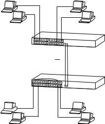
Multicast Filtering Multicast filtering is the process that ensures that endstations only receive multicast traffic if they register to join specific multicast groups. With multicast filtering, network devices only forward multicast traffic to the ports that are connected to registered endstations.
Figure 4 shows how a network behaves without multicast filtering and with multicast filtering.

Multicast Filtering |
29 |
Figure 4 The effect of multicast filtering
Multicast Filtering Your Switch provides automatic multicast filtering support using IGMP and Your Switch (Internet Group Management Protocol) Snooping. It also supports IGMP
query mode.
Snooping Mode
Snooping Mode allows your Switch to forward multicast packets only to the appropriate ports. The Switch “snoops” on exchanges between endstations and an IGMP device, typically a router, to find out the ports that wish to join a multicast group and then sets its filters accordingly
Query Mode
Query mode allows the Switch to function as the Querier if it has the lowest IP address in the subnetwork to which it belongs.
IGMP querying is disabled by default on the Switch 4200. This helps prevent interoperability issues with core products that may not follow the lowest IP address election method.
You can enable or disable IGMP query mode for all Switch units in the stack using the queryMode command on the command line interface IGMP menu.
You would enable query mode if you wish to run multicast sessions in a network that does not contain any IGMP routers (or queriers). This

30 CHAPTER 3: USING MULTICAST FILTERING
|
command will configure the Switch 4200 Series to automatically |
|
negotiate with compatible devices on VLAN 1 to become the querier. |
|
The Switch 4200 Series is compatible with any device that conforms to |
|
the IGMP v2 protocol. |
|
|
IGMP Multicast |
IGMP is the system that all IP-supporting network devices use to register |
Filtering |
endstations with multicast groups. It can be used on all LANs and VLANs |
|
that contain a multicast capable IP router and on other network devices |
|
that support IP. |
IGMP multicast filtering works as follows:
1The IP router (or querier) periodically sends query packets to all the endstations in the LANs or VLANs that are connected to it.
If your network has more than one IP router, then the one with the lowest IP address becomes the querier. The Switch can be the IGMP querier and will become so if its own IP address is lower than that of any other IGMP queriers connected to the LAN or VLAN. However, as the Switch only has an IP address on its default VLAN, the Switch will only ever query on the default VLAN (VLAN1). Therefore, if there are no other queriers on other VLANs, the IP multicast traffic will not be forwarded on them.
2When an IP endstation receives a query packet, it sends a report packet back that identifies the multicast group that the endstation would like to join.
3When the report packet arrives at a port on a Switch with IGMP multicast learning enabled, the Switch learns that the port is to forward traffic for the multicast group and then forwards the packet to the router.
4When the router receives the report packet, it registers that the LAN or VLAN requires traffic for the multicast groups.
5When the router forwards traffic for the multicast group to the LAN or VLAN, the Switch units only forward the traffic to ports that received a report packet.
Enabling IGMP Multicast Learning
You can enable or disable multicast learning and IGMP querying using the snoopMode command on the CLI or the web interface. For more information about enabling IGMP multicast learning, please refer to the Management Interface Reference Guide supplied on your Switch CD-ROM.
Loading...