


11 Mbps Wireless LAN
Access Point 8000
User Guide
Version 1.1
http://www.3com.com/
http://support.3com.com/registration/frontpg.pl/
Published April, 2002
Version 1.1.2
3Com Corporation |
Copyright © 2002 3Com Corporation. All rights reserved. No part of this documentation may be |
5400 Bayfront Plaza |
reproduced in any form or by any means or used to make any derivative work (such as translation, |
Santa Clara, California |
transformation, or adaptation) without written permission from 3Com Corporation. |
95052-8145 |
3Com Corporation reserves the right to revise this documentation and to make changes in content from time |
|
|
|
to time without obligation on the part of 3Com Corporation to provide notification of such revision or change. |
|
3Com Corporation provides this documentation without warranty, term, or condition of any kind, either |
|
implied or expressed, including, but not limited to, the implied warranties, terms or conditions of |
|
merchantability, satisfactory quality, and fitness for a particular purpose. 3Com may make improvements or |
|
changes in the product(s) and/or the program(s) described in this documentation at any time. |
|
If there is any software on removable media described in this documentation, it is furnished under a license |
|
agreement included with the product as a separate document, in the hard copy documentation, or on the |
|
removable media in a directory file named LICENSE.TXT or !LICENSE.TXT. If you are unable to locate a copy, |
|
please contact 3Com and a copy will be provided to you. |
|
UNITED STATES GOVERNMENT LEGEND |
|
If you are a United States government agency, then this documentation and the software described herein |
|
are provided to you subject to the following: |
|
All technical data and computer software are commercial in nature and developed solely at private expense. |
|
Software is delivered as “Commercial Computer Software” as defined in DFARS 252.227-7014 (June 1995) |
|
or as a “commercial item” as defined in FAR 2.101(a) and as such is provided with only such rights as are |
|
provided in 3Com’s standard commercial license for the Software. Technical data is provided with limited |
|
rights only as provided in DFAR 252.227-7015 (Nov 1995) or FAR 52.227-14 (June 1987), whichever is |
|
applicable. You agree not to remove or deface any portion of any legend provided on any licensed program |
|
or documentation contained in, or delivered to you in conjunction with, this User Guide. |
|
Unless otherwise indicated, 3Com registered trademarks are registered in the United States and may or may |
|
not be registered in other countries. |
|
3Com and the 3Com logo are registered trademarks and AirConnect is a trademark of 3Com Corporation. |
|
Wi-Fi is a trademark of the Wireless Ethernet Compatibility Alliance. |
|
All other company and product names may be trademarks of the respective companies with which they |
|
are associated. |
|
EXPORT RESTRICTIONS: This product contains Encryption and may require US and/or Local Government |
|
authorization prior to export or import to another country. |

CONTENTS
1 |
INTRODUCTION |
|
|
|
|
|
|
Wireless and Wired Networks |
1 |
|
|||
|
Access Point 8000 Feature Summary |
1 |
||||
|
Installation Overview |
2 |
|
|
|
|
|
|
|
||||
2 INSTALLING THE ACCESS POINT |
|
|||||
|
Before You Begin 5 |
|
|
|
|
|
|
Deciding Where to Place Equipment |
5 |
||||
|
Connecting the Standard Antenna 6 |
|
||||
|
Placing the Access Point |
6 |
|
|
||
|
Mounting on a Wall |
7 |
|
|
||
|
Mounting on a Ceiling |
8 |
|
|
||
|
Connecting Power |
9 |
|
|
|
|
|
Connecting to an Ethernet Network |
10 |
||||
|
Checking the LEDs |
10 |
|
|
|
|
|
Selecting A Different Antenna |
11 |
|
|||
|
Omnidirectional Antenna |
11 |
|
|||
|
Ceiling Mount Omnidirectional Antenna 12 |
|||||
|
Ceiling Mount Hallway Antenna |
12 |
||||
|
Directional Panel Antenna |
13 |
|
|||
|
Connecting an Optional Antenna |
13 |
||||
|
Installing Software Utilities |
14 |
|
|
||
3 |
|
|
|
|||
ACCESS POINT SECURITY |
|
|
||||
|
Upper-Layer Authentication 17 |
|
||||
|
EAP-MD5 |
17 |
|
|
|
|
|
EAP-TLS |
17 |
|
|
|
|
|
3Com Serial Authentication |
18 |
|
|
|
Additional Security Configuration Options |
18 |
||
|
802.1x RADIUS Support 19 |
|
|
|
|
Using the Wireless 802.1x Agent |
19 |
|
|
|
Authentication and Login |
19 |
|
|
|
802.1x Client Properties |
20 |
|
|
|
|
|||
4 CONFIGURING THE ACCESS POINT 8000 |
||||
|
Installing the Device Manager |
|
23 |
|
|
Launching a Wireless Device Configuration |
24 |
||
|
Using the Configuration Management System |
25 |
|||||
|
Changing Access Point Properties |
26 |
|
|
|||
|
Setting Network Properties |
26 |
|
|
|
||
|
Setting Data Transmission Properties |
|
27 |
|
|||
|
Setting Advanced Data Transmission Properties |
28 |
|||||
|
Setting up Security |
29 |
|
|
|
|
|
|
Security Settings |
|
29 |
|
|
|
|
|
Access Point Encryption Settings |
30 |
|
||||
|
Setting up a User Access List 30 |
|
|
|
|||
|
Setting up a MAC Address Access List |
31 |
|
||||
|
Defining RADIUS Servers |
31 |
|
|
|
||
|
Configuring for SNMP Management |
|
31 |
|
|||
|
Defining a TFTP Server |
32 |
|
|
|
||
|
Setting up a System Log |
32 |
|
|
|
||
|
Upgrading the System |
32 |
|
|
|
||
|
Changing the Administration Password |
33 |
|
||||
|
Restoring Factory Defaults |
33 |
|
|
|
||
|
Resetting the Access Point |
33 |
|
|
|
||
|
Backing up Configurations |
33 |
|
|
|
||
|
Restoring Configurations |
33 |
|
|
|
||
|
Viewing Statistics |
34 |
|
|
|
|
|
|
Viewing System Status |
35 |
|
|
|
||
5 |
|
|
|
|
|||
CONDUCTING A SITE SURVEY |
|
|
|
||||
|
Before You Begin |
37 |
|
|
|
|
|
|
Choosing Trial Locations |
37 |
|
|
|
||
|
Environmental Requirements 37 |
|
|
||||
|
Electrical Requirements |
38 |
|
|
|
||
|
Summary of the Survey Procedure |
38 |
|
||||
|
Using the Site Survey Tool |
39 |
|
|
|
||
|
Setting up Equipment |
39 |
|
|
|
||
|
Launching the Tool |
39 |
|
|
|
||
|
Configuring the Survey |
39 |
|
|
|
||
|
Running the Tests |
39 |
|
|
|
|
|
|
Interpreting Test Results |
40 |
|
|
|
||
|
Site Survey Menus |
41 |
|
|
|
|
|
6 |
|
|
|
|
|
||
TROUBLESHOOTING |
|
|
|
|
|||
A |
|
|
|
|
|
||
TECHNICAL SUPPORT |
|
|
|
|
|||
|
Online Technical Services |
45 |
|
|
|
||
|
World Wide Web Site |
45 |
|
|
|
||
|
3Com Knowledgebase Web Services 45 |
|
|||||
|
3Com FTP Site |
45 |
|
|
|
|
|
|
Support from Your Network Supplier |
46 |
|
||||
|
Support from 3Com |
|
46 |
|
|
|
|

Returning Products for Repair 48
REGULATORY COMPLIANCE INFORMATION
INDEX

INTRODUCTION
1
The 3Com wireless product family lets you set up a local area network (LAN) without the restraints of network cabling. If your office already has an Ethernet LAN, the 3Com 11 Mbps Wireless LAN Access Point 8000 can extend the network without additional cabling. The access point security features extend the security of installed wired networks to include all wireless components.
The type of network you configure depends on the size of your office and whether you require a connection to a wired LAN. A simple configuration consists of an access point and several clients. The clients can associate with the wireless network anywhere within the coverage area of the access point.
For more complex requirements, you can configure several access points as separate networks at the same site. The access points use different network identifiers called wireless LAN service areas (WLAN service areas) or Extended Service Set Identities (ESSID). Client computers can roam within the coverage areas of access points in the same segment with the same WLAN service areas.
Wireless and Wired An access point can be connected to a wired LAN by an Ethernet cable acting as a Networks bridge between the wired and wireless networks. In this configuration, the access
point provides the link between the wired network and wireless clients. Clients can move freely throughout the service area of the access point and remain associated with the larger network, allowing client access to the full range of network services.
For complete wireless coverage, several access points can be connected to an existing LAN. Wireless clients can roam freely between different access points with the same WLAN service areas and remain associated with the larger network.
Access Point 8000
Feature Summary
Clear channel select |
When initializing, automatically scans the frequency spectrum and |
|
selects the channel with the least interference. |
Power over Ethernet |
Powered over the Ethernet cable to reduce the number of cables |
|
and simplify installation. |
Access point discovery |
Clients and network administrators can discover access points and |
|
ESSIDs within the same network segment. The network |
|
administrator can also discover, manage, and upgrade access |
|
points across routers by means of the 3Com Network Supervisor |
|
(3NS). |
Rate control |
Rate Control options available in the access point to select |
|
Optional, Required, or Not Used. |
Transmit power control |
Adjustable power level from minimum to maximum to extend |
|
transmission range. |
Roaming within segments |
Allows client to roam between access points within the same |
|
segment. |

2 CHAPTER 1: INTRODUCTION
User support |
Supports up to 256 simultaneous users, regardless of mode of |
|
operation. |
DHCP support |
Uses DHCP to obtain a leased IP address and network |
|
configuration information from a server. If the network has no |
|
DHCP server, the access point’s internal DHCP server assigns IP |
|
addresses to wireless clients in a stand-alone wireless network. |
SNMP and MIB interfaces |
SNMP, HP OpenView, and 3Com Network Supervisor (3NS). |
Authentication features |
Supports RADIUS authentication between the wireless client and |
|
the RADIUS servers, in conjunction with the IEEE 802.1x. For Serial |
|
Authentication, requires the 3Com 3CRWE62092A wireless LAN |
|
PC card upgraded with the latest firmware. |
|
Supports client authentication by MAC address list on access point |
|
or on RADIUS server. |
802.1x Support |
Port-based network access control utilizes the physical |
|
characteristics of the switched LAN infrastructures to authenticate |
|
devices attached to a LAN port, and prevent access to that port in |
|
cases where the authentication process fails. |
Encryption |
Supports 40-bit and 128-bit shared encryption, and 128-bit |
|
dynamic encryption key. Compatible with Cisco and Agere/Lucent |
|
access points and clients. Also supports 3Com Dynamic Security |
|
Link 128-bit dynamic encryption key. |
Management tools |
Web server in the access point supports device configuration and |
|
management through your web browser. Access point software |
|
tools run under Windows 98, 98 SE, Me, 2000, and XP; Windows |
|
NT 4.0 with Service Pack 6 or higher;. The 3Com Network |
|
Supervisor discovers and displays a map of all Wireless Clients |
|
within a segment. Built-in Web server simplifies firmware |
|
upgrades. Web-based interface is compatible with Internet |
|
Explorer 5.0 or greater and Netscape Communicator 6.0 or |
|
greater. |
Privacy Mode |
Broadcasting of ESSID can be disabled. |
Client-to-client blocking |
Prevents communication among associated clients, providing client |
|
privacy in public access situations. |
Installation Overview
1Choose the best place for the installation (flat surface, wall, or acoustical ceiling). Look for a location away from equipment that might cause radio interference. The site should be elevated and centrally located relative to the users on your wireless network.
2Make sure that you are familiar with the following items and have them available where required for your installation:
■Access point
■3Com Integrated Power-over-Ethernet power supply and power cord
■Standard category 5 straight-through (8-wire) Ethernet cable
■Mounting hardware (for wallor ceiling-mount installations)
It may be useful for you to conduct a site survey before permanently installing the access point. See “Conducting a Site Survey” on page 37.
3Install the access point following the steps outlined in “Installing the Access Point” on page 5.
4For information on improving the signal between the access point and a wireless client, see “Selecting A Different Antenna” on page 11.

Installation Overview |
3 |
5After hardware installation is complete, install the access point tools, utilities, and user guide from the installation CD. See “Installing Software Utilities” on page 14.
6To set up a wireless client to authenticate through the access point to your RADIUS server, refer to “Using the Wireless 802.1x Agent” on page 19.
7To set access point security or configure the wireless network, refer to “Configuring the Access Point 8000” on page 23.
8Review the system settings and ensure they are suitable for your site.
INSTALLING THE ACCESS POINT
2
Before You Begin |
|
|
The following items are required for installation: |
|
|
|
|
■ 3Com Integrated Power-over-Ethernet power supply and power cord. |
|
|
|
|
■ Standard category 5 straight (8-wire) Ethernet cable for connecting the access |
|
|
|
|
point to the power supply. This length of cable must reach from the access |
|
|
|
|
point to the power supply. |
|
|
|
|
If you plan to connect the access point to a wired network, you will need an |
|
|
|
|
additional length of Ethernet cable. |
|
|
|
|
■ If you plan to mount the access point on a wall: |
|
|
|
|
■ |
Mounting template |
|
|
|
■ Wall mount hardware kit |
|
|
|
|
■ If you plan to mount the access point to the T-rail grid of an acoustical ceiling: |
|
|
|
|
■ |
Mounting bracket |
|
|
|
■ Two #6 panhead screws |
|
|
|
|
For advanced installations, we recommend that you conduct a site survey before |
|
|
|
|
||
|
|
|
permanently installing the access point. A site survey tool is provided on the |
|
|
|
|
||
|
|
|
||
|
|
|
3Com CD. To conduct the survey, you must also use the administrator utilities to |
|
|
|
|
set up a wireless client. See “Conducting a Site Survey” on page 37. |
|
|
|
|
Only professional network personnel should install the access point, cables, and |
|
|
|
|
||
|
|
|
antennas. |
|
|
|
|
||
|
|
|
||
|
|
|
|
|
Deciding Where to |
|
|
Select a clean, dry location that provides good reception. The site should not be |
|
Place Equipment |
|
|
close to transformers, heavy-duty motors, fluorescent lights, microwave ovens, |
|
|
|
|
refrigerators and other electrical equipment. |
|
The power supply must be located near a power source. If you are connecting the access point to a wired network, the location must provide an Ethernet connection. You will need to run an Ethernet cable from the power supply to the access point.
An access point provides coverage at distances of up to 1000 feet. Signal loss can occur if metal, concrete, brick, walls, or floors block transmission. If your office has these kinds of obstructions, you may need to add additional access points to improve coverage.
If you plan to use one of the available optional antennas instead of the standard detachable antennas, review “Selecting A Different Antenna” on page 11 before

6 CHAPTER 2: INSTALLING THE ACCESS POINT
selecting the final location and be sure to allow for routing the antenna cable as required.
Do not install the access point in wet or dusty areas without protection. Make sure the temperature ranges between –20˚ C to 55˚ C (–4˚ F to 131˚ F).
Connecting the |
The access point is supplied with standard detachable antennas. These should be |
Standard Antenna |
attached before the access point is installed. |
1Carefully unpack the standard detachable antennas.
2Screw an antenna into each of the sockets in the access point housing.
3Hand-tighten the antennas.
4Position the antennas so they turn out and away from the access point at a 45-degree angle.
As a rule, the initial orientation of the antennas should be perpendicular to the floor. After network startup, you may need to adjust the antennas to fine-tune coverage in your area.
Depending on the coverage required for your site, you may want to replace the standard detachable antennas with one of the external antennas available for use with the access point. See “Selecting A Different Antenna” on page 11.
Placing the Access |
The access point can be placed on a flat surface such as a table or desktop or it |
Point |
can be mounted on a wall or to the T-rail grid of an acoustical ceiling. If you |
|
choose a flat surface, select one that is clear of obstructions and provides good |
|
reception. Place the access point and adjust the antenna so that the arms point up |
|
and away from the access point at a 45˚ angle. |
Placing the Access Point |
7 |
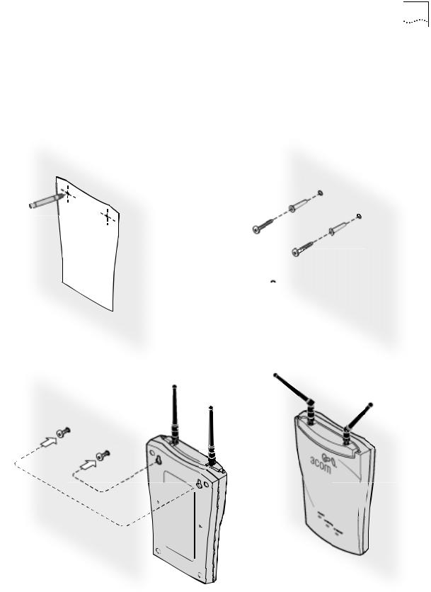
Mounting on a Wall To mount an access point on a wall, follow the instructions on the mounting template supplied in the box and refer to the following illustration. Preferably, mount the access point near the ceiling above any obstructions that could block transmission. Position the antenna so that the arms point out and away from the access point at a 45˚ angle
1 |
2 |
4

8 CHAPTER 2: INSTALLING THE ACCESS POINT
Mounting on a Ceiling To mount an access point to the T-rail grid of an acoustical ceiling, you must first attach the mounting bracket to the access point as shown.
ESET |
R |
|
|
|
|
PO |
T |
|
|
WO |
|
|
|
RE |
|
|
|
SU |
|
|
|
YL |
PP |
|
Align the T-rail grips with the ceiling T-rail, adjusting them so they grip the T-rail snugly. Tighten the screws on the T-rail grip. Position the antenna so that the arms point down and away from the access point at a 45˚ angle.
|
|
ER |
|
|
SET |
|
TO |
|
|
P |
|
|
WO |
|
SUP |
RE |
|
|
|
|
LYP |
|
|
|
E |
WIRE POWER |
|
LE |
|
|
THER |
SS |
|
NE |
|
|
T |
|
NOTE: After installation, there may be some play in the fit of the T-rail grips on the T-rail. This is likely due to the size of the T-rails but should not prevent a secure grip.
Connecting Power |
9 |
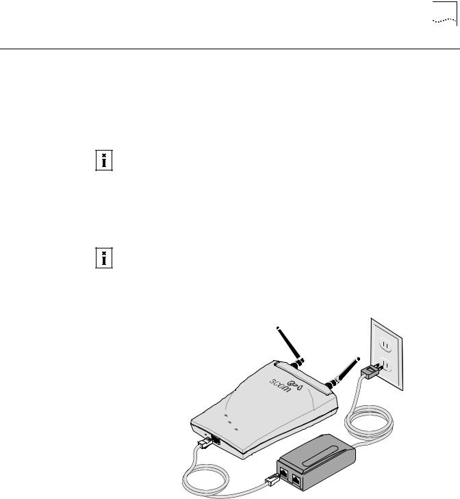
Connecting Power The access point is powered by the 3Com Integrated Power-over-Ethernet power supply, which provides power over a standard category 5 straight (8-wire) Ethernet cable. This eliminates the need to run standard power directly to the access point.
The power supply can be located at any point between the access point and the LAN access port (if you plan to connect to a wired LAN), wherever a convenient power outlet exists.LEDs light.
The access point is IEEE 802.3af compliant. Before connecting the access point to your own power-over-Ethernet hub or switch, ensure that your equipment also complies with the IEEE 802.3af standard.
When you connect the power make sure you connect the cable to the port labeled
To Access Point on the power supply. When the access point receives power, the
LEDs light.
If you supply your own Ethernet cable for connecting power, be sure that it is standard category 5 straight-through (8-wire) cable that has not been altered in any way. Use of nonstandard cable could damage the access point.
POWER
WIRELESS
ETHE
RNET
RESET
TO POW
ER SUPPLY
TO |
AC |
|
|
|
CE |
|
SS |
|
POI |
|
NT |
TO HUB/S
WITC
H
10 CHAPTER 2: INSTALLING THE ACCESS POINT
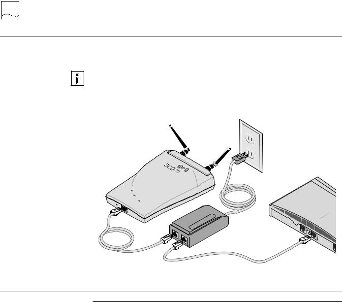
Connecting to an |
Use a standard Ethernet cable to connect the access point to an Ethernet network, |
Ethernet Network |
as shown below. |
To avoid damaging other components connected to the network, make sure that the Ethernet cable connected to the LAN port is plugged into the To Hub/Switch port on the power supply (not the To Access Point port).
POWER
WI
RELESS
ETHE
RNET
RESET
TO PO
WER SUPPLY
TO |
AC |
|
|
|
CE |
|
SS |
|
POI |
|
NT |
TO HUB/S
WITC
H
Checking the LEDs
LED |
Description |
|
|
Power |
■ On—Access point has power. |
|
■ Off—Access point is not receiving power. |
Wireless |
■ Blinking—The access point is operating. The blink speed ranges from |
|
approximately once every 2.5 seconds to approximately 10 times per |
|
second, depending on the signal strength and transmission speed. |
|
■ Off—The access point is not receiving power. |
Ethernet |
■ Blinking—Wired LAN traffic is detected. Faster blinking indicates |
|
heavier traffic. |
|
■ Off—There is no wired LAN connection or the access point is not |
|
receiving power. |
|
|
Selecting A Different Antenna 11
Selecting A Different The standard detachable portable antenna supplied with the access point is a Antenna multi-purpose antenna suitable for a variety of environments, including office
LANs, physical plants, and factory floors. If your site has special requirements that might be served by different types of antenna, four optional antenna models are available, as shown below:
Model number |
3CWE490 |
3CWE492 |
3CWE497 |
3CWE498 |
|
|||
|
|
|
|
|
||||
Design and type |
Omnidirectional |
Ceiling-mount |
Ceiling-mount |
Directional Panel |
||||
|
(fiberglass) |
omnidirectional |
hallway |
|
(indoor/outdoor) |
|||
|
|
|
|
|
||||
Frequency Range |
2.400-2.4835 GHz |
2300-2500 Mhz |
2300-2500 Mhz |
2300-2500 Mhz |
||||
|
|
|
|
|
|
|
|
|
Gain |
4 dBi |
|
2.5 dBi |
|
4 dBi |
|
8 dBi |
|
|
|
|
|
|
|
|
|
|
VSWR across band |
< 1.5:1 |
|
< 1.35:1 |
|
< 1.5:1 |
|
< 1.5:1 |
|
|
|
|
|
|
|
|
|
|
Distance (coverage)* |
2100 feet |
|
1800 feet |
|
2100 feet |
|
3600 feet |
|
|
|
|
|
|
|
|
|
|
Effective Radiated Power |
High: |
159 mW |
High: |
112 mW |
High: |
159 mW |
High: |
398 mW |
(ERP) @ different power |
Medium: |
50 mW |
Medium: |
36 mW |
Medium: |
50 mW |
Medium: |
126 mW |
transmission settings** |
Low: |
13 mW |
Low: |
9 mW |
Low: |
13 mW |
Low: |
32 mW |
|
|
|
|
|
||||
Temperature range |
-40° C to +80° C |
-40° C to +80° C |
-40° C to +71° C |
-40° C to +80° C |
||||
|
|
|
|
|
||||
Dimensions (inches) |
10” (height) |
4.25 (diameter) |
2.6 x 1.8 x 0.2 |
5.1 x 4.7 x 1.5 |
||||
|
|
|
|
|
|
|
|
|
Weight |
5.34 oz. |
|
8 oz. |
|
2 oz. |
|
8 oz. |
|
|
|
|||||||
Cable |
A six-foot accessory cable (model 3CWE480) is required for each of these optional antennas. It |
|||||||
|
provides the transition from the SMA connector on the access point to the N-type connector |
|||||||
|
on the antenna. A 20-foot cable (model 3CWE481) is also available. |
|
|
|||||
*Coverage varies depending on building construction.
**See “Setting Data Transmission Properties” on page 27 for information on selecting power transmission levels.
You can order any of the optional antennas by model number from the 3Com
Web site.
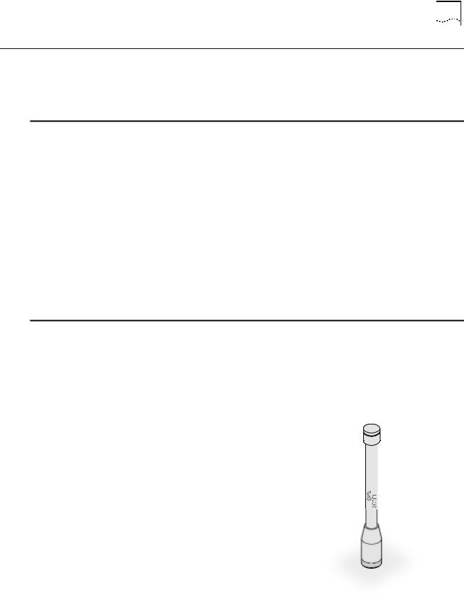
Omnidirectional Antenna
The fiberglass omnidirectional antenna (model number 3CWE490) is designed for use in harsh indoor environments. It can be centrally located on the ceiling to provide uniform coverage over a wide area.
This antenna features a built-in matching network that eliminates the need for a ground plane.
This antenna can be mounted on the ceiling by means of a standard ceiling-mount bracket. Before installing, ensure that access is available for cable routing.
This antenna does not have an electrical connection between the mask mount and the coaxial cable shield. However, adding a lightning arrestor will correct this situation by grounding the outer shield as recommended. Some arrestor designs provide over-voltage protection for the signal sent down the cable. If you use such

12 CHAPTER 2: INSTALLING THE ACCESS POINT
a design, be sure that it can pass signals used in the 2.5 GHz signal range. Many inexpensive units are available with F connectors, but these are typically designed for cable TV-UHF applications and may degrade the signals in the band used by the access point.
Ceiling Mount Omnidirectional Antenna
The ceiling-mount omnidirectional antenna (model number 3CWE492) is designed to cover large, open areas. It should be located at or near the center of the ceiling of a large, open area (such as an open office space divided into cubicles) to provide uniform coverage in all directions.
It is mounted by means of a single-hole stud mount, and so can be fixed easily to drop ceiling tiles or to a solid ceiling surface where cable routing access is available.
This antenna does not have an electrical connection between the mask mount and the coaxial cable shield. However, adding a lightning arrestor will correct this situation by grounding the outer shield as recommended. Some arrestor designs provide over-voltage protection for the signal sent down the cable. If you use such a design, be sure that it can pass signals used in the 2.5 GHz signal range. Many inexpensive units are available with F connectors, but these are typically designed for cable TV-UHF applications and may degrade the signals in the band used by the access point.
Ceiling Mount Hallway Antenna
The ceiling-mount hallway antenna (model number 3CWE497) has a bidirectional design that makes it ideal for use in long corridors. Its small size means it can provide extended WLAN coverage with minimum visibility.
This model includes a bracket for quick installation on standard one-inch ceiling rails. In addition, mounting holes allow for installation to any flat surface with screws.
 Loading...