


 Loading...
Wireless LAN Mobility System
Wireless LAN Switch and Controller
Hardware Installation Guide
WX4400 3CRWX440095A
WX2200 3CRWX220095A
WX1200 3CRWX120695A
WXR100 3CRWXR10095A
http://www.3Com.com/
Part No. 10015911 Rev AB
Published November 2007
3Com Corporation 350 Campus Drive Marlborough, MA USA 01752-3064
Copyright © 2007, 3Com Corporation. All rights reserved. No part of this documentation may be reproduced in any form or by any means or used to make any derivative work (such as translation, transformation, or adaptation) without written permission from 3Com Corporation.
3Com Corporation reserves the right to revise this documentation and to make changes in content from time to time without obligation on the part of 3Com Corporation to provide notification of such revision or change.
3Com Corporation provides this documentation without warranty, term, or condition of any kind, either implied or expressed, including, but not limited to, the implied warranties, terms or conditions of merchantability, satisfactory quality, and fitness for a particular purpose. 3Com may make improvements or changes in the product(s) and/or the program(s) described in this documentation at any time.
If there is any software on removable media described in this documentation, it is furnished under a license agreement included with the product as a separate document, in the hard copy documentation, or on the removable media in a directory file named LICENSE.TXT or !LICENSE.TXT. If you are unable to locate a copy, please contact 3Com and a copy will be provided to you.
UNITED STATES GOVERNMENT LEGEND
If you are a United States government agency, then this documentation and the software described herein are provided to you subject to the following:
All technical data and computer software are commercial in nature and developed solely at private expense. Software is delivered as “Commercial Computer Software” as defined in DFARS 252.227-7014 (June 1995) or as a “commercial item” as defined in FAR 2.101(a) and as such is provided with only such rights as are provided in 3Com’s standard commercial license for the Software. Technical data is provided with limited rights only as provided in DFAR 252.227-7015 (Nov 1995) or FAR 52.227-14 (June 1987), whichever is applicable. You agree not to remove or deface any portion of any legend provided on any licensed program or documentation contained in, or delivered to you in conjunction with, this User Guide.
Unless otherwise indicated, 3Com registered trademarks are registered in the United States and may or may not be registered in other countries.
3Com and the 3Com logo are registered trademarks of 3Com Corporation.
Mobility Domain, Mobility Point, Mobility Profile, Mobility System, Mobility System Software, MP, MSS, and SentrySweep are trademarks of Trapeze Networks, Inc.
Intel and Pentium are registered trademarks of Intel Corporation. Microsoft, MS-DOS, Windows, Windows XP, and Windows NT are registered trademarks of Microsoft Corporation.
All other company and product names may be trademarks of the respective companies with which they are associated.

CONTENTS
ABOUT THIS GUIDE
|
Conventions |
6 |
|
|
|
|
|
Documentation |
7 |
|
|
|
|
|
Documentation Comments |
8 |
|
|||
|
|
|
|
|||
1 WX SWITCH OVERVIEW |
|
|
||||
|
WX Model Numbers |
9 |
|
|
|
|
|
Hardware Features |
10 |
|
|
|
|
|
WX2200 Switch |
10 |
|
|
|
|
|
WXR100 Switch |
11 |
|
|
|
|
|
WX1200 Switch |
12 |
|
|
|
|
|
WX4400 Switch |
13 |
|
|
|
|
|
Management Features |
14 |
|
|||
|
Power Features |
14 |
|
|
|
|
|
Network Interfaces 15 |
|
|
|||
|
WX1200, WX4400, and WX2200 Status LEDs |
16 |
||||
|
WXR100 LEDs |
17 |
|
|
|
|
|
Software Features |
19 |
|
|
|
|
|
Management Features |
19 |
|
|||
|
Layer 2 Switching Features |
19 |
|
|||
|
IP Services |
20 |
|
|
|
|
|
Authentication, Authorization, and Accounting |
20 |
||||
|
Roaming |
20 |
|
|
|
|
|
RF Management |
21 |
|
|
|
|
|
|
|||||
2 INSTALLING AND CONNECTING A WX SWITCH |
||||||
|
Unpacking a WX Switch |
23 |
|
|
||
|
Installation Requirements and Recommendations |
25 |
||||
|
3Com Wireless Switch Manager Network Plan |
25 |
||||
|
Installation Location |
25 |
|
|
||
|
Cable Requirements |
26 |
|
|
||

Installation Hardware and Tools |
29 |
|
||
Installing a WX Switch |
30 |
|
|
|
Equipment Rack Installation 31 |
|
|||
Tabletop Installation |
33 |
|
|
|
Installing a Power Supply in a WX4400 Switch |
34 |
|||
Installing a New Power Supply |
34 |
|
||
Replacing a Power Supply |
35 |
|
|
|
Powering On a WX Switch |
37 |
|
|
|
Powering On a WXR100 Switch |
37 |
|
||
Connecting to a Serial Management Console |
38 |
|||
Troubleshooting a Serial Management Connection 39 |
||||
Connecting to the Network |
39 |
|
|
|
Connecting to a MAP or Other 10/100 Ethernet Device 39 |
||||
Connecting to Gigabit Ethernet Devices |
42 |
|||
AWX TECHNICAL SPECIFICATIONS
BWX TROUBLESHOOTING
COBTAINING SUPPORT FOR YOUR 3COM PRODUCTS
Register Your Product to Gain Service Benefits 57 Solve Problems Online 57
Purchase Extended Warranty and Professional Services 58 Access Software Downloads 58
Contact Us 58
Telephone Technical Support and Repair 59
INDEX

ABOUT THIS GUIDE
This guide shows you how to install a 3Com Wireless LAN Switch (WX) in a 3Com Mobility System wireless LAN (WLAN) and deploy basic IEEE 802.11 wireless service.
Read this guide if you are a network administrator or other person installing WX switches and deploying 802.11 wireless service in a network.
The 3Com Mobility System is an enterprise-class WLAN solution that seamlessly integrates with an existing wired enterprise network. The 3Com system provides secure connectivity to both wireless and wired users in large environments such as office buildings, hospitals, and university campuses and in small environments such as branch offices.
The 3Com Mobility System fulfills the three fundamental requirements of an enterprise WLAN: It eliminates the distinction between wired and wireless networks, allows users to work safely from anywhere (secure mobility), and provides a comprehensive suite of intuitive tools for planning and managing the network before and after deployment, greatly easing the operational burden on IT resources.
If release notes are shipped with your product and the information there differs from the information in this guide, follow the instructions in the release notes.
Most user guides and release notes are available in Adobe Acrobat Reader Portable Document Format (PDF) or HTML on the 3Com World Wide Web site:
http://www.3com.com/

6 ABOUT THIS GUIDE
Conventions |
Table 1 and Table 2 list conventions that are used throughout this guide. |
||||
|
Table 1 |
Notice Icons |
|
||
|
|
|
|
|
|
|
|
Icon |
Notice Type |
Description |
|
|
|
|
|
|
|
|
|
|
|
Information note |
Information that describes important features or |
|
|
|
|
|
instructions |
|
|
|
|
Caution |
Information that alerts you to potential loss of data or |
|
|
|
|
|
potential damage to an application, system, or device |
|
|
|
|
Warning |
Information that alerts you to potential equipment |
|
|
|
|
||
|
|
|
|
|
damage or personal injury. |
|
|
|
|
|
|
Table 2 Text Conventions
Convention |
Description |
|
|
Monospace text |
Sets off command syntax or sample commands and system |
|
responses. |
|
|
Bold text |
Highlights commands that you enter or items you select. |
|
|
Italic text |
Designates command variables that you replace with |
|
appropriate values, or highlights publication titles or words |
|
requiring special emphasis. |
|
|
[ ] (square brackets) |
Enclose optional parameters in command syntax. |
|
|
{ } (curly brackets) |
Enclose mandatory parameters in command syntax. |
|
|
| (vertical bar) |
Separates mutually exclusive options in command syntax. |
|
|
Keyboard key names |
If you must press two or more keys simultaneously, the key |
|
names are linked with a plus sign (+). Example: |
|
Press Ctrl+Alt+Del |
|
|
Words in italics |
Italics are used to: |
|
Emphasize a point. |
|
Denote a new term at the place where it is defined in the |
|
text. |
|
Highlight an example string, such as a username or SSID. |
|
|

Documentation 7
Documentation |
The MSS documentation set includes the following documents. |
Wireless Switch Manager (3WXM) Release Notes
These notes provide information about the 3WXM software release, including new features and bug fixes.
Wireless LAN Switch and Controller Release Notes
These notes provide information about the MSS software release, including new features and bug fixes.
Wireless LAN Switch and Controller Quick Start Guide
This guide provides instructions for performing basic setup of secure (802.1X) and guest (WebAAA™) access, and for configuring a Mobility Domain for roaming.
Wireless Switch Manager Reference Manual
This manual shows you how to plan, configure, deploy, and manage a Mobility System wireless LAN (WLAN) using the 3Com Wireless Switch Manager (3WXM).
Wireless Switch Manager User’s Guide
This guide shows you how to plan, configure, deploy, and manage a Mobility System wireless LAN (WLAN) using the 3Com Wireless Switch Manager (3WXM). It contains information about recommended system requirements you should meet for optimum 3WXM performance, installing 3WXM client and 3WXM Services software, and an introduction to using the 3WXM interface.
Wireless LAN Switch and Controller Hardware Installation Guide
This guide provides instructions and specifications for installing a WX wireless switch in a Mobility System WLAN.
Wireless LAN Switch and Controller Configuration Guide
This guide provides instructions for configuring and managing the system through the Mobility System Software (MSS) CLI.
Wireless LAN Switch and Controller Command Reference
This reference provides syntax information for all MSS commands supported on WX switches.

8 ABOUT THIS GUIDE
Documentation |
Your suggestions are very important to us. They will help make our |
Comments |
documentation more useful to you. Please e-mail comments about this |
|
document to 3Com at: |
|
pddtechpubs_comments@3com.com |
|
Please include the following information when contacting us: |
|
Document title |
|
Document part number and revision (on the title page) |
|
Page number (if appropriate) |
Example:
Wireless LAN Switch and Controller Configuration Guide
Part number 730-9502-0071, Revision B
Page 25
Please note that we can only respond to comments and questions about 3Com product documentation at this e-mail address. Questions related to Technical Support or sales should be directed in the first instance to your network supplier.

1 |
WX SWITCH OVERVIEW |
|
A 3Com Wireless Switch (WX) provides mobility and authentication, authorization, and accounting (AAA) services for wireless or wired users. A WX switch also controls the operation of 3Com Managed Access Point (MAP) access points, which control and manage IEEE 802.11 operation over the air.
WARNING: Installation must be performed by qualified service personnel only. Read and follow all warning notices and instructions marked on the product or included in the documentation.
WARNING: There are no user-serviceable parts inside the WX switches.
WX Model Numbers Table 3 lists the WX switch model numbers.
Table 3 WX Switch Model Numbers
Model |
Port Configuration |
Power Supply Configuration |
WX2200 |
Two gigabit Ethernet ports. Each |
Two 100-240V VAC autosensing |
|
port has a miniature Gigabit |
AC power supplies |
|
interface converter (mini-GBIC) slot |
|
|
for insertion of a small form-factor |
|
|
pluggable (SFP) 1000BASE-SX or |
|
|
1000BASE-LX fiber-optic interface. |
|
|
One 10/100 Ethernet port for out-of- |
|
|
band management (without PoE). |
|
|
|
|
WXR100 |
Two 10/100BASE-TX Ethernet ports |
One 100-240 VAC autosensing AC |
|
Port 1 provides an uplink to the |
power supply |
|
network. |
|
|
Port 2 supports Power over Ethernet (PoE) |
|
|
and provides direct connection to a MAP |
|
|
|
|
WX1200 |
Eight 10/100 Ethernet ports, six of |
One 100-120 VAC / 200-240 VAC |
|
which support PoE |
autosensing AC power supply |
|
|
|

10 CHAPTER 1: WX SWITCH OVERVIEW
Table 3 WX Switch Model Numbers (continued)
Model Port Configuration |
Power Supply Configuration |
WX4400 Four dual-interface gigabit Ethernet ports. Each port has a 1000BASE-TX copper interface and a Gigabit interface converter (GBIC) slot for insertion of a 1000BASE-SX or 1000BASE-LX fiber-optic interface.
Two 100-120 VAC / 200-240 VAC autosensing AC power supplies
Hardware Features The following sections describe the WX hardware features.
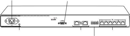
WX2200 Switch A WX2200 switch is one RU high and also can be installed in a standard 48.26-cm (19-inch) equipment rack or on a tabletop. Figure 1 shows the features of a WX2200 switch.
Figure 1 3Com WX2200 Switch
Power |
Serial |
|
console port |
||
supplies |
||
|
Provide an Earthing Connection |
|
|
90 - 240V~ / 50 - 60 Hz |
|
|
2.0 / 1.0A |
|
|
Mgmt (3) |
|
|
Console |
1 |
2 |
Power |
|
|
|
|
supply LEDs |
Mgmt |
10/100 |
Mini-GBIC |
Gigabit link |
|
||||
|
LED |
Management |
slots |
LEDs |
|
|
Port |
|
|
The rear of the switch contains a label with the serial ID, MAC address, and other identifying information.
Hardware Features |
11 |
WXR100 Switch A WXR100 switch is compact and can be installed on a tabletop. Figure 2 shows the external hardware features of an WXR100 switch.
Figure 2 3Com WXR100 Switch
CAUTION: Do not stack WXR100 switches. Stacked WXR100 switches can overheat and cause loss of equipment functionality or permanent damage.
CAUTION: Ensure adequate airflow around WXR100 switches. The WXR100 switch uses natural convection cooling and requires free entry of air. Airflow blockage can cause the system to overheat and result in a loss of equipment functionality or permanent damage.
The underside of the switch contains a label with the serial ID,
MAC address and other identifying information.
12 CHAPTER 1: WX SWITCH OVERVIEW
WX1200 Switch A WX1200 switch is one RU high and can be installed in a standard 48.26-cm (19-inch) equipment rack or on a tabletop. Figure 3 shows the external hardware features of a WX1200 switch.
Figure 3 3Com WX1200 Switch—Control Features
Power |
Serial |
supply |
console port |
Power |
10/100 Ethernet |
10/100 and MAP |
supply LED |
uplink ports |
Ethernet ports |
10/100 and MAP/PoE LEDs
The rear of the switch contains a label with the serial ID, MAC address, and other identifying information.

Hardware Features |
13 |
WX4400 Switch A WX4400 switch is two rack units (RUs) high and can be installed in a standard 48.26-cm (19-inch) equipment rack or on a tabletop. Figure 4 identifies the external hardware features of a WX4400 switch.
Figure 4 3Com WX4400 Switch—Control Features
Power |
Power |
Serial |
Flash |
Eject |
Mgmt |
supply LED |
supply |
console port |
card slot |
button |
LED |
100-240V |
Mgmt |
50/60 Hz |
Console |
8A MAX |
|
DISCONNECT |
|
ALL POWER |
|
BEFORE |
|
SERVICING |
|
AC power |
Power supply GBIC slot |
Gigabit |
1000BASE-TX port |
inlet |
serial number |
link |
|
|
|
LEDs |
|
Like the WX1200, the rear of the WX4400 contains a label with the serial ID, MAC address, and other identifying information.

14 CHAPTER 1: WX SWITCH OVERVIEW
Management |
Serial console port—The serial console port provides a direct |
Features |
management connection to a WX switch’s command-line interface |
|
(CLI). The port has a DB-9 female connector and supports the |
|
EIA-232D signaling standard. |
|
10/100 out-of-band management port—The WX2200 switch features |
|
an out-of-band management port, which allows you to connect the |
|
switch to a network server and configure the switch to boot using a |
|
software image downloaded from the server. The WXR100 also |
|
supports booting with a software image downloaded from a server. |
CAUTION: The Fn switch on the WXR100 performs two functions. If you press the Fn switch for less than 5 seconds, it restarts the WXR100 and reloads its configuration from the configuration file. However, if you press the switch for 5 seconds or longer, the configuration file is deleted and the switch restarts with its factory default settings. If you accidentally press the Fn switch for too long and erase the configuration, you can use the Web Quick Start to reconfigure the switch.
Status LEDs—The Ethernet ports and power supplies have LEDs that indicate their status. The management CPU on a WX4400 or WX2200 switch also has an LED. (For details, see “WX1200, WX4400, and WX2200 Status LEDs” on page 16.)
Flash card slot (WX4400 only)—The flash card slot is not used for normal WX operation.
Power Features Power supplies—A WX4400 switch comes with one 100-240 VAC autosensing AC power supply. You can add a second supply for load sharing and redundancy. The power supplies are hot-swappable.
A WX1200 switch contains one 100-120 VAC / 200-240 VAC autosensing AC power supply. The WX1200 power supply is a fixed-configuration supply and cannot be inserted or removed.
A WX2200 switch contains two 100-240V VAC autosensing AC power supplies.
A WXR100 switch uses an external power supply, which comes with the switch.
Hardware Features 15
Network Interfaces 10/100 Ethernet ports—A WXR100 switch has two 10/100BASE-TX Ethernet ports. A WX1200 switch has eight 10/100BASE-TX Ethernet ports. Each port has a standard RJ-45 connector and uses Category 5 (Cat 5) cable based on the EIA/TIA-586 standard.
On the WXR100, port 2 can be configured for MAP access points and can support Power over Ethernet (PoE). Port 1 is an uplink port only and does not support PoE.
On the WX1200, ports 1 through 6 can be configured for MAP access points and can support PoE. Ports 7 and 8 on the WX1200 switch are uplink ports only and do not support PoE.
The 10/100 Ethernet ports on the WX1200, WX2200, and WXR100 switches provide automatic MDI/MDX, which automatically crosses over the send and receive signals if required.
The WX4400 and WX2200 switches provide high-bandwidth centralized control of many indirectly connected MAP access points. The WX4400 switch does not have 10/100 Ethernet ports and does not provide PoE. The WX2200 has one 10/100 Ethernet port (port 3); this port does not provide PoE.
Gigabit interface converter (GBIC) slots (WX4400 only)—A WX4400 switch has four ports. Each port has a slot for a 1000BASE-SX or 1000BASE-LX fiber-optic GBIC, and a built-in 1000BASE-TX copper interface with an RJ-45 connector. Only one interface, copper or fiber, can be active on a port. The GBIC interface is active by default.
Miniature Gigabit interface converter (mini-GBIC) slots (WX2200 only)—A WX2200 switch has two slots allowing insertion of small form-factor pluggable (SFP) 1000Base-SX, 1000Base-LX, 1000Base-T, or 1000Base-LH fiber-optic mini-GBICs to provide gigabit Ethernet interfaces to the network.
The mini-GBICs have standard SC Duplex connectors and use either single-mode fiber (SMF) for LX or multimode fiber (MMF) for SX. Mini-GBICs are available separately and are not included with the switch.
The gigabit Ethernet ports operate at 1000 Mbps only. They do not change speed to match 10-Mbps or 100-Mbps links.

16 CHAPTER 1: WX SWITCH OVERVIEW
WX1200, WX4400, The WX1200, WX4400, and WX2200 switches have LEDs that indicate and WX2200 Status port, power, and CPU status. Table 4 lists the LEDs. (For the location of
LEDs each LED, see Figure 3 and Figure 4.)
Table 4 WX1200, WX4400, and WX2200 Status LEDs
LED |
Appearance |
Meaning |
|
Mgmt |
Bright green, then |
WX switch is operating normally. |
|
(WX4400 and |
fade (repeated) |
|
|
|
|
||
WX2200 only) |
This LED appearance |
|
|
|
is sometimes called |
|
|
|
breathing. |
|
|
|
|
|
|
|
Blinking green |
WX switch is booting. |
|
|
|
|
|
|
Quickly blinking |
WX switch was unable to boot completely. |
|
|
amber |
|
|
|
|
|
|
Power supply |
Solid green |
DC power output is on. |
|
status |
|
|
|
Solid amber |
Power fault has occurred. |
||
|
|||
|
|
|
|
|
Unlit |
AC power is off. |
|
|
|
|
|
Gigabit fiber |
Solid green |
1000-Mbps fiber link is operational. |
|
link activity |
|
|
|
Blinking green |
Traffic is active on the 1000-Mbps fiber |
||
|
|||
(WX4400 and |
|
link. |
|
WX2200 only) |
|
|
|
|
|
|
|
Gigabit copper |
Solid green |
1000-Mbps copper link is operational. |
|
link activity |
|
|
|
Blinking green |
Traffic is active on the 1000-Mbps copper |
||
|
|||
(WX4400 and |
|
link. |
|
WX2200 only) |
|
|
|
|
|
|
|
Link |
Solid green |
100-Mbps link is operational. |
|
|
|
|
|
(WX1200 only) |
Solid amber |
10-Mbps link is operational. |
|
|
|
|
|
|
Blinking green |
Traffic is active on the 100-Mbps link. |
|
|
|
|
|
|
Blinking amber |
Traffic is active on the 10-Mbps link. |
|
|
|
|

|
|
Hardware Features 17 |
Table 4 WX1200, WX4400, and WX2200 Status LEDs (continued) |
||
|
|
|
LED |
Appearance |
Meaning |
|
|
|
MAP |
Solid green |
For a MAP access point’s active link, with |
(WX1200 only) |
|
PoE enabled, all the following are true: |
|
MAP access point has booted. |
|
|
|
|
|
|
MAP access point has received a valid |
|
|
configuration from the WX switch. |
|
|
Management link with a MAP access |
|
|
point is operational. |
|
|
|
|
Alternating green |
MAP access point is booting with an image |
|
and amber |
received from the WX switch. |
|
|
If the LED remains in this state indefinitely, |
|
|
the boot or configuration attempt has |
|
|
failed. |
|
|
|
|
Solid amber |
PoE is on but no MAP access point is |
|
|
connected to the link. |
|
|
|
|
Blinking amber |
MAP is not connected or is unresponsive, |
|
|
or there is a PoE problem. |
|
|
|
|
Unlit |
Port is not configured as a MAP access |
|
|
port, or PoE is off. |
|
|
|
WXR100 LEDs Figure 5 shows the locations of the WXR100 LEDs. Table 5 describes the LEDs.
Figure 5 WXR100 LEDs
FN LED |
MAP LED |
1 2
|
Power |
Link LED |
supply LED |

18 CHAPTER 1: WX SWITCH OVERVIEW
Table 5 WXR100 Status LEDs
LED |
Appearance |
Meaning |
|
|
|
Power status |
Solid green |
The switch is receiving power. |
|
|
|
|
Unlit |
The switch is not receiving power. |
|
|
|
Link |
Solid green |
100-Mbps link is operational. |
|
|
|
(ports 1 and 2) |
Solid amber |
10-Mbps link is operational. |
|
|
|
|
Blinking green |
Traffic is active on the 100-Mbps link. |
|
|
|
|
Blinking amber |
Traffic is active on the 10-Mbps link. |
|
|
|
Fn |
Solid green |
The switch is booting and is loading its |
(port 1 only) |
|
configuration file. This LED state lasts |
|
for three seconds. |
|
|
|
|
|
|
|
|
Blinking green |
The switch is booting but the Fn |
|
|
switch is being pressed. The switch |
|
|
does not load its configuration file but |
|
|
instead contacts WX to request a |
|
|
configuration. |
|
|
This LED state lasts for three seconds. |
|
|
|
|
Unlit |
The switch has finished booting. |
|
|
|
MAP (port 2 only) |
Solid green |
For a MAP access point’s active link, |
|
|
with PoE enabled, all the following are |
|
|
true: |
|
|
MAP access point has booted. |
|
|
MAP access point has received a valid |
|
|
configuration from the WX switch. |
|
|
Management link with an MAP access |
|
|
point is operational. |
|
|
|
|
Alternating green and |
MAP access point is booting with an |
|
amber |
image received from the WX switch. |
|
|
If the LED remains in this state |
|
|
indefinitely, the boot or configuration |
|
|
attempt has failed. |
|
|
|
|
Solid amber |
PoE is on but no MAP access point is |
|
|
connected to the link. |
|
|
|
|
Blinking amber |
MAP is not connected or is |
|
|
unresponsive, or there is a PoE |
|
|
problem. |
|
|
|
|
Unlit |
Port is not configured as a MAP access |
|
|
port, or PoE is off. |
|
|
|

Software Features |
19 |
Software Features |
Mobility System Software (MSS) provides a combination of standard |
|
wired LAN features and wireless LAN features that enable you to |
|
integrate the switch into your wired network and provide network access |
|
for wired or wireless users. |
Management |
Serial and network command-line interface (CLI) access—You can |
Features |
access the CLI through a direct serial connection or through the |
|
network using Secure Shell (SSH) or Telnet. |
|
3Com Wireless Switch Manager management application—3Com |
|
Wireless Switch Manager is an extensive GUI application for planning, |
|
configuring, deploying, and managing a 3Com network and its users. |
|
3Com Wireless Switch Manager uses Secure Sockets Layer protocol |
|
(SSL) to interact with MSS. |
|
Software and configuration management—You can store multiple |
|
software images and configuration files in the WX switch’s nonvolatile |
|
storage. |
|
Web View—Web View is a Web-based application for configuring and |
|
managing a single WX switch through a Web browser. Web View |
|
creates a secure connection by using Hypertext Transfer Protocol over |
|
Secure Sockets Layer (HTTPS). |
Layer 2 Switching |
Spanning Tree Protocol (STP)—MSS is 802.1D-compatible and |
Features |
supports Per-VLAN Spanning Tree (PVST+). PVST+ allows a separate |
|
spanning tree in each virtual LAN (VLAN). Optional fast convergence |
|
features allow you to quickly resume traffic forwarding after a |
|
topology change. |
|
Load-sharing port groups—You can configure multiple physical ports |
|
into a single logical link for traffic load sharing and physical link |
|
redundancy. |
|
Virtual LANs (VLANs)—MSS supports logical segmentation of a |
|
switch’s ports into separate Layer 2 collision domains. A port can be a |
|
member of one or more VLANs. Each VLAN can have its own IP |
|
interface. MSS supports the 802.1Q tag format. |
|
Internet Group Management Protocol (IGMP) snooping for multicast |
|
containment—The WX switch can learn about the multicast sources |
|
and receivers in the network and restrict forwarding for a multicast |
|
group to the users for that group. IGMPv1 and IGMPv2 are supported. |
20 CHAPTER 1: WX SWITCH OVERVIEW
IP Services |
IP interfaces—You can configure an IP interface for each VLAN. |
|
IP ping and traceroute—You can test IP connectivity between the WX |
|
switch and other devices. |
|
Domain Name Service (DNS)—You can configure the switch to use |
|
DNS servers for name resolution. You also can configure a default |
|
domain name to append to hostnames. |
|
Network Time Protocol (NTP)—A WX switch can sets its time and date |
|
by polling an NTP server. |
|
System log—A WX generates log messages to log system events. The log |
|
messages are stored locally and also can be exported to syslog servers. |
|
Simple Network Management Protocol (SNMP)—A WX switch can be |
|
configured to generate SNMP traps for major system events. |
Authentication, |
802.1X—A WX switch can authenticate users based on 802.1X |
Authorization, and |
protocols. Based on authentication, users are assigned VLAN |
Accounting |
membership, access control, and roaming boundaries. |
|
MAC authentication—If a device does not support 802.1X, you can |
|
configure authentication based on the source MAC address to assign |
|
VLAN membership, access control, and roaming boundaries. |
|
Guest authentication—Guests can be authenticated by a shared set of |
|
authorization attributes that assign VLAN membership, access control, |
|
and roaming boundaries. |
|
Local and remote authentication—You can authenticate users locally using |
|
information configured on the WX switch, or use a Remote Authentication |
|
Dial-In User Service (RADIUS) server. When you use a remote server, the WX |
|
switch can enhance performance by performing some of the AAA tasks |
|
locally or distributing the load across multiple servers. |
Roaming MAP access point roaming—You can configure the WX switch to allow users to roam from one MAP access point to another on the same WX switch.
Mobility Domain™ roaming—You also can configure a group of WX switches to allow users to roam from one switch to another. Regardless of the wired subnet connections, each user maintains the same IP address and session across the network.
Session management—You can display session information and statistics for users.
Loading...