


 Loading...
WA6102X-2
2.4 GHz / 5 GHz User Guide
Wireless Access Point
www.edge-core.com

User Guide
2.4 GHz / 5 GHz Wireless Access Point
IEEE 802.11g and 802.11a Dual-band Access Point with 1 10/100BASE-TX (RJ-45) Port
WA6102X-2AG-17 F4.3.2.0 E012006-R01 149100033300E
COMPLIANCES
Federal Communication Commission Interference
Statement
This equipment has been tested and found to comply with the limits for a Class B digital device, pursuant to Part 15 of the FCC Rules. These limits are designed to provide reasonable protection against harmful interference in a residential installation. This equipment generates, uses and can radiate radio frequency energy and, if not installed and used in accordance with the instructions, may cause harmful interference to radio communications. However, there is no guarantee that interference will not occur in a particular installation. If this equipment does cause harmful interference to radio or television reception, which can be determined by turning the equipment off and on, the user is encouraged to try to correct the interference by one of the following measures:
•Reorient or relocate the receiving antenna
•Increase the separation between the equipment and receiver
•Connect the equipment into an outlet on a circuit different from that to which the receiver is connected
•Consult the dealer or an experienced radio/TV technician for help
FCC Caution: Any changes or modifications not expressly approved by the party responsible for compliance could void the user's authority to operate this equipment. This device complies with Part 15 of the FCC Rules. Operation is subject to the following two conditions: (1) This device may not cause harmful interference, and (2) this device must accept any interference received, including interference that may cause undesired operation.
IMPORTANT NOTE:
FCC Radiation Exposure Statement
This equipment complies with FCC radiation exposure limits set forth for an uncontrolled environment. This equipment should be installed and operated with a minimum distance of 20 centimeters (8 inches) between the radiator and your body. This transmitter must not be co-located or operating in conjunction with any other antenna or transmitter.
Wireless 5 GHz Band Statements:
As the Access Point can operate in the 5150-5250 MHz frequency band it is limited by the FCC, Industry Canada and some other countries to indoor use only so as to reduce the potential for harmful interference to co-channel Mobile Satellite systems.
i

COMPLIANCES
High power radars are allocated as primary users (meaning they have priority) of the 5250-5350 MHz and 5650-5850 MHz bands. These radars could cause interference and /or damage to the access point when used in Canada.
The term “IC” before the radio certification number only signifies that Industry Canada technical specifications were met.
Industry Canada - Class B
This digital apparatus does not exceed the Class B limits for radio noise emissions from digital apparatus as set out in the interference-causing equipment standard entitled “Digital Apparatus,” ICES-003 of Industry Canada.
Cet appareil numérique respecte les limites de bruits radioélectriques applicables aux appareils numériques de Classe B prescrites dans la norme sur le matérial brouilleur: “Appareils Numériques,” NMB-003 édictée par l’Industrie.
Japan VCCI Class B
Australia/New Zealand AS/NZS 4771
ACN 066 352010
ii

COMPLIANCES
EC Conformance Declaration
Marking by the above symbol indicates compliance with the Essential Requirements of the R&TTE Directive of the European Union (1999/5/ EC). This equipment meets the following conformance standards:
•EN 60950-1 (IEC 60950-1) - Product Safety
•EN 301 893 - Technical requirements for 5 GHz radio equipment
•EN 300 328 - Technical requirements for 2.4 GHz radio equipment
•EN 301 489-1 / EN 301 489-17 - EMC requirements for radio equipment
Countries of Operation & Conditions of Use in the European
Community
This device is intended to be operated in all countries of the European Community. Requirements for indoor vs. outdoor operation, license requirements and allowed channels of operation apply in some countries as described below:
Note: The user must use the configuration utility provided with this product to ensure the channels of operation are in conformance with the spectrum usage rules for European Community countries as described below.
•This device requires that the user or installer properly enter the current country of operation in the command line interface as described in the user guide, before operating this device.
•This device will automatically limit the allowable channels determined by the current country of operation. Incorrectly entering the country of operation may result in illegal operation and may cause harmful interference to other systems. The user is obligated to ensure the device is operating according to the channel limitations, indoor/outdoor restrictions and license requirements for each European Community country as described in this document.
•This device employs a radar detection feature required for European Community operation in the 5 GHz band. This feature is automatically enabled when the country of operation is correctly configured for any European Community country. The presence of nearby radar operation may result in temporary interruption of operation of this device. The radar detection feature will automatically restart operation on a channel free of radar.
iii
COMPLIANCES
•The 5 GHz Turbo Mode feature is not allowed for operation in any European Community country. The current setting for this feature is found in the 5 GHz 802.11a Radio Settings Window as described in the user guide.
•The 5 GHz radio's Auto Channel Select setting described in the user guide must always remain enabled to ensure that automatic 5 GHz channel selection complies with European requirements. The current setting for this feature is found in the 5 GHz 802.11a Radio Settings Window as described in the user guide.
•This device is restricted to indoor use when operated in the European Community using the 5.15 - 5.35 GHz band: Channels 36, 40, 44, 48, 52, 56, 60, 64. See table below for allowed 5 GHz channels by country.
•This device may be operated indoors or outdoors in all countries of the European Community using the 2.4 GHz band: Channels 1 - 13, except where noted below.
-In Italy the end-user must apply for a license from the national spectrum authority to operate this device outdoors.
-In Belgium outdoor operation is only permitted using the 2.46 - 2.4835 GHz band: Channel 13.
-In France outdoor operation is only permitted using the 2.4 - 2.454 GHz band: Channels 1 - 7.
iv

COMPLIANCES
Operation Using 5 GHz Channels in the European
Community
The user/installer must use the provided configuration utility to check the current channel of operation and make necessary configuration changes to ensure operation occurs in conformance with European National spectrum usage laws as described below and elsewhere in this document.
Allowed 5GHz Channels in Each European Community Country
Allowed Frequency Bands |
Allowed Channel Numbers |
Countries |
|
|
|
5.15 - 5.25 GHz* |
36, 40, 44, 48 |
Austria, Belgium |
|
|
|
5.15 - 5.35 GHz* |
36, 40, 44, 48, 52, 56, 60, 64 |
France, |
|
|
Switzerland, |
|
|
Liechtenstein |
|
|
|
5.15 - 5.35* & 5.470 - 5.725 |
36, 40, 44, 48, 52, 56, 60, 64, |
Denmark, Finland, |
GHz |
100, 104, 108, 112, 116, 120, |
Germany, Iceland, |
|
124, 128, 132, 136, 140 |
Ireland, Italy, |
|
|
Luxembourg, |
|
|
Netherlands, |
|
|
Norway, Portugal, |
|
|
Spain, Sweden, |
|
|
U.K. |
|
|
|
5 GHz Operation Not |
None |
Greece |
Allowed |
|
|
|
|
|
*Outdoor operation is not allowed using 5.15-5.35 GHz bands (Channels 36 - 64).
v
COMPLIANCES
Declaration of Conformity in Languages of the European
Community
English |
Hereby, SMC, declares that this Radio LAN device is in |
|
compliance with the essential requirements and other relevant |
|
provisions of Directive 1999/5/EC. |
|
|
Finnish |
Valmistaja SMC vakuuttaa täten että Radio LAN device tyyppinen |
|
laite on direktiivin 1999/5/EY oleellisten vaatimusten ja sitä |
|
koskevien direktiivin muiden ehtojen mukainen. |
|
|
Dutch |
Hierbij verklaart SMC dat het toestel Radio LAN device in |
|
overeenstemming is met de essentiële eisen en de andere |
|
relevante bepalingen van richtlijn 1999/5/EG |
|
Bij deze SMC dat deze Radio LAN device voldoet aan de |
|
essentiële eisen en aan de overige relevante bepalingen van |
|
Richtlijn 1999/5/EC. |
|
|
French |
Par la présente SMC déclare que l'appareil Radio LAN device est |
|
conforme aux exigences essentielles et aux autres dispositions |
|
pertinentes de la directive 1999/5/CE |
|
|
Swedish |
Härmed intygar SMC att denna Radio LAN device står I |
|
överensstämmelse med de väsentliga egenskapskrav och övriga |
|
relevanta bestämmelser som framgår av direktiv 1999/5/EG. |
|
|
Danish |
Undertegnede SMC erklærer herved, at følgende udstyr Radio |
|
LAN device overholder de væsentlige krav og øvrige relevante |
|
krav i direktiv 1999/5/EF |
|
|
German |
Hiermit erklärt SMC, dass sich dieser/diese/dieses Radio LAN |
|
device in Übereinstimmung mit den grundlegenden |
|
Anforderungen und den anderen relevanten Vorschriften der |
|
Richtlinie 1999/5/EG befindet". (BMWi) |
|
Hiermit erklärt SMC die Übereinstimmung des Gerätes Radio |
|
LAN device mit den grundlegenden Anforderungen und den |
|
anderen relevanten Festlegungen der Richtlinie 1999/5/EG. |
|
(Wien) |
|
|
Greek |
με την παρουσα SMC δηλωνει οτι radio LAN device |
|
συμμορφωνεται προσ τισ ουσιωδεισ απαιτησεισ και τισ λοιπεσ |
|
σΧετικεσ διαταξεισ τησ οδηγιασ 1999/5/εκ |
|
|
Italian |
Con la presente SMC dichiara che questo Radio LAN device è |
|
conforme ai requisiti essenziali ed alle altre disposizioni pertinenti |
|
stabilite dalla direttiva 1999/5/CE. |
|
|
vi
|
COMPLIANCES |
|
|
Spanish |
Por medio de la presente Manufacturer declara que el Radio LAN |
|
device cumple con los requisitos esenciales y cualesquiera otras |
|
disposiciones aplicables o exigibles de la Directiva 1999/5/CE |
|
|
Portuguese |
Manufacturer declara que este Radio LAN device está conforme |
|
com os requisitos essenciais e outras disposições da Directiva |
|
1999/5/CE. |
|
|
Safety Compliance
Power Cord Safety
Please read the following safety information carefully before installing the access point:
WARNING: Installation and removal of the unit must be carried out by qualified personnel only.
•The unit must be connected to an earthed (grounded) outlet to comply with international safety standards.
•Do not connect the unit to an A.C. outlet (power supply) without an earth (ground) connection.
•The appliance coupler (the connector to the unit and not the wall plug) must have a configuration for mating with an EN 60320/IEC 320 appliance inlet.
•The socket outlet must be near to the unit and easily accessible. You can only remove power from the unit by disconnecting the power cord from the outlet.
•This unit operates under SELV (Safety Extra Low Voltage) conditions according to IEC 60950. The conditions are only maintained if the equipment to which it is connected also operates under SELV conditions.
France and Peru only
This unit cannot be powered from IT† supplies. If your supplies are of IT type, this unit must be powered by 230 V (2P+T) via an isolation transformer ratio 1:1, with the secondary connection point labelled Neutral, connected directly to earth (ground).
† Impédance à la terre
vii

COMPLIANCES
Important! Before making connections, make sure you have the correct cord set. Check it (read the label on the cable) against the following:
Power Cord Set
U.S.A. and |
The cord set must be UL-approved and CSA certified. |
|
Canada |
|
|
The minimum specifications for the flexible cord are: |
||
|
||
|
- No. 18 AWG - not longer than 2 meters, or 16 AWG. |
|
|
- Type SV or SJ |
|
|
- 3-conductor |
|
|
|
|
|
The cord set must have a rated current capacity of at least |
|
|
10 A |
|
|
|
|
|
The attachment plug must be an earth-grounding type with |
|
|
NEMA 5-15P (15 A, 125 V) or NEMA 6-15P (15 A, 250 V) |
|
|
configuration. |
|
|
|
|
Denmark |
The supply plug must comply with Section 107-2-D1, |
|
|
Standard DK2-1a or DK2-5a. |
|
|
|
|
Switzerland |
The supply plug must comply with SEV/ASE 1011. |
|
|
|
|
U.K. |
The supply plug must comply with BS1363 (3-pin 13 A) and |
|
|
be fitted with a 5 A fuse which complies with BS1362. |
|
|
|
|
|
The mains cord must be <HAR> or <BASEC> marked and |
|
|
be of type HO3VVF3GO.75 (minimum). |
|
|
|
|
Europe |
The supply plug must comply with CEE7/7 (“SCHUKO”). |
|
|
|
|
|
The mains cord must be <HAR> or <BASEC> marked and |
|
|
be of type HO3VVF3GO.75 (minimum). |
|
|
|
|
|
IEC-320 receptacle. |
|
|
|
viii

COMPLIANCES
Veuillez lire à fond l'information de la sécurité suivante avant d'installer le access point:
AVERTISSEMENT: L’installation et la dépose de ce groupe doivent être confiés à un personnel qualifié.
•Ne branchez pas votre appareil sur une prise secteur (alimentation électrique) lorsqu'il n'y a pas de connexion de mise à la terre (mise à la masse).
•Vous devez raccorder ce groupe à une sortie mise à la terre (mise à la masse) afin de respecter les normes internationales de sécurité.
•Le coupleur d’appareil (le connecteur du groupe et non pas la prise murale) doit respecter une configuration qui permet un branchement sur une entrée d’appareil EN 60320/IEC 320.
•La prise secteur doit se trouver à proximité de l’appareil et son accès doit être facile. Vous ne pouvez mettre l’appareil hors circuit qu’en débranchant son cordon électrique au niveau de cette prise.
•L’appareil fonctionne à une tension extrêmement basse de sécurité qui est conforme à la norme IEC 60950. Ces conditions ne sont maintenues que si l’équipement auquel il est raccordé fonctionne dans les mêmes conditions.
France et Pérou uniquement:
Ce groupe ne peut pas être alimenté par un dispositif à impédance à la terre. Si vos alimentations sont du type impédance à la terre, ce groupe doit être alimenté par une tension de 230 V (2 P+T) par le biais d’un transformateur d’isolement à rapport 1:1, avec un point secondaire de connexion portant l’appellation Neutre et avec raccordement direct à la terre (masse).
Cordon électrique - Il doit être agréé dans le pays d’utilisation
Etats-Unis et |
Le cordon doit avoir reçu l’homologation des UL et un |
Canada: |
certificat de la CSA. |
|
|
|
Les spécifications minimales pour un cable flexible sont |
|
AWG No. 18, ou AWG No. 16 pour un cable de longueur |
|
inférieure à 2 mètres. |
|
- type SV ou SJ |
|
- 3 conducteurs |
|
|
|
Le cordon doit être en mesure d’acheminer un courant |
|
nominal d’au moins 10 A. |
|
|
|
La prise femelle de branchement doit être du type à mise à |
|
la terre (mise à la masse) et respecter la configuration NEMA |
|
5-15P (15 A, 125 V) ou NEMA 6-15P (15 A, 250 V). |
|
|
Danemark: |
La prise mâle d’alimentation doit respecter la section 107-2 |
|
D1 de la norme DK2 1a ou DK2 5a. |
|
|
ix

COMPLIANCES
Cordon électrique - Il doit être agréé dans le pays d’utilisation
Suisse: |
La prise mâle d’alimentation doit respecter la norme SEV/ |
|
ASE 1011. |
|
|
Europe |
La prise secteur doit être conforme aux normes CEE 7/7 |
|
(“SCHUKO”) |
|
LE cordon secteur doit porter la mention <HAR> ou |
|
<BASEC> et doit être de type HO3VVF3GO.75 (minimum). |
|
|
Bitte unbedingt vor dem Einbauen des Access Point die folgenden Sicherheitsanweisungen durchlesen (Germany):
WARNUNG: Die Installation und der Ausbau des Geräts darf nur durch Fachpersonal erfolgen.
•Das Gerät sollte nicht an eine ungeerdete Wechselstromsteckdose angeschlossen werden.
•Das Gerät muß an eine geerdete Steckdose angeschlossen werden, welche die internationalen Sicherheitsnormen erfüllt.
•Der Gerätestecker (der Anschluß an das Gerät, nicht der Wandsteckdosenstecker) muß einen gemäß EN 60320/IEC 320 konfigurierten Geräteeingang haben.
•Die Netzsteckdose muß in der Nähe des Geräts und leicht zugänglich sein. Die Stromversorgung des Geräts kann nur durch Herausziehen des Gerätenetzkabels aus der Netzsteckdose unterbrochen werden.
•Der Betrieb dieses Geräts erfolgt unter den SELV-Bedingungen (Sicherheitskleinstspannung) gemäß IEC 60950. Diese Bedingungen sind nur gegeben, wenn auch die an das Gerät angeschlossenen Geräte unter SELV-Bedingungen betrieben werden.
•
x

COMPLIANCES
Stromkabel. Dies muss von dem Land, in dem es benutzt wird geprüft werden:
U.S.A und |
Der Cord muß das UL gepruft und war das CSA |
Kanada |
beglaubigt. |
|
|
|
Das Minimum spezifikation fur der Cord sind: |
|
- Nu. 18 AWG - nicht mehr als 2 meter, oder 16 AWG. |
|
- Der typ SV oder SJ |
|
- 3-Leiter |
|
|
|
Der Cord muß haben eine strombelastbarkeit aus |
|
wenigstens 10 A |
|
|
|
Dieser Stromstecker muß hat einer erdschluss mit der typ |
|
NEMA 5-15P (15A, 125V) oder NEMA 6-15P (15A, 250V) |
|
konfiguration. |
|
|
Danemark |
Dieser Stromstecker muß die ebene 107-2-D1, der |
|
standard DK2-1a oder DK2-5a Bestimmungen einhalten. |
|
|
Schweiz |
Dieser Stromstecker muß die SEV/ASE |
|
1011Bestimmungen einhalten. |
|
|
Europe |
Das Netzkabel muß vom Typ HO3VVF3GO.75 |
|
(Mindestanforderung) sein und die Aufschrift <HAR> oder |
|
<BASEC> tragen. |
|
Der Netzstecker muß die Norm CEE 7/7 erfüllen |
|
(”SCHUKO”). |
|
|
xi
COMPLIANCES
xii

Table of Contents
Chapter 1: Introduction |
1-1 |
Package Checklist |
1-2 |
Hardware Description |
1-2 |
Component Description |
1-3 |
Features and Benefits |
1-5 |
Applications |
1-6 |
System Defaults |
1-6 |
|
|
Chapter 2: Hardware Installation |
2-1 |
|
|
Chapter 3: External Antennas |
3-1 |
Instalation Procedures |
3-1 |
|
|
Chapter 4: Network Configuration |
4-1 |
Network Topologies |
4-2 |
Ad Hoc Wireless LAN (no Access Point) |
4-2 |
Infrastructure Wireless LAN |
4-3 |
Infrastructure Wireless LAN for Roaming Wireless PCs |
4-4 |
Infrastructure Wireless Bridge |
4-5 |
Infrastructure Wireless Repeater |
4-6 |
|
|
Chapter 5: Initial Configuration |
5-1 |
Initial Setup through the CLI |
5-1 |
Required Connections |
5-1 |
Initial Configuration Steps |
5-2 |
Logging In |
5-3 |
|
|
Chapter 6: System Configuration |
6-1 |
Advanced Configuration |
6-2 |
System Identification |
6-3 |
TCP / IP Settings |
6-5 |
RADIUS |
6-7 |
SSH Settings |
6-11 |
Authentication |
6-12 |
xiii

Contents
Filter Control |
6-17 |
VLAN |
6-19 |
WDS Settings |
6-21 |
AP Management |
6-27 |
Administration |
6-28 |
System Log |
6-33 |
RSSI |
6-37 |
SNMP |
6-37 |
Configuring SNMP and Trap Message Parameters |
6-38 |
Configuring SNMPv3 Users |
6-42 |
Configuring SNMPv3 Trap Filters |
6-44 |
Configuring SNMPv3 Targets |
6-46 |
Radio Interface |
6-48 |
Radio Settings A (802.11a) |
6-49 |
Radio Settings G (802.11g) |
6-63 |
Security |
6-66 |
Status Information |
6-84 |
Access Point Status |
6-84 |
Station Status |
6-87 |
Event Logs |
6-90 |
|
|
Chapter 7: Command Line Interface |
7-1 |
Using the Command Line Interface |
7-1 |
Accessing the CLI |
7-1 |
Console Connection |
7-1 |
Telnet Connection |
7-1 |
Entering Commands |
7-2 |
Keywords and Arguments |
7-2 |
Minimum Abbreviation |
7-2 |
Command Completion |
7-3 |
Getting Help on Commands |
7-3 |
Partial Keyword Lookup |
7-4 |
Negating the Effect of Commands |
7-4 |
Using Command History |
7-4 |
Understanding Command Modes |
7-4 |
Exec Commands |
7-5 |
Configuration Commands |
7-5 |
Command Line Processing |
7-6 |
Command Groups |
7-6 |
General Commands |
7-7 |
configure |
7-8 |
end |
7-8 |
exit |
7-8 |
ping |
7-9 |
xiv

Contents
reset |
7-10 |
show history |
7-10 |
show line |
7-11 |
System Management Commands |
7-11 |
country |
7-12 |
prompt |
7-14 |
system name |
7-14 |
username |
7-15 |
password |
7-15 |
ip ssh-server enable |
7-16 |
ip ssh-server port |
7-16 |
ip telnet-server enable |
7-17 |
ip http port |
7-17 |
ip http server |
7-18 |
ip https port |
7-18 |
ip https server |
7-19 |
web-redirect |
7-20 |
APmgmtIP |
7-21 |
APmgmtUI |
7-22 |
show apmanagement |
7-22 |
show system |
7-23 |
show version |
7-24 |
show config |
7-24 |
show hardware |
7-28 |
System Logging Commands |
7-28 |
logging on |
7-29 |
logging host |
7-29 |
logging console |
7-30 |
logging level |
7-30 |
logging facility-type |
7-31 |
logging clear |
7-32 |
show logging |
7-32 |
show event-log |
7-33 |
System Clock Commands |
7-33 |
sntp-server ip |
7-34 |
sntp-server enable |
7-34 |
sntp-server date-time |
7-35 |
sntp-server daylight-saving |
7-36 |
sntp-server timezone |
7-36 |
show sntp |
7-37 |
DHCP Relay Commands |
7-38 |
dhcp-relay enable |
7-38 |
dhcp-relay |
7-39 |
show dhcp-relay |
7-39 |
SNMP Commands |
7-40 |
xv

Contents
snmp-server community |
7-41 |
snmp-server contact |
7-41 |
snmp-server location |
7-42 |
snmp-server enable server |
7-42 |
snmp-server host |
7-43 |
snmp-server trap |
7-44 |
snmp-server engine-id |
7-45 |
snmp-server user |
7-46 |
snmp-server targets |
7-48 |
snmp-server filter |
7-49 |
snmp-server filter-assignments |
7-50 |
show snmp groups |
7-50 |
show snmp users |
7-51 |
show snmp group-assignments |
7-51 |
show snmp target |
7-52 |
show snmp filter |
7-52 |
show snmp filter-assignments |
7-53 |
show snmp |
7-54 |
Flash/File Commands |
7-55 |
bootfile |
7-55 |
copy |
7-56 |
delete |
7-57 |
dir |
7-58 |
show bootfile |
7-58 |
RADIUS Client |
7-59 |
radius-server address |
7-59 |
radius-server port |
7-60 |
radius-server key |
7-60 |
radius-server retransmit |
7-61 |
radius-server timeout |
7-61 |
radius-server port-accounting |
7-62 |
radius-server timeout-interim |
7-62 |
radius-server radius-mac-format |
7-63 |
radius-server vlan-format |
7-63 |
show radius |
7-64 |
802.1X Authentication |
7-65 |
802.1x |
7-65 |
802.1x broadcast-key-refresh-rate |
7-66 |
802.1x session-key-refresh-rate |
7-67 |
802.1x session-timeout |
7-67 |
802.1x-supplicant enable |
7-68 |
802.1x-supplicant user |
7-68 |
show authentication |
7-69 |
MAC Address Authentication |
7-70 |
address filter default |
7-70 |
xvi
Contents
address filter entry |
7-71 |
address filter delete |
7-71 |
mac-authentication server |
7-72 |
mac-authentication session-timeout |
7-72 |
Filtering Commands |
7-73 |
filter local-bridge |
7-73 |
filter ap-manage |
7-74 |
filter ethernet-type enable |
7-74 |
filter ethernet-type protocol |
7-75 |
show filters |
7-76 |
WDS Bridge Commands |
7-76 |
bridge role (WDS) |
7-77 |
bridge-link parent |
7-77 |
bridge-link child |
7-78 |
bridge dynamic-entry age-time |
7-78 |
show bridge aging-time |
7-79 |
show bridge filter-entry |
7-80 |
show bridge link |
7-80 |
Spanning Tree Commands |
7-82 |
bridge stp enable |
7-82 |
bridge stp forwarding-delay |
7-83 |
bridge stp hello-time |
7-83 |
bridge stp max-age |
7-84 |
bridge stp priority |
7-84 |
bridge-link path-cost |
7-85 |
bridge-link port-priority |
7-85 |
show bridge stp |
7-86 |
Ethernet Interface Commands |
7-87 |
interface ethernet |
7-87 |
dns server |
7-88 |
ip address |
7-88 |
ip dhcp |
7-89 |
speed-duplex |
7-90 |
shutdown |
7-91 |
show interface ethernet |
7-91 |
Wireless Interface Commands |
7-92 |
interface wireless |
7-94 |
vap |
7-94 |
speed |
7-95 |
turbo |
7-95 |
multicast-data-rate |
7-96 |
channel |
7-96 |
transmit-power |
7-97 |
radio-mode |
7-98 |
preamble |
7-98 |
xvii

Contents
antenna control |
7-99 |
antenna id |
7-100 |
antenna location |
7-100 |
beacon-interval |
7-101 |
dtim-period |
7-101 |
fragmentation-length |
7-102 |
rts-threshold |
7-103 |
super-a |
7-104 |
super-g |
7-104 |
description |
7-105 |
ssid |
7-105 |
closed-system |
7-106 |
max-association |
7-106 |
assoc-timeout-interval |
7-107 |
auth-timeout-value |
7-107 |
shutdown |
7-107 |
show interface wireless |
7-109 |
show station |
7-110 |
Rogue AP Detection Commands |
7-111 |
rogue-ap enable |
7-111 |
rogue-ap authenticate |
7-112 |
rogue-ap duration |
7-113 |
rogue-ap interval |
7-113 |
rogue-ap scan |
7-114 |
show rogue-ap |
7-115 |
Wireless Security Commands |
7-115 |
auth |
7-116 |
encryption |
7-118 |
key |
7-119 |
transmit-key |
7-120 |
cipher-suite |
7-121 |
mic_mode |
7-122 |
wpa-pre-shared-key |
7-123 |
pmksa-lifetime |
7-123 |
pre-authentication |
7-124 |
Link Integrity Commands |
7-125 |
link-integrity ping-detect |
7-126 |
link-integrity ping-host |
7-126 |
link-integrity ping-interval |
7-127 |
link-integrity ping-fail-retry |
7-127 |
link-integrity ethernet-detect |
7-127 |
show link-integrity |
7-128 |
IAPP Commands |
7-129 |
iapp |
7-129 |
VLAN Commands |
7-130 |
xviii

|
|
|
Contents |
vlan |
7-130 |
management-vlanid |
7-131 |
vlan-id |
7-131 |
WMM Commands |
7-132 |
wmm |
7-133 |
wmm-acknowledge-policy |
7-133 |
wmmparam |
7-134 |
|
|
Appendix A: Troubleshooting |
A-1 |
|
|
Appendix B: Cables and Pinouts |
B-1 |
Twisted-Pair Cable Assignments |
B-1 |
10/100BASE-TX Pin Assignments |
B-1 |
Straight-Through Wiring |
B-2 |
Crossover Wiring |
B-3 |
Console Port Pin Assignments |
B-3 |
Wiring Map for Serial Cable |
B-4 |
|
|
Appendix C: Specifications |
C-1 |
General Specifications |
C-1 |
Sensitivity |
C-4 |
Transmit Power |
C-5 |
Operating Range |
C-6 |
Glossary
Index
xix

Contents
xx

Chapter 1: Introduction
The 2.4 GHz/5 GHz Wireless Access Point is an IEEE 802.11a/g access point that provides transparent, wireless high-speed data communications between the wired LAN and fixed or mobile devices equipped with an 802.11a, 802.11b, or 802.11g wireless adapter.
This solution offers fast, reliable wireless connectivity with considerable cost savings over wired LANs (which include long-term maintenance overhead for cabling). Using 802.11a and 802.11g technology, this access point can easily replace a 10 Mbps Ethernet connection or seamlessly integrate into a 10/100 Mbps Ethernet LAN.
The access point supports up to eight Virtual Access Points per physical radio interface, that is eight on the 802.11a radio and eight on the 802.11g radio. This allows traffic to be separated for different user groups using an access point that services one area. For each VAP, different security settings, VLAN assignments, and other parameters can be applied.
Each radio interface on the access point can operate in one of four modes:
•Access Point – Providing conectivity to wireless clients in the service area.
•Repeater – Providing an extended link to a remote access point from the wired LAN. In this mode, the access point does not have a cable connection to the wired Ethernet LAN.
•Bridge – Providing links to access points operating in “Bridge” or “Root Bridge” mode and thereby connecting other wired LAN segments.
•Root Bridge – Providing links to other access points operating in “Bridge” mode and thereby connecting other wired LAN segments. Only one unit in the wireless bridge network can be set to “Root Bridge” mode.
In addition, the access point offers full network management capabilities through an easy to configure web interface, a command line interface for initial configuration and troubleshooting, and support for Simple Network Management Protocol tools.
Radio Characteristics – The IEEE 802.11a/g standard uses a radio modulation technique known as Orthogonal Frequency Division Multiplexing (OFDM), and a shared collision domain (CSMA/CA). It operates at the 5 GHz Unlicensed National Information Infrastructure (UNII) band for connections to 802.11a clients, and at 2.4 GHz for connections to 802.11g clients.
IEEE 802.11g includes backward compatibility with the IEEE 802.11b standard. IEEE 802.11b also operates at 2.4 GHz, but uses Direct Sequence Spread Spectrum (DSSS) and Complementary Code Keying (CCK) modulation technology to achieve a communication rate of up to 11 Mbps.
The access point supports a 54 Mbps half-duplex connection to Ethernet networks for each active channel (or up to 108 Mbps when using turbo mode on the 802.11a interface).
1-1

1 Introduction
Package Checklist
The 2.4 GHz/5 GHz Wireless Access Point package includes:
•One 2.4 GHz/5 GHz Wireless Access Point
•One Category 5 network cable
•One RS-232 console cable
•One AC power adapter and power cord
•Four rubber feet
•User Guide CD
Inform your dealer if there are any incorrect, missing or damaged parts. If possible, retain the carton, including the original packing materials. Use them again to repack the product in case there is a need to return it.
Hardware Description
Top Panel
Antennas
LED
 Indicators
PWR |
Link |
11a |
11g |
1-2
Hardware Description 1
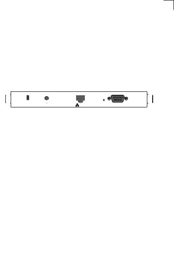
Rear Panel
|
|
|
|
|
|
|
|
|
|
|
|
|
|
|
|
|
|
|
|
|
Lock |
DC 5V |
|
|
POE In |
Reset |
Console |
|
|
Security Slot |
5 VDC |
RJ-45 Port, |
Reset |
Console |
|
Power Socket |
PoE Connector |
Button |
Port |
Component Description
Antennas
The access point includes integrated diversity antennas for wireless communications. A diversity antenna system uses two identical antennas to receive and transmit signals, helping to avoid multipath fading effects. When receiving, the access point checks both antennas and selects the one with the strongest signal. When transmitting, it will continue to use the antenna previously selected for receiving. The access point never transmits from both antennas at the same time.
The antennas transmit the outgoing signal as a toroidal sphere (doughnut shaped), with the coverage extending most in a direction perpendicular to the antenna. The antenna should be adjusted to an angle that provides the appropriate coverage for the service area. For further information, see “Positioning the Antennas” on 2-2.
LED Indicators
The access point includes four status LED |
|
|
|
|
|
|
indicators, as described in the following |
|
PWR |
Link |
11a |
11g |
|
figure and table. |
|
|
|
|
|
|
|
|
|
|
|
|
|
Power |
Ethernet |
802.11a |
802.11b/g |
|||
|
|
Link/Activity |
Wireless |
Wireless |
||
|
|
|
|
Link/Activity |
Link/Activity |
|
1-3

1 Introduction
LED |
Status |
Description |
PWR |
On |
Indicates that the system is working normally. |
|
|
|
|
Flashing |
Indicates running a self-test or loading the software program. |
|
|
|
|
Flashing (Prolonged) |
Indicates system errors. |
|
|
|
Link |
On |
Indicates a valid 10/100 Mbps Ethernet cable link. |
|
|
|
|
Flashing |
Indicates that the access point is transmitting or receiving data |
|
|
on a 10/100 Mbps Ethernet LAN. Flashing rate is proportional |
|
|
to network activity. |
11a |
On |
Indicates that the 802.11a radio is enabled. |
|
|
|
|
Flashing |
Indicates that the access point is transmitting or receiving data |
|
|
through wireless links. Flashing rate is proportional to network |
|
|
activity. |
|
Off |
Indicates that the 802.11a radio is disabled. |
|
|
|
11g |
On |
Indicates that the 802.11b/g radio is enabled. |
|
|
|
|
Flashing |
Indicates that the access point is transmitting or receiving data |
|
|
through wireless links. Flashing rate is proportional to network |
|
|
activity. |
|
Off |
Indicates that the 802.11b/g radio is disabled. |
|
|
|
Security Slot
The access point includes a Kensington security slot on the rear panel. You can prevent unauthorized removal of the access point by wrapping the Kensington security cable (not provided) around an unmovable object, inserting the lock into the slot, and turning the key.
Console Port
This port is used to connect a console device to the access point through a serial cable. This connection is described under “Console Port Pin Assignments” on page B-3. The console device can be a PC or workstation running a VT-100 terminal emulator, or a VT-100 terminal.
Ethernet Port
The access point has one 10BASE-T/100BASE-TX RJ-45 port that can be attached directly to 10BASE-T/100BASE-TX LAN segments. These segments must conform to the IEEE 802.3 or 802.3u specifications.
This port uses an MDI (i.e., internal straight-through) pin configuration. You can therefore use straight-through twisted-pair cable to connect this port to most network interconnection devices such as a switch or router that provide MDI-X ports. However, when connecting the access point to a workstation or other device that does not have MDI-X ports, you must use crossover twisted-pair cable.
The access point appears as an Ethernet node and performs a bridging function by moving packets from the wired LAN to remote workstations on the wireless infrastructure.
1-4

Features and Benefits 1
Note: The RJ-45 port also supports Power over Ethernet (PoE) based on the IEEE 802.3af standard. Refer to the description for the “Power Connector” for information on supplying power to the access point’s network port from a network device, such as a switch, that provides Power over Ethernet (PoE).
Reset Button
This button is used to reset the access point or restore the factory default configuration. If you hold down the button for less than 5 seconds, the access point will perform a hardware reset. If you hold down the button for 5 seconds or more, any configuration changes you may have made are removed, and the factory default configuration is restored to the access point.
Power Connector
The access point does not have a power switch. It is powered on when connected to the AC power adapter, and the power adapter is connected to a power source. The power adapter automatically adjusts to any voltage between 100-240 volts at 50 or 60 Hz. No voltage range settings are required.
The access point may also receive Power over Ethernet (PoE) from a switch or other network device that supplies power over the network cable based on the IEEE 802.3af standard.
Note that if the access point is connected to a PoE source device and also connected to a local power source through the AC power adapter, PoE will be disabled.
Features and Benefits
•Local network connection via 10/100 Mbps Ethernet ports or 54 Mbps wireless interface (supporting up to 128 mobile users)
•IEEE 802.11a, 802.11b, and 802.11g compliant
•Interoperable with multiple vendors based on the IEEE 802.11f protocol
•Advanced security through 64/128/152-bit Wired Equivalent Protection (WEP) encryption, IEEE 802.1X authentication via a RADIUS server, Wi-Fi Protected Access (WPA), and MAC address filtering features to protect your sensitive data and authenticate only authorized users to your network
•Provides seamless roaming within the IEEE 802.11a, 802.11b and 802.11g WLAN environment
•Scans all available channels and selects the best channel for each client based on the signal-to-noise ratio
1-5

1 Introduction
Applications
Wireless network products offer a high speed, reliable, cost-effective solution for wireless Ethernet client access to the network in applications such as:
•Remote access to corporate network information – E-mail, file transfer, and terminal emulation.
•Difficult-to-wire environments –
Historical or old buildings, asbestos installations, and open areas where wiring is difficult to employ.
•Frequently changing environments –
Retailers, manufacturers, and banks that frequently rearrange the workplace or change location.
•Temporary LANs for special projects or peak times –
Trade shows, exhibitions and construction sites that need temporary setup for a short time period. Retailers, airline and shipping companies that need additional workstations for a peak period. Auditors who require workgroups at customer sites.
•Access to databases for mobile workers –
Doctors, nurses, retailers, or white-collar workers who need access to databases while being mobile in a hospital, retail store, or an office campus.
•SOHO users –
SOHO (Small Office and Home Office) users who need easy and quick installation of a small computer network.
System Defaults
The following table lists some of the access point’s basic system defaults. To reset the access point defaults, use the CLI command “reset configuration” from the Exec level prompt.
Table 1-1. System Defaults
Feature |
Parameter |
Default |
|
|
|
Identification |
System Name |
SMC |
|
|
|
Administration |
User Name |
admin |
|
|
|
|
Password |
null |
|
|
|
General |
HTTP Server |
Enabled |
|
|
|
|
HTTP Server Port |
80 |
|
|
|
|
HTTPS Server |
Enabled |
|
|
|
|
HTTPS Server Port |
443 |
|
|
|
|
Web Redirect |
Disabled |
|
|
|
1-6
Loading...