


3B SCIENTIFIC® PHYSICS
Electrometer U8531408
Bedienungsanleitung
09/08 Hh
1 |
Steckplatz für SEG-Elemente |
7 |
Betriebsanzeige |
2 |
Eingangsbuchse IN für Faraday-Becher |
8 |
Offset-Einsteller des Elektrometers |
3 |
Eingangsbuchse IN für SEG-Elemente |
9 |
Massebuchse (Bezugspunkt) für den Ausgang |
4 |
Massebuchse (Bezugspunkt) für den Eingang |
10 |
Ausgangsbuchse OUT |
5 |
Anschlussbuchse für Haltestab mit 4-mm Bohrung |
11 |
Steckernetzgerät |
6 |
Hohlbuchse für 12 V AC-Steckernetzgerät |
|
|
1

1. Sicherheitshinweise
Elektrometer mit extrem hochohmigem, überspan- nungs-gefährdetem Spannungseingang:
•Maximalwert der Eingangsspannung von ± 8 V nicht überschreiten!
Eine höhere Spannung ist nur dann zulässig, wenn sicher gestellt ist, dass sie bei Berührung spannungsführender Teile unverzögert auf den oben angegebenen Wert oder auf niedrigere Werte herabgesetzt wird. Dies ist bei den im Text genannten Spannungsquellen gewährleistet.
•Keine Fremdspannungen an die Ausgangsbuchse (10) anschließen!
•Spannungsteilerschaltungen zur Messung von Spannungen über 10 V nur mit SEG-Kondensatoren bestücken, deren Spannungsfestigkeit für die anliegende Spannung ausreicht!
2. Beschreibung
Impedanzwandler mit extrem hohem Eingangswiderstand zur Messung kleinster Ladungen und kleinster Ströme.
Geeignet zur quasistatischen Messung von Spannungen bis ± 8 V, zur hochohmigen Messung von Spannungen über ± 8 V mit ohmschem Spannungsteiler, zur quasistatischen Messung von Spannungen über ± 8 V mit kapazitivem Spannungsteiler, zur Messung sehr kleiner Ströme mit hochohmigem Shuntwiderstand und zur Messung von Ladungen.
3. Technische Daten
Verstärkung: |
1,00 |
Eingangswiderstand: |
> 1012 Ω |
Ausgangswiderstand: |
< 1 kΩ |
Eingangsstrom: |
< 10 pA |
Eingangskapazität: |
< 50 pF |
Versorgungsspannung: |
12 V AC / 50-69 Hz / 100 mA |
Überspannungsfestigkeit |
|
für nicht berührungs- |
|
gefährliche Spannungen: |
1 kV (aus niederohmigen |
|
Quellen) |
|
10 kV (aus hochohmigen |
|
Quellen) |
Anschlüsse: |
4-mm-Sicherheitsbuchsen |
4.Bedienung
•12 V AC-Steckernetzgerät am Elektrometer anstecken, hiermit das Gerät einschalten.
•Geeigneten Spannungsmesser mit Skalennullpunkt Mitte-Funktion an der Ausgangsbuchse anschließen, z.B. Analog-Multimeter AM50 (U17450), VielfachMessgerät ESCOLA2 (U8531170), Vielfach-Messgerät ESCOLA10 (U8531160).
•Messbereich 10 V DC und Nullpunkt Mitte auswählen.
•Eingangsbuchse IN (3) mit 19-mm-Brückenstecker gegen Massebuchse (4) kurzschließen, oder
•Faraday-Becher (U8496460) in Eingangsbuchse (2) mit dem an der Erdungsbuchse (5) eingesteckten Haltestab mit 4-mm-Bohrung (U8430245) entladen (kurzschließen).
•Bei bestehendem Kurzschluss den Offset der Ausgangsspannung an Buchse (10) minimieren.
•Ausgewähltes Experiment zügig durchführen, bevor sich vagabundierende Ladungen auf dem Messeingang ansammeln.
•Vor Start eines neuen Experimentes wiederum Eingang kurzschließen und gegebenenfalls die Offseteinstellung korrigieren.
5.Versuchsbeispiel
Messung von Ladungen in der Elektrostatik
Benötigte Geräte:
1 |
Elektrometer |
U8531408 |
1 |
Analog-Multimeter AM50 |
U17450 |
1 |
Faraday-Becher |
U8496460 |
1 |
Kondensator 10 nF, 160 V |
U8403501 |
2 |
Reibstäbe |
U11053 |
1 |
Exp.-Kabel, 75 cm |
U13800 |
1 |
Haltestab mit 4-mm-Bohrung |
U8430245 |
1 |
Tuch, zum Reiben der Stäbe |
|
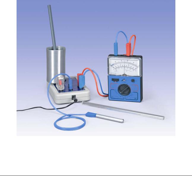
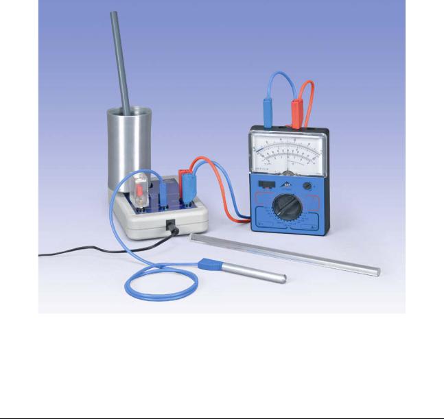
•Versuchsaufbau gemäß Fig. 1.
•Den Faraday-Becher und den 10 nF-Kondensator in die hierfür vorgesehenen 4-mm-Buchsen einstecken.
•Das Multimeter an der Ausgangsbuchse OUT (10) und der korrespondierenden Massebuchse (9) anschließen.
•Am Multimeter den Messbereich 10 V DC wählen.
•Das Experimentierkabel in die Anschlussbuchse für den Haltestab (5) und in die 4-mm-Bohrung des Haltestabs einstecken.
•Den Haltestab in der einen Hand halten und hiermit
– ohne ihn los zu lassen – den Faraday-Becher entladen.
2
•Mit der anderen Hand den Versuchskörper (z.B. den geriebenen Stab) zur Erfassung seiner gesamten Ladung in den feldfreien Innenraum des FaradayBechers eintauchen und die Ladung an der Innenseite des Bechers „abstreifen“.
•Die abgegebene Ladung gemäß der nachfolgenden Beziehungen und Gleichungen berechnen.
Zwischen der Ladung Q und der Spannung U eines Kondensators mit der Kapazität C besteht der Zusammenhang:
Q =C U
Wegen UOUT = UIN ist die Ausgangsspannung des Elektrometers ein Maß für die Ladung Q:
Q=UOUT C
•Mit der bekannten Kapazität C = 10 nF des Kondensators U8403501 kann nunmehr die Ladung ausgerechnet werden.
Fig. 1 Versuchsaufbau zur Messung von Ladungen in der Elektrostatik
Elwe Didactic GmbH • Steinfelsstr. 6 • 08248 Klingenthal • Deutschland • www.elwedidactic.com 3B Scientific GmbH • Rudorffweg 8 • 21031 Hamburg • Deutschland • www.3bscientific.com Technische Änderungen vorbehalten
© Copyright 2008 3B Scientific GmbH

3B SCIENTIFIC® PHYSICS
Electrometer U8531408
Instruction sheet
09/08 Hh
1 |
Docking point for SEG elements |
7 |
“On” indicator light |
2 |
Input socket “IN” for Faraday cup |
8 |
Electrometer offset adjuster |
3 |
Input socket “IN” for SEG elements |
9 |
Earth socket (reference point) for output |
4 |
Earth socket (reference point) for input |
10 |
Output socket “OUT” |
5 |
Connection socket for handling rod with 4 mm hole |
11 |
12 V AC mains adapter |
6 |
Recessed socket for 12 V AC mains adapter |
|
|
1

1. Safety instructions
The ultra-high-resistance input circuit of the electrometer can be damaged by applying an excessive voltage:
•Do not exceed the maximum input voltage of ± 8 V!
A higher voltage is only permissible with the condition that if a person touches conducting parts it is instantly reduced to the above or a lower value. The voltage sources mentioned in this instruction sheet fulfil that condition.
•Do not connect any external voltage source to the output socket (10)!
•If a capacitative voltage-divider circuit is used to measure voltages above 10 V, it must be provided with an SEG capacitor that can withstand the full applied voltage!
2. Description
Impedance-changer with an extremely high input resistance for measuring very small charges and very small currents.
It is suitable for quasi-static measurement of voltages up to ± 8 V, for high-resistance measurement of voltages above ± 8 V using a resistive voltage divider, for quasistatic measurement of voltages above ± 8 V using a capacitative voltage divider, for measurement of very small currents using a high-resistance shunt, and for measurement of charges.
3. Technical data
Amplification factor: |
1.00 |
Input resistance: |
> 1012 Ω |
Output resistance: |
< 1 kΩ |
Input current: |
< 10 pA |
Input capacitance: |
< 50 pF |
Supply voltage: |
12 V AC / 50-69 Hz / |
|
100 mA |
Overvoltage tolerated for |
|
voltage sources safe against |
|
accidental contact: |
1 kV (sources with low |
|
output resistance) |
|
10 kV (sources with |
|
high output resistance) |
Connections: |
4 mm safety sockets |
4.Operation
•Plug the 12 V AC adaptor into the electrometer and switch the instrument on.
•Connect a suitable voltage meter with a mid-scale zero-setting adjustment, such as analogue multimeter AM50 (U17450), multimeter ESCOLA2 (U8531170), or multimeter ESCOLA10 (U8531160), to the output sockets of the multimeter.
•Select the 10 V DC range and set the zero point at the middle of the scale.
•Short-circuit the “IN” (3) input socket to the earth socket (4) with a 19 mm bridging plug, or:
•Discharge (short-circuit) the Faraday cup (U8496460) that is plugged into the input socket (2) by using the handling rod with 4 mm hole (U8430245) that is connected to the earth socket (5).
•While maintaining the short-circuit, adjust the offset of the output voltage at socket (10) to a minimum.
•Quickly carry out the measurement for the chosen experiment, before there is time for stray charges to build up at the input being measured.
•Before starting a new experiment, short-circuit the input to earth again, and if necessary readjust the offset.
5.Sample experiment
Measuring charges in electrostatics
Apparatus needed:
1 |
Electrometer |
U8531408 |
1 |
Analogue multimeter AM50 |
U17450 |
1 |
Faraday cup |
U8496460 |
1 |
Capacitor, 10 nF, 160 V |
U8403501 |
2 |
Friction rods |
U11053 |
1 |
Experiment lead, 75 cm |
U13800 |
1 |
Handling rod with 4 mm hole |
U8430245 |
1 |
Cloth for rubbing friction rods |
|
•Set up the experiment as shown in Figure 1.
•Plug the Faraday cup and the 10 nF capacitor into the appropriate 4 mm sockets.
•Connect the multimeter to the output socket “OUT” (10) and the corresponding earth socket (9).
•Select the 10 V DC range on the multimeter.
•Plug the experiment lead into the socket for the handling rod (5) and into the 4 mm hole in the rod.
•Take the handling rod in one hand and, without releasing it, discharge the Faraday cup.
•With the other hand, immerse the test object (e.g. the friction rod after rubbing) into the field-free interior of the Faraday cup so that the whole of its
2
charge is within, and “wipe” the charge onto the inner surface of the cup.
•Use the relationships given below to calculate the charge that has been transferred.
•For a capacitor of capacitance C, the relationship between the charge Q and the voltage U is:
Q=C U
•Since UOUT = UIN, the output voltage from the electrometer gives a measure of the charge Q:
Q=UOUT C
•The capacitor U8403501 has the known capacitance C = 10 nF, and therefore the charge can be calculated.
Fig. 1 Experiment set-up for measuring charges in electrostatics
Elwe Didactic GmbH • Steinfelsstr. 6 • 08248 Klingenthal • Germany • www.elwedidactic.com 3B Scientific GmbH • Rudorffweg 8 • 21031 Hamburg • Germany • www.3bscientific.com Technical amendments are possible
© Copyright 2008 3B Scientific GmbH
 Loading...