


TV PLASMA TV LCD
DVB is a registered trademark of the DVB Project
LCD TV MODELS |
PLASMA TV MODELS |
32LC2D |
42PC1DG |
37LC2D |
42PC1DV |
42LC2D |
50PC1D |
|
60PC1D |
Please read Information Manual included together before reading this manual and operating your set.
P/NO : 38289U0569A (0608-REV05)
9U0569A-1 Rev05-ING 06/8/23 3:27 PM Page 1 |
R
TruSurround XT
 is a trademark of SRS Labs, Inc.
TruSurround XT technology is incorporated under license from SRS Labs, Inc.
Manufactured under license from Dolby Laboratories. “Dolby” and the double-D symbol are trademarks of Dolby Laboratories.
HDMITM, the HDMI logo and High-Definition Multimedia Interface is a trademark or registered trademark of HDMI Licensing."
LG's own special digital image generator. It consists of full digital image processor, APM mode & 6 different main picture quality factors.
1
9U0569A-1 Rev05-ING 06/8/23 3:27 PM Page 2
CONTENTS |
|
|
|
INTRODUCTION |
|
|
Accessories . . . . . . . . . . . . . . . . . . . . . . . . . . . . . . . . . . . . . . . . . . . . . . . . |
. . . . . . 5 |
|
Controls / Connection Options (42PC1D*, |
|
|
50PC1D*, 60PC1D*) . . . . . . . . . . . . . . . . . . . . . . . . . . . . . . . . . |
. . . 6-7 |
|
Controls / Connection Options |
|
|
(32/37/42LC2D*) . . . . . . . . . . . . . . . . . . . . . . . . . . . . . . . . . . . . . |
. . . 8-9 |
|
Remote Control Key Functions . . . . . . . . . . . . . . . . . . . . |
10-11 |
CONTENTS |
|
|
|
INSTALLATION |
|
|
Stand Installation . . . . . . . . . . . . . . . . . . . . . . . . . . . . . . . . . . . . . . . |
12-13 |
|
Wire Arrangement . . . . . . . . . . . . . . . . . . . . . . . . . . . . . . . . . . . . . . |
14-15 |
|
Attaching the TV to a wall . . . . . . . . . . . . . . . . . . . . . . . . . . . |
. . . . . 16 |
|
Desktop Pedestal Installation . . . . . . . . . . . . . . . . . . . . . . . |
. . . . . 17 |
|
Swivel Stand . . . . . . . . . . . . . . . . . . . . . . . . . . . . . . . . . . . . . . . . . . . . . . . |
. . . . . 17 |
CONNECTIONS & SETUP
Antenna Connection . . . . . . . . . . . . . . . . . . . . . . . . . . . . . . . . . . . . . . . . 18
Antenna Loop Through Socket . . . . . . . . . . . . . . . . . . . . . . . . . 19
HDSTB Setup . . . . . . . . . . . . . . . . . . . . . . . . . . . . . . . . . . . . . . . . . . . 20-22
VCR Setup . . . . . . . . . . . . . . . . . . . . . . . . . . . . . . . . . . . . . . . . . . . . . . . 23-24
AV Out Setup . . . . . . . . . . . . . . . . . . . . . . . . . . . . . . . . . . . . . . . . . . . . . . . . . 25
Digital Audio Output . . . . . . . . . . . . . . . . . . . . . . . . . . . . . . . . . . . . . . . 26
External A/V Source Setup . . . . . . . . . . . . . . . . . . . . . . . . . . . . . . 27
DVD Setup . . . . . . . . . . . . . . . . . . . . . . . . . . . . . . . . . . . . . . . . . . . . . . . . 28-29
PC Setup . . . . . . . . . . . . . . . . . . . . . . . . . . . . . . . . . . . . . . . . . . . . . . . . . . 30-33
BASIC OPERATION
Turning the TV On . . . . . . . . . . . . . . . . . . . . . . . . . . . . . . . . . . . . . . . . . . 34 Initializing setup . . . . . . . . . . . . . . . . . . . . . . . . . . . . . . . . . . . . . . . . . . . . . . 34 Volume Adjustment . . . . . . . . . . . . . . . . . . . . . . . . . . . . . . . . . . . . . . . . . 35 Programme Selection . . . . . . . . . . . . . . . . . . . . . . . . . . . . . . . . . . . . . . . 35
SPECIAL FUNCTIONS
PIP/POP/Twin Picture
- Watching PIP/POP/Twin Picture . . . . . . . . . . . . . . . . . . . . . 36
- Selecting an Input Signal Source
for PIP/Twin Picture . . . . . . . . . . . . . . . . . . . . . . . . . . . . . . . . . . . . . . 37
- TV Program Selection for PIP . . . . . . . . . . . . . . . . . . . . . . . . . 37
- Moving the PIP sub picture . . . . . . . . . . . . . . . . . . . . . . . . . . . . 37 - Swapping PIP/Twin Picture . . . . . . . . . . . . . . . . . . . . . . . . . . . . 38
- Adjusting Main and Sub Picture Sizes
for Twin Picture . . . . . . . . . . . . . . . . . . . . . . . . . . . . . . . . . . . . . . . . . . . . . 38
- POP(Picture-out-of-Picture: Programme Scan) . . . . . . . 39
TELETEXT
Switch On/Off . . . . . . . . . . . . . . . . . . . . . . . . . . . . . . . . . . . . . . . . . . . . . . . . 40
Simple Text . . . . . . . . . . . . . . . . . . . . . . . . . . . . . . . . . . . . . . . . . . . . . . . . . . . . . 40
Top Text . . . . . . . . . . . . . . . . . . . . . . . . . . . . . . . . . . . . . . . . . . . . . . . . . . . . . . . . . 40
Fastext . . . . . . . . . . . . . . . . . . . . . . . . . . . . . . . . . . . . . . . . . . . . . . . . . . . . . . . . . . . . 41
Special Teletext . . . . . . . . . . . . . . . . . . . . . . . . . . . . . . . . . . . . . . . . . . . . . . . 41
EPG (Electronic Programme Guide) |
|
- Switch on/off EPG . . . . . . . . . . . . . . . . . . . . . . . . . . . . . . . . . . . . . . . . |
42 |
- Select a programme . . . . . . . . . . . . . . . . . . . . . . . . . . . . . . . . . . . . . . |
42 |
2
9U0569A-1 Rev05-ING 06/8/23 3:27 PM Page 3
TV MENU
On Screen Menus Selection and Adjustment . . . . 43
Setup(Programme)
Auto Programme Tuning
Manual Programme Tuning . . . . . . . . . . . . . . . . . . . . . . . . . 45-46 Fine tuning (In Analogue mode only) . . . . . . . . . . . . . . . . 47 Assigning a station name (In Analogue mode only) . . . . 48
Programme Edit . . . . . . . . . . . . . . . . . . . . . . . . . . . . . . . . . . . . . . . . . 49-50
Calling up the Programme Table . . . . . . . . . . . . . . . . . . . . . . . 51 Digital signal strength (In Digital mode only) . . . . 52 Booster (In Digital mode only) . . . . . . . . . . . . . . . . . . . . . . . . . 53
Video Adjustment
Picture Status Memory (PSM) . . . . . . . . . . . . . . . . . . . . . . . . . 54
Adaptive Picture Mode (APM) . . . . . . . . . . . . . . . . . . . . . . . . . 55
Brightness Adjustment . . . . . . . . . . . . . . . . . . . . . . . . . . . . . . . . . . . . 55
Manual Picture Control (PSM-User Option) . . . . . 56
XD . . . . . . . . . . . . . . . . . . . . . . . . . . . . . . . . . . . . . . . . . . . . . . . . . . . . . . . . . . . . . . . . . 57
Colour Temperature Control . . . . . . . . . . . . . . . . . . . . . . . 58-59
- Auto Colour Temperature Control . . . . . . . . . . . . . . . . . . 58
- Manual Colour Temperature Control . . . . . . . . . . . . . . 59
Advanced . . . . . . . . . . . . . . . . . . . . . . . . . . . . . . . . . . . . . . . . . . . . . . . . . 60-61
- Cinema . . . . . . . . . . . . . . . . . . . . . . . . . . . . . . . . . . . . . . . . . . . . . . . . . . . . . . . . 60
- Black Level . . . . . . . . . . . . . . . . . . . . . . . . . . . . . . . . . . . . . . . . . . . . . . . . . . . . 61
Video Preset . . . . . . . . . . . . . . . . . . . . . . . . . . . . . . . . . . . . . . . . . . . . . . . . . . 62
Audio Adjustment
Sound Status Memory (SSM) . . . . . . . . . . . . . . . . . . . . . . . . . . 63
Manual Sound Control (SSM-User Option) . . . . 64-65
Auto Volume Leveller (AVL) . . . . . . . . . . . . . . . . . . . . . . . . . . . . . . 66
Balance . . . . . . . . . . . . . . . . . . . . . . . . . . . . . . . . . . . . . . . . . . . . . . . . . . . . . . . . . . 67
TV Speakers On/Off Setup . . . . . . . . . . . . . . . . . . . . . . . . . . . . . . 68
Stereo Reception (In Analogue mode only) . . . . . . 69
Sound output selection . . . . . . . . . . . . . . . . . . . . . . . . . . . . . . . . . . . 69
Time Setting
Auto Clock Setup . . . . . . . . . . . . . . . . . . . . . . . . . . . . . . . . . . . . . . . . . . . . 70
Manual Clock Setup . . . . . . . . . . . . . . . . . . . . . . . . . . . . . . . . . . . . . . . . 71
On/Off Time Setup . . . . . . . . . . . . . . . . . . . . . . . . . . . . . . . . . . . . . . . . 72
Sleep Timer . . . . . . . . . . . . . . . . . . . . . . . . . . . . . . . . . . . . . . . . . . . . . . . . . . . . 73
Auto Sleep . . . . . . . . . . . . . . . . . . . . . . . . . . . . . . . . . . . . . . . . . . . . . . . . . . . . . . 74
Optional Features |
|
Main Picture Source Selection . . . . . . . . . . . . . . . . . . . . . . . . . . |
75 |
Subtitle (In Digital mode only) . . . . . . . . . . . . . . . . . . . . . . . . . |
76 |
Child Lock . . . . . . . . . . . . . . . . . . . . . . . . . . . . . . . . . . . . . . . . . . . . . . . . . . . . . |
77 |
Picture Format . . . . . . . . . . . . . . . . . . . . . . . . . . . . . . . . . . . . . . . . . . . . |
78 |
XD Demo . . . . . . . . . . . . . . . . . . . . . . . . . . . . . . . . . . . . . . . . . . . . . . . . . . . |
79 |
ISM (Image Sticking Minimization) Method (42PC1D*, |
|
50PC1D*, 60PC1D* only) . . . . . . . . . . . . . . . . . . . . . . . . . . . . . . . . |
80 |
Low Power (42PC1D*, 50PC1D*, 60PC1D* only) . . |
81 |
Lock Adjustment
Setting Up Your password . . . . . . . . . . . . . . . . . . . . . . . . . . . . . . . . 82 Lock System . . . . . . . . . . . . . . . . . . . . . . . . . . . . . . . . . . . . . . . . . . . . . . . . . . . . 82 Set Password . . . . . . . . . . . . . . . . . . . . . . . . . . . . . . . . . . . . . . . . . . . . . . . . . . 83 Block Programme . . . . . . . . . . . . . . . . . . . . . . . . . . . . . . . . . . . . . . . . . . . . 84
Parental Guidance (In Digital mode only) . . . . . . . . . 85
Aux. Block . . . . . . . . . . . . . . . . . . . . . . . . . . . . . . . . . . . . . . . . . . . . . . . . . . . . . . . 85
APPENDIX
External Control Device Setup . . . . . . . . . . . . . . . . . . . .86-92
IR Codes . . . . . . . . . . . . . . . . . . . . . . . . . . . . . . . . . . . . . . . . . . . . . . . . .93-94
Programming the Remote Control . . . . . . . . . . . . . . . . . . |
95 |
Programming Codes . . . . . . . . . . . . . . . . . . . . . . . . . . . . . . . . . 96-97
Troubleshooting Checklist . . . . . . . . . . . . . . . . . . . . . . . . . . 98-99
Product Specifications . . . . . . . . . . . . . . . . . . . . . . . . . . . . . . . . . . . 100
CONTENTS
After reading this manual, keep it handy for future reference. |
3 |
9U0569A-1 Rev05-ING 06/8/23 3:27 PM Page 4
INTRODUCTION
What is a Plasma TV?
Using plasma is the best way to achieve flat panel displays with excellent image quality and large screen sizes that are easily viewable. The Plasma TV can be thought of as a descendant of the neon lamp and or a series of fluorescent lamps.
INTRODUCTION |
How does it work? |
phosphors are the same types used in Cathode Ray |
|
|
Plasma TV is an array of cells, known as pixels, which |
|
are comprised of three sub-pixels, corresponding to |
|
the colors red, green, and blue. Gas in a plasma state |
|
is used to react with phosphors in each sub-pixel to |
|
produce colored light (red, green, or blue). These |
|
Tube (CRT) devices such as televisions and common |
|
computer monitors. |
|
Plasma TV offers a rich, dynamic display because |
|
each sub-pixel is individually controlled by advanced |
|
electronics to produce over 16 million different col- |
|
ors. This means that you get perfect images that are |
|
easily viewable in a display that is fewer than five |
|
inches thick. |
|
160° - Wide angle range of vision |
|
Your flat panel plasma screen offers an exceptionally |
|
broad viewing angle of over 160 degrees. This means |
|
that the display is clear and visible to viewers any- |
|
where in the room. |
|
Wide Screen |
|
The wide screen offers a theater-like experience in |
|
your own home. |
|
Multimedia |
|
Connect your plasma display to a PC and use it for |
|
conferencing, games, and Internet browsing. The |
|
Picture-in-Picture feature allows you to view your PC |
|
and video images simultaneously. |
|
Versatile |
|
The light weight and thin size makes it easy to install |
|
your plasma display in a variety of locations where |
|
conventional TVs do not fit. |
|
The Plasma TV Manufacturing Process: a few |
|
minute colored dots may be present on the |
|
Plasma TV screen |
|
The Plasma TV is composed of 0.9 to 2.2 million |
|
|
cells. A few cell defects will normally occur in the Plasma TV manufacturing process. Several tiny, minute colored dots visible on the screen should be acceptable. This also occurs in other Plasma TV manufacturers' products. The tiny dots appearing does not mean that this Plasma TV is defective. Thus a few cell defects are not sufficient cause for the Plasma TV to be exchanged or returned. Our production technology minimizes these cell defects during the manufacture and operation of this product.
Cooling Fan Noise-This feature is not available for all models.
In the same way that a fan is used in a PC computer to keep the CPU (Central Processing Unit) cool, the Plasma TV is equipped with cooling fans to cool the Monitor and improve its reliability. Therefore, a certain level of noise could occur while the fans are operating and cooling the Plasma TV.
The fan noise doesn't have any negative effect on the Plasma TV's efficiency or reliability. The noise from these fans is normal during the operation of this product. We hope you understand that a certain level of noise from the cooling fans is acceptable and is not sufficient cause for the Plasma TV to be exchanged or returned.
FOR LCD TV
If the TV feels cold to the touch, there may be a small “flicker” when it is turned on. This is normal, there is nothing wrong with TV.
Some minute dot defects may be visible on the screen, appearing as tiny red, green, or blue spots. However, they have no adverse effect on the monitor's performance.
Avoid touching the LCD screen or holding your finger(s) against it for long periods of time. Doing so may produce some temporary distortion effects on the screen.
On Disposal
a.The fluorescent lamp used in this product contains a small amount of mercury.
b.Do not dispose of this product with general household waste.
c.Disposal of this product must be carried out in accordance to the regulations of your local authority.
4
9U0569A-1 Rev05-ING 06/8/23 3:27 PM Page 5
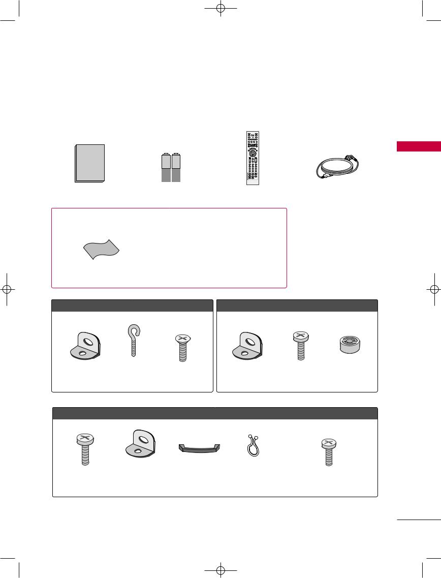
ACCESSORIES
Ensure that the following accessories are included with your product. If an accessory is missing, please contact the dealer where you purchased the product.
INPUT
D/A POWER TV
INPUT |
DVD |
ARC  VCR
VCR
TEXT PIP GUIDE INFO
|
|
LIST |
MENU |
I/II |
Owner's Manual |
|
EXIT |
|
SLEEP |
|
|
OK |
|
|
1.5V |
1.5V |
VOL |
|
PR |
74 |
85 |
96 |
||
|
|
1 |
2 |
3 |
|
|
APM |
0 |
FAV |
|
|
SIZE |
INDEX |
TIME |
|
|
REVEAL |
PIP PR + |
PIP PR - |
|
|
PIP INPUT |
SWAP |
|
Owner’s Manual |
Batteries |
Remote Control |
Power Cord |
37LC2D*/42LC2D*
/42PC1DG/50PC1D only
Polishing Cloth
Polish the screen with the cloth.
*Slightly wipe stained spot on the exterior only with the polishing cloth for the product exterior if there is stain or fingerprint on surface of the exterior.
*Do not wipe roughly when removing stain. Please be cautions of that excessive power may cause scratch or discoloration.
INTRODUCTION
4-bolts |
4-Ring Spacer |
(Refer to p.13) |
2-Wall Brackets |
For 32LC2D*/37LC2D*/42LC2D*
32LC2D* only
2-TV Bracket Bolts 2-TV Brackets, |
Cable Management |
Twister Holder |
4-bolts for stand assembly |
2-Wall Brackets |
(Refer to p.15) |
Arrange the wires |
See below for detail information. |
|
|
with the twister holder. |
(Refer to p.12) |
5
9U0569A-1 Rev05-ING 06/8/23 3:27 PM Page 6
INTRODUCTION
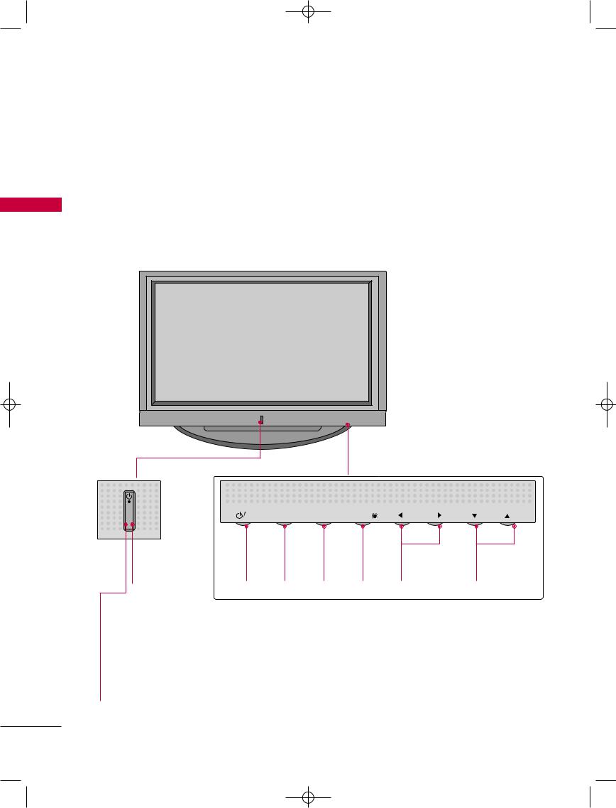
CONTROLS
■ Here shown may be somewhat different from your TV.
Front Panel Controls
This is a representation of the front panel of model 42PC1D*, 50PC1D*, 60PC1D*.
INTRODUCTION
Remote
Control
Sensor
Power Standby
Indicator
Illuminates red in standby mode.
When the TV is turned on, the indicator blinks white and then illuminates white before the picture is displayed.
INPUT |
MENU |
OK |
VOL |
PR |
POWER |
INPUT |
MENU |
OK |
VOLUME |
PROGRAMME |
Button |
Button |
Button |
Button |
F G |
E D |
|
|
|
|
( , )Buttons |
( , )Buttons |
6
9U0569A-1 Rev05-ING 06/8/23 3:27 PM Page 7
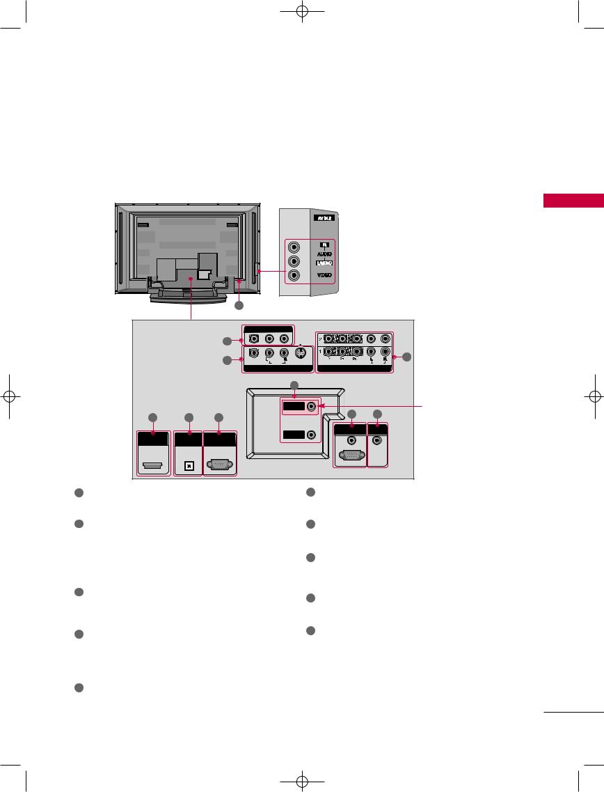
CONNECTION OPTIONS
This manual explains the features available on the 42PC1D*, 50PC1D*, 60PC1D*.
■ Here shown may be somewhat different from your TV.
Back Connection Panel
|
|
|
|
|
|
|
AUDIO Input |
|
|
|
|
|
|
|
|
|
Connections are available for listening to |
||
|
|
|
|
|
|
|
stereo sound from an external device. |
||
|
|
|
|
|
|
|
VIDEO Input |
|
|
|
|
|
|
|
|
|
Connects the video signal from a video |
||
|
|
|
|
|
|
|
device. |
|
|
|
|
|
|
10 |
|
|
|
|
|
|
|
|
|
|
AV OUT |
|
|
|
|
|
|
|
1 |
|
|
|
|
|
|
|
|
|
2 |
|
(MONO) |
S-VIDEO |
VIDEO |
3 |
|
|
|
|
VIDEO |
AUDIO |
|
|
|||
|
|
|
|
|
AV IN 1 |
|
COMPONENT IN |
|
|
|
|
|
|
|
|
7 |
|
|
|
|
|
|
|
|
A |
A |
|
|
* ANTENNA OUT |
|
5 |
|
6 |
|
|
|
8 |
9 |
This jack is not available |
|
|
|
|
|
|
|
|||
|
|
|
|
|
|
|
RGB IN |
REMOTE |
for all models. |
|
|
|
RS-232C IN |
|
ANTENNA |
|
CONTROL IN |
|
|
HDMI/DVI IN |
DIGITA |
OUT |
|
|
IN |
|
|
|
|
|
O |
|
(CONTROL & SERVICE) |
|
|
|
AUDIO (RGB/DVI) |
|
|
|
|
|
|
|
|
|
|
|
|
|
|
|
|
|
|
|
RGB (PC/DTV) |
|
|
1
Connect a second TV or monitor.
2
Connect audio/video output from an externa
device to these jacks. |
|
|
S-VIDEO |
|
|
Connect S-Video out |
S-VIDEO |
. |
3COMPONENT IN
Connect a component video/audio device to these jacks.
4HDMI/DVI IN
Connect a HDMI signal.
Or DVI(VIDEO)signal to the this port with a HDMI to DVI cable.
5DIGITAL AUDIO OUT OPTICAL
Connect digital audio from various types of equipment. Note: In standby mode, these ports do not work.
6RS-232C IN (CONTROL &SERVICE) PORT
Connect to the RS-232C port on a PC.
ANTENNA IN / ANTENNA OUT
Connect cable signals to this jack.
8RGB/AUDIO IN
Connect the output from a settop box or PC to the appropriate input port.
9Remote Control Port
Connect your wired remote control.
10 Power Cord Socket
For operation with AC power.
Caution: Never attempt to operate the TV on DC power.
INTRODUCTION
7
9U0569A-1 Rev05-ING 06/8/23 3:27 PM Page 8
INTRODUCTION
INTRODUCTION
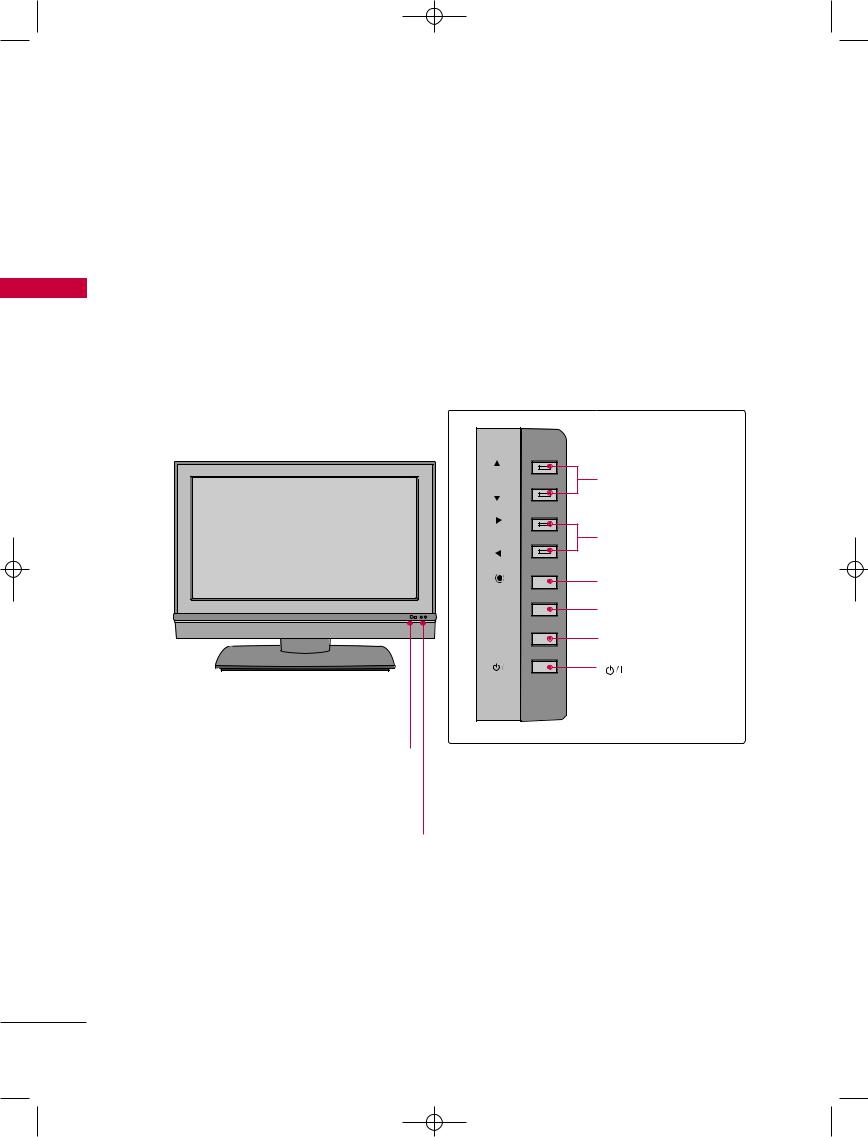
CONTROLS
This is a front panel of 32LC2D*, 37LC2D*, 42LC2D*.
■ Here shown may be somewhat different from your TV.
Front Panel Controls
|
PR |
PROGRAMME |
|
|
(D,E)Button |
|
VOL |
VOLUME (F,G) |
|
|
Button |
|
OK |
OK Button |
|
|
|
R |
MENU |
MENU Button |
|
INPUT |
INPUT Button |
|
|
(POWER) Button |
Remote Control Sensor
Power Standby Indicator
Illuminates red in standby mode.
When the TV is turned on, the indicator blinks white and then illuminates white before the picture is displayed.
8
9U0569A-1 Rev05-ING 06/8/23 3:27 PM Page 9
CONNECTION OPTIONS
This is the back panel of 32LC2D*, 37LC2D*, 42LC2D*.
■ Here shown may be somewhat different from your TV.
Back Connection Panel 37/42LC2D* |
32LC2D* |
|
R |
AUDIO |
L/MONO |
AC IN |
|
AV IN 2
10
AUDIO Input
Connections are available for listening to stereo sound from an external device.
Connects the video signal from a video device.
R
AUDIO L/MONO
VIDEO
AV IN 2
|
|
|
AV OUT |
|
|
|
|
|
1 |
|
|
|
|
|
|
2 |
(MONO) |
|
|
3 |
|
|
S-VIDEO |
VIDEO |
|
||
|
|
VIDEO |
AUDIO |
|
||
|
|
|
AV IN 1 |
|
COMPONENT I |
|
4 |
5 |
6 |
|
|
8 |
9 |
|
7 |
|
|
|||
|
|
|
|
|
|
|
|
|
|
|
|
RGB IN |
REMOTE |
|
|
|
|
|
CONTROL IN |
|
|
DIGITAL AUDIO |
RS-232C IN |
|
|
|
|
HDMI/DVI IN |
|
ANTENNA |
|
|
||
|
OUT |
(CONTROL & SERVICE) |
|
OUT |
AUDIO (RGB/DVI) |
|
|
|
|
|
|
|
|
|
OPTICAL |
|
|
ANTENNA |
|
|
|
|
|
|
IN |
|
|
|
|
|
|
|
RGB (PC/DTV) |
|
1
Connect a second TV or monitor.
2
Connect audio/video output from an externa device to these jacks.
S-VIDEO
Connect S-Video out from an S-VIDEO device.
3COMPONENT IN
Connect a component video/audio device to these jacks.
4HDMI/DVI IN
Connect a HDMI signal.
Or DVI(VIDEO)signal to the this port with a HDMI to DVI cable.
5DIGITAL AUDIO OUT
Connect digital audio from various types of
. Note: In standby mode, these ports do not work.
RS-232C IN (CONTROL &SERVICE) PORT
Connect to the RS-232C port on a PC.
7ANTENNA IN / ANTENNA OUT
Connect cable signals to this jack.
8RGB/AUDIO IN
Connect the output from a settop box or PC to the appropriate input port.
9Remote Control Port
Connect your wired remote control.
10Power Cord Socket
For operation with AC power.
Caution: Never attempt to operate the TV on DC power.
INTRODUCTION
9
9U0569A-1 Rev05-ING 06/8/23 3:27 PM Page 10
INTRODUCTION
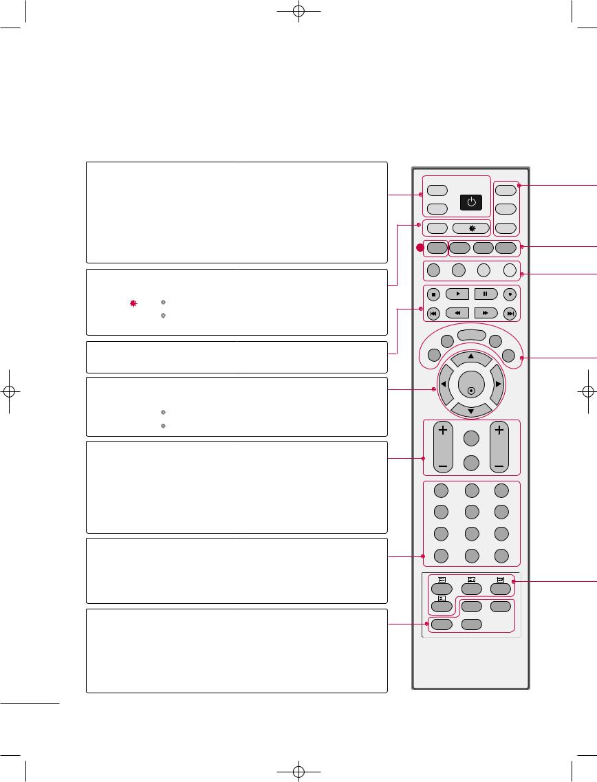
REMOTE CONTROL KEY FUNCTIONS
When using the remote control, aim it at the remote control sensor on the TV.
D/A INPUT Selects digital or analogue mode.
|
(Digital TV / |
|
|
|
Analogue TV) |
External input modes rotate in regular sequence: Digital, |
|
|
|||
|
INPUT |
||
INTRODUCTION |
|||
|
Analogue, AV1-2, Component 1-2, RGB-DTV (or RGB- |
||
|
|
||
|
|
PC), HDMI/DVI. |
|
|
POWER Switches the set between ON and STANDBY. |
||
|
ARC |
Selects your desired picture format. G p.78 |
|
|
+/- |
Adjusts brightness on screen. G p.55 |
|
|
|
It returns to the default settings brightness by changing |
|
|
|
mode source. |
|
VCR/DVD Control some video cassette recorders or DVD players control buttons ("RECORD" button is not available for DVD player).
OK Accepts your selection or displays the current mode.
THUMBSTICK |
Adjusts menu settings. |
|
(Up/Down/Left |
Selects menu item. |
|
Right/OK) |
||
|
VOLUME +/- Increase/decrease the sound level.
Q.VIEW Returns to the previously viewed programme.
MUTE Switches the sound on or off.
Programme +/- Selects a programme.
NUMBER button
APM Concurrently, compare with the Dynamic, Standard, Mild,
User1 and User2 on the screen. G p.55
FAV (FAVOURITE) Displays the selected favourite programmes.
PIP PR +/- Selects a programme for the sub picture.G p.37
PIP INPUT Selects the input mode for the sub picture.G p.37
SWAP Alternates between main and sub picture in PIP/Twin picture mode.G p.38
INPUT |
|
|
D/A |
POWER |
TV |
INPUT |
|
DVD |
ARC |
|
VCR |
1 TEXT PIP GUIDE INFO
LIST |
MENU |
I/II |
|
|
|
EXIT |
|
SLEEP |
OK
|
Q.VIEW |
VOL |
PR |
|
MUTE |
1 |
2 |
3 |
4 |
5 |
6 |
7 |
8 |
9 |
APM |
0 |
FAV |
SIZE |
INDEX |
TIME |
? |
|
|
REVEAL |
PIP PR + |
PIP PR - |
PIP INPUT |
SWAP |
|
10
9U0569A-1 Rev05-ING 06/8/23 3:27 PM Page 11
TV, DVD, VCR, Selects the remote operating mode: TV, VCR, DVD. Select other operating modes, for the remote to operate external devices.
PIP Switches to PIP, POP and Twin picture modes or off mode. G p.36-39
GUIDE Shows a programme schedule. G p.42
INFO Shows the present screen information.
COLOURE They are used as per the indications or functions displayed on the TV screen in the case of Button Text displays (Teletext, EPG) and programme edit.
EXIT Returns to TV viewing from any menu.
LIST Displays the programme table. G p.51
MENU Selects a menu.
I/II Selects the sound output or the audio mode. G p.69
SLEEP Sets the sleep timer. G p.73
1
BUTTONS Text button is used to enable teletext services while other buttons are for teletext functions. * For further details, see the ‘Teletext’ section. G p.40-41
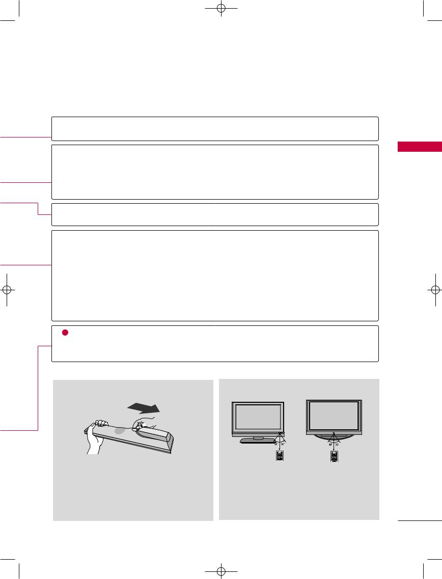
Installing Batteries |
Remote control effective range |
■Open the battery compartment cover on the back side and install the batteries matching correct polarity (+with +,-with -).
■Install two 1.5V AA batteries. Don’t mix old or used batteries with new ones.
■Close cover.
■Use a remote control up to 7 meters distance and 30 degree (left/right) within the receiving unit scope.
■Dispose of used batteries in a recycle bin to preserve environment.
INTRODUCTION
11
9U0569A-1 Rev05-ING 06/8/23 4:06 PM Page 12
INSTALLATION
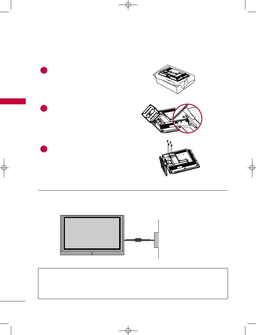
STAND INSTALLATION (FOR 32LC2D*)
INSTALLATION
1 Carefully place the product screen side down on a cushioned surface that will protect product and screen from damage.
2Place the
product as
3 |
Install the 4 bolts provided securely, in the back of |
|
the product. |
■This manual explains the features available on the 42PC1D*, 50PC1D*, 60PC1D*.
■Here shown may be somewhat different from your TV.
Power Supply
Short-circuit
Breaker
GROUNDING
Ensure that you connect the earth ground wire to prevent possible electric shock. If grounding methods are not possible, have a qualified electrician install a separate circuit breaker.
Do not try to ground the unit by connecting it to telephone wires, lightening rods, or gas pipes.
12
9U0569A-1 Rev05-ING 06/8/23 3:27 PM Page 13
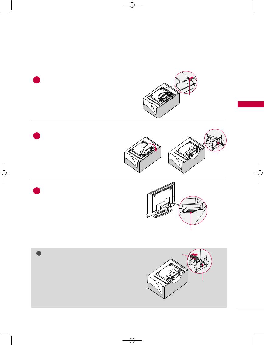
STAND INSTALLATION (FOR 42PC1D*)
1 |
screen facing |
|
cloth as |
||
|
||
|
shown. |
|
|
Before unfolding the stand, please make |
|
|
sure two locks (A) on the bottom of the |
|
|
stand push outward. |
2 Pull the stand out as shown.
After unfolding the stand, please insert and tighten the screws (provided as parts of the product) in the holes (B) on the bottom of the stand.
3 |
connecting cables to the set, Do |
|
the lock (C). |
||
|
||
|
This may cause the set to fall, causing |
|
|
serious bodily injury and serious damage |
! NOTE
Image shown here may be slightly different from your set.
G When closing the stand for storage
■ First remove the screws in the holes (B) on the bottom of the stand. And then pull two Hooks (D) of the stand bottom and fold the stand into the back of the set.
■After folding, push the two Locks (A) of the stand bottom outward.
(A)
INSTALLATION
(B)
(C)
(D)


 (A)
(A)
(B)
13
9U0569A-1 Rev05-ING 06/8/23 3:27 PM Page 14
INSTALLATION
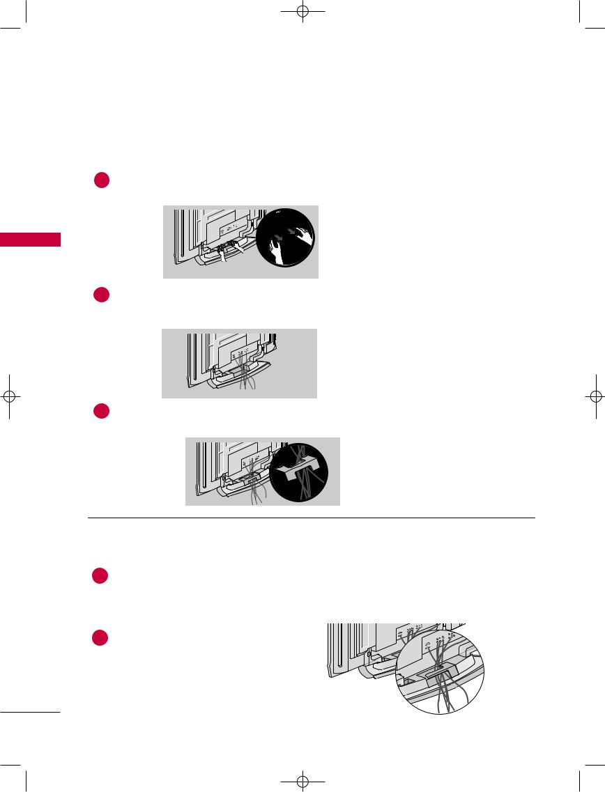
WIRE ARRANGEMENT
This function explains the features available on the 50PC1D*.
1 |
shown. |
|
INSTALLATION |
2 Connect the cables as necessary. |
|
|
|
To connect an additional equipment, see the Connections & Setup section. |
3
This function explains the features available on the 42PC1D*, 60PC1D*.
1
To connect an additional equipment, see the Connections & Setup section.
2
14
9U0569A-1 Rev05-ING 06/8/23 3:27 PM Page 15
This function explains the features available on the 32LC2D*, 37LC2D*, 42LC2D*.
1
To connect an additional equipment, see the Connections & Setup section.
37LC2D*, 42LC2D*
AC IN |
CABLE HOLDER
32LC2D*
AC IN |
CABLE HOLDER
2Install the CABLE MANAGEMENT as shown.
CABLE MANAGEMENT
AC IN |
3
AC IN |
How to remove the CABLE
MANAGEMENT
G Hold the CABLE MANAGEMENT with both hands and pull it upward.
! NOTE
G Do not hold the CABLE MANAGEMENT when moving the product.
-If the product is dropped, you may be injured or the product may be broken.
TWISTER HOLDER
INSTALLATION
15

9U0569A-1 Rev05-ING 06/8/23 3:27 PM Page 16
INSTALLATION
INSTALLATION
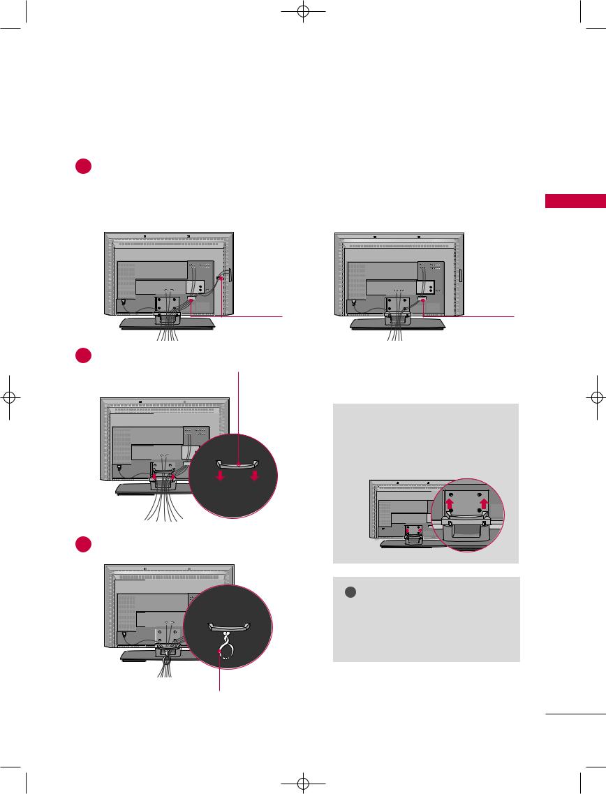
ATTACHING THE TV TO A WALL
Set it up close to the wall so the product doesn’t fall over when it is pushed backwards.
The instructions shown below is a safer way to set up the product, which is to fix it on the wall so the product doesn’t fall over when it is pulled in the forward direction. It will prevent the product from falling forward and hurting people. It will also prevent the product from damage caused by fall. Please make sure that children don’t climb on or hang from the product.
42/50/60PC1D* |
32/37/42LC2D* |
■Insert the eye-bolts (or TV brackets and bolts) to tighten the product to the wall as shown in the picture. * If your product has the bolts in the eye-bolts position before inserting the eye-bolts, loosen the bolts.
Insert the eye-bolts and tighten them securely in the upper holes.
Secure the wall brackets with the bolts (not provided as parts of the product, must purchase separately ) on the wall. Match the height of the bracket that is mounted on the wall to the holes in the product.
Ensure the eye-bolts or brackets are tightened securely.
■Use a sturdy rope (must be purchased separately) to secure the TV. It is safer to tie the rope so it runs horizontally between the wall and the TV.
16
9U0569A-1 Rev05-ING 06/8/23 3:27 PM Page 17
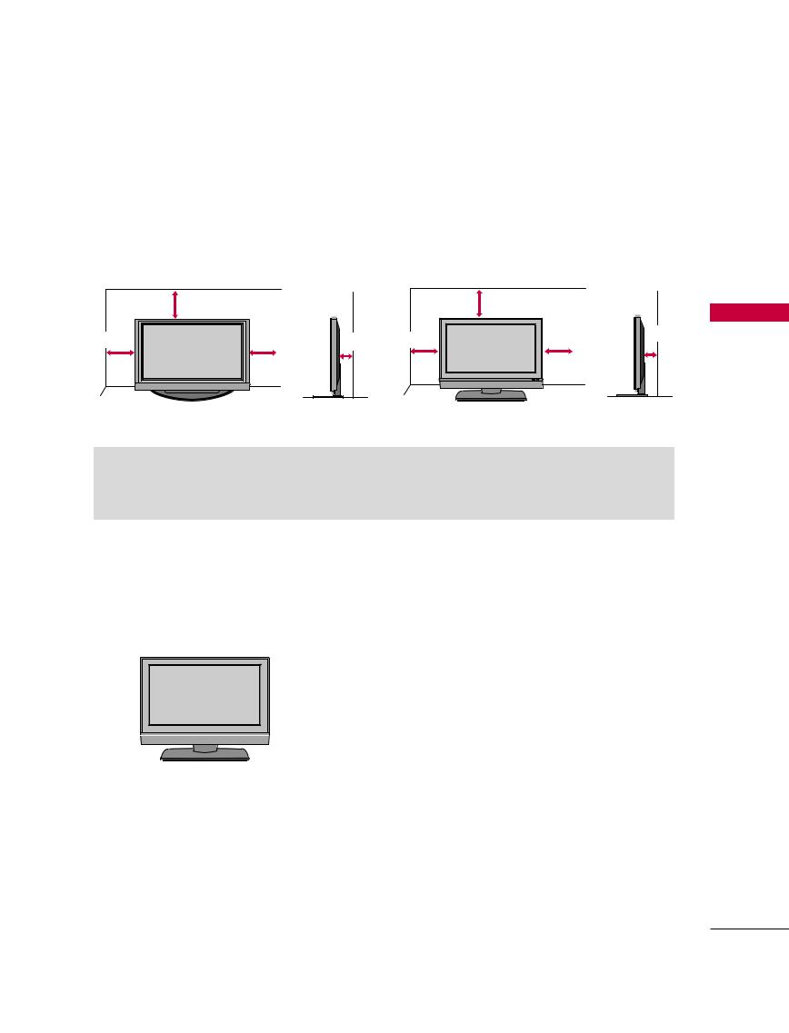
DESKTOP PEDESTAL INSTALLATION
For proper ventilation, allow a clearance of 4inches on each side from the wall.
42/50/60PC1D* |
|
32/37/42LC2D* |
|
|
4 inches |
|
4 inches |
|
|
4 inches |
4 inches |
4 inches 4 inches |
4 inches |
4 inches |
|
 CAUTION
G Ensure adequate ventilation by following the clearance recommendations.
INSTALLATION
SWIVEL STAND
This function explains the features available on the 42LC2D*.
30° |
30° |
The TV can be conveniently swivelled on its stand 30° to the left or right to provide the optimum viewing angle.
17
9U0569A-1 Rev05-ING 06/8/23 3:27 PM Page 18
CONNECTIONS & SETUP
‘Connections & Setup’ part explains the features available on the 32/37/42LC2D*.
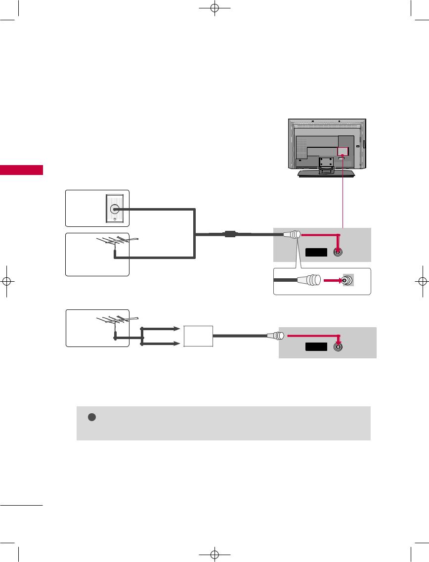
ANTENNA CONNECTION
Wall Antenna Socket or Outdoor Antenna without a Cable Box Connections. For optimum picture quality, adjust antenna direction if needed.
AC IN |
SETUP & CONNECTIONS
Multi-family Dwellings/Apartments
Wall  (Connect to wall antenna socket)
Antenna
Socket
Outdoor |
RF Coaxial Wire (75 ohm) |
Antenna |
|
(VHF, UHF) |
|
|
Single-family Dwellings /Houses |
|
(Connect to wall jack for outdoor antenna) |
|
UHF |
|
Antenna |
VHF |
Signal |
|
Amplifier |
|
|
|
ANTENNA
IN
■To improve the picture quality in a poor signal area, please purchase a signal amplifier and install properly.
■If the antenna needs to be split for two TV’s, install a 2-Way Signal Splitter.
■If the antenna is not installed properly, contact your dealer for assistance.
! NOTE
G The TV will let you know when the analogue, cable, and digital programme scans are complete.
18
9U0569A-1 Rev05-ING 06/8/23 3:27 PM Page 19
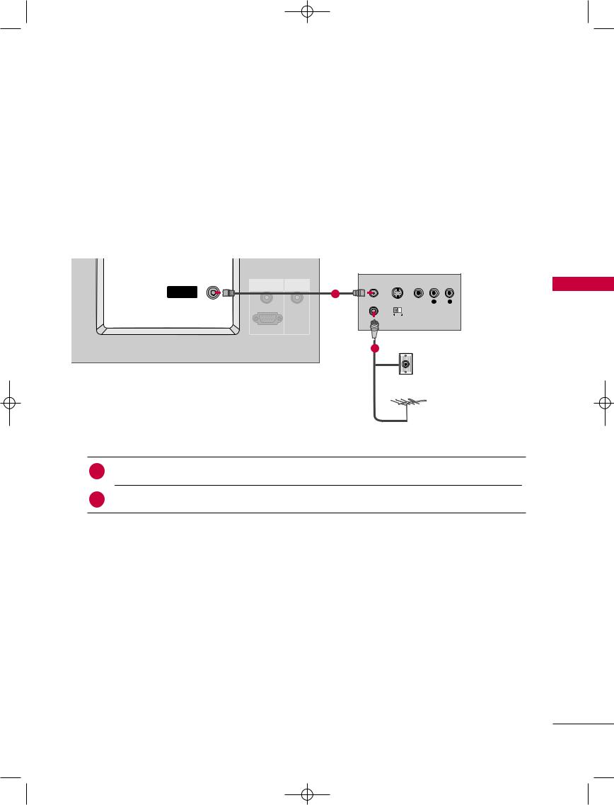
ANTENNA LOOP THROUGH SOCKET
- 42PC1DV, 32/37/42LC2D only
The TV has a special signal output capability which allows you to hook up the second TV.
|
(MONO) |
|
|
|
|
|
|
|
|
VIDEO |
AUDIO |
S-VIDEO |
VIDEO |
AUDIO |
|
|
|
|
|
|
AV IN 1 |
|
COMPONENT IN |
|
|
|
|
|
|
|
|
ANTENNA |
|
|
ANT OUT |
S-VIDEO |
VIDEO |
L |
R |
|
|
|
|
2 |
|
|
|
|
|
|
|
OUT |
|
|
|
|
|
|
|
|
|
|
|
|
|
|
|
|
|
|
|
|
|
|
ANT IN |
OUTPUT |
|
|
|
|
|
|
|
|
|
SWITCH |
|
|
|
|
|
|
|
RGB IN |
REMOTE |
|
|
|
|
|
|
|
|
CONTROL IN |
|
|
|
|
|
|
|
|
|
|
|
|
|
|
|
|
|
|
|
|
|
|
Wall Jack |
|
|
|
|
|
|
AUDIO (RGB/DVI) |
|
|
|
|
|
|
|
|
|
RGB (PC/DTV) |
|
|
|
|
|
|
|
|
|
|
|
|
Antenna |
|
|
1. How to connect
1 Connect the wall antenna socket or outdoor antenna to the TV’s |
TENNA IN socket. |
TV’s antenna socket to the TV’s ANTENNA OUT socket.
! NOTE
G In standby mode, these ports do not work.
SETUP & CONNECTIONS
19
9U0569A-1 Rev05-ING 06/8/23 3:28 PM Page 20
CONNECTIONS & SETUP
SETUP & CONNECTIONS
HDSTB SETUP
This TV can receive Digital Over-the-air/Cable signals without an external digital set-top box. However, if you do receive digital signals from a digital set-top box or other digital external device, refer to the figure as shown below.
This TV supports HDCP (High-bandwidth Digital Contents Protection) protocol for Digital Contents (480p,720p,1080i).
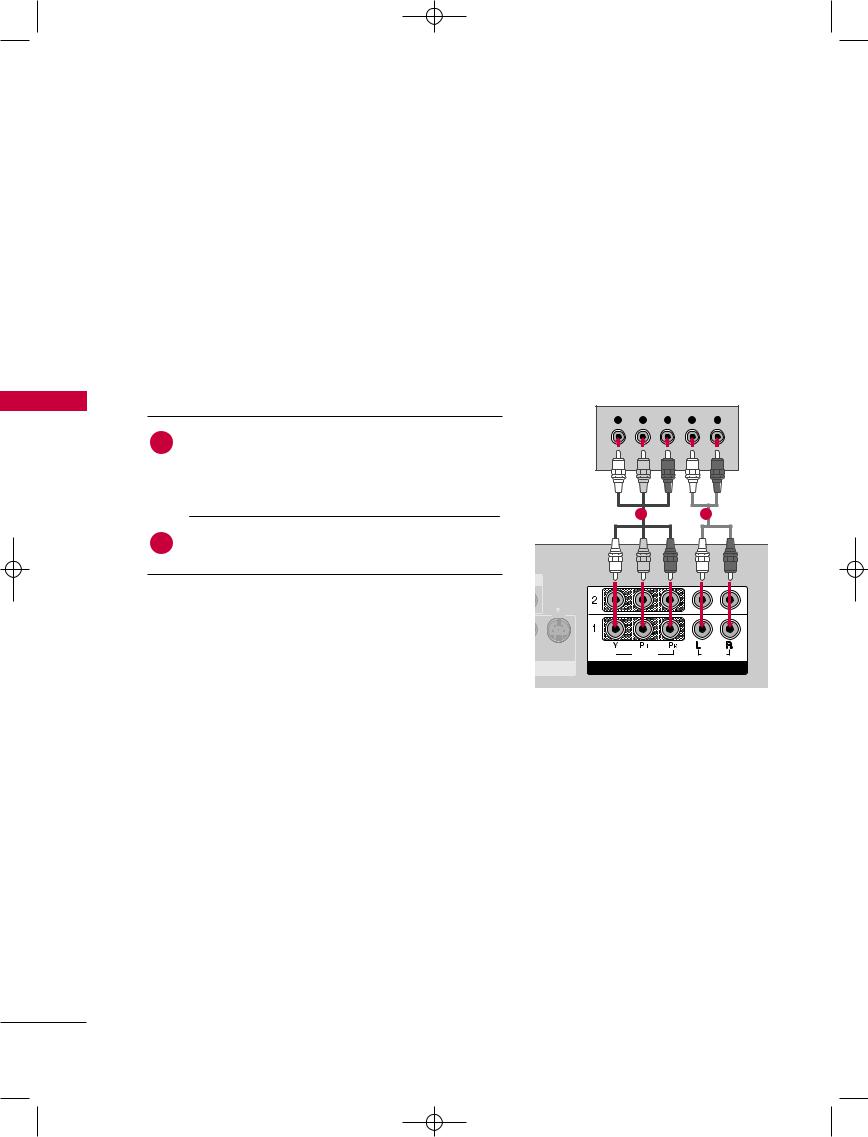
When connecting Component cable
1. How to connect
Y PB PR L R
1
Connect the video outputs (Y, PB, PR) of the digital set top box to the COMPONENT IN VIDEO 1 jacks on the set. Match the jack colors
(Y = green, PB = blue, and PR = red)
1 |
2 |
box to
2. How to use
■ Turn on the digital set-top box. |
|
|
|
(Refer to the owner’s manu-al for the digital set-top box.) |
S-VIDEO |
O |
AUDIO |
|
|
PONENT IN |
|
■Select Component 1 input source with using the INPUT button on the remote control.
■If connected to COMPONENT IN 2 input, select Component 2 input source.
Signal |
Component 1/2 |
RGB-DTV, HDMI |
|
|
|
|
Yes |
No |
480i |
||
480p |
Yes |
Yes |
576i |
Yes |
No |
576p |
Yes |
Yes |
720p |
Yes |
Yes |
1080i |
Yes |
Yes |
|
|
|
20
9U0569A-1 Rev05-ING 06/8/23 3:28 PM Page 21
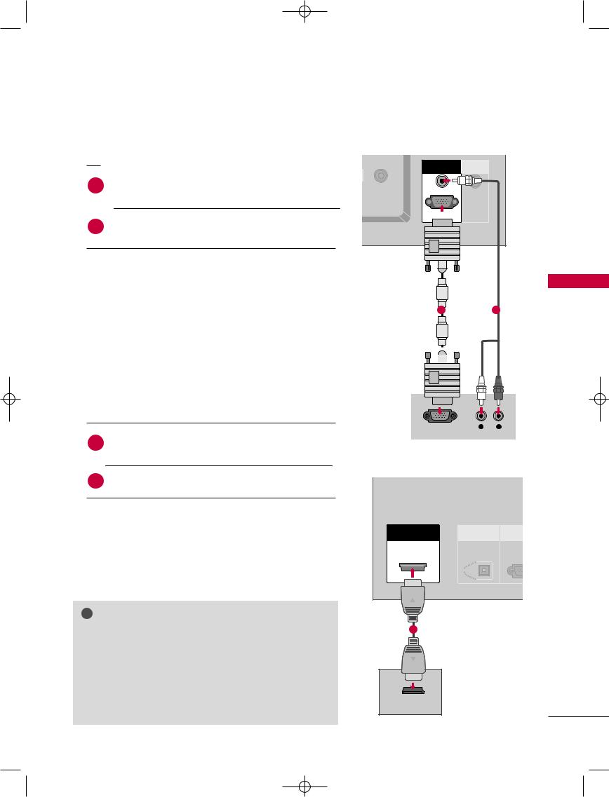
When connecting D-sub 15pin cable
1. How to connect
1 |
Connect the RGB output of the digital |
|
RGB (PC/DTV) jack on the set. |
||
|
||
|
outputs of the |
|
|
on the set. |
|
RGB IN |
REMOTE |
|
ANTENNA |
CONTROL IN |
||
|
|||
|
|
||
IN |
|
|
|
|
AUDIO (RGB/DVI) |
|
|
|
RGB (PC/DTV) |
|
2.to use
on the digital set-top box.
|
|
to the owner’s manual for the digital set-top box.) |
|
|
|
&CONNECTIONS |
|
|
|
|
|
1 |
|
2 |
|
|
|
|
|
|
|
||
|
|
input source with using the |
|
|
|
|
|
|
|
on the remote control. |
|
|
|
|
|
When connecting HDMI cable |
|
|
|
|
SETUP |
||
1. |
|
to connect |
|
|
|
|
|
|
|
|
|
RGB OUTPUT |
L |
R |
|
|
1 |
Connect the digital set-top box to HDMI/DVI |
IN |
|
|
|
|
|
jack on the set. |
|
|
|
|
|
|
|
|
|
|
|
|
|
|
|
|
No separated audio connection is necessary. |
|
|
|
|
|
2. |
|
to use |
|
|
DIGITAL AUDIO |
RS-2 |
|
|
|
|
HDM |
I IN |
|||
|
|
on the digital set-top box. |
OUT |
|
(CONTRO |
||
|
|
|
|
|
|||
|
|
to the owner’s manual for the digital set-top box.) |
|
|
OPTICAL |
|
|
|
|
HDMI/DVI input source with using the INPUT |
|
|
|
|
|
|
|
on the remote control. |
|
|
|
|
|
! |
NOTE |
|
|
|
|
|
|
G If the digital set-top box supports Auto HDMI function, the |
1 |
|
|
|
|||
|
|
|
|
||||
|
output resolution of the source device will be automatically |
|
|
|
|
||
|
set to 1280x720p. |
|
|
|
|
|
|
G If the digital set-top box player does not support Auto HDMI, you need to set the output resolution appropriately. To get the best picture quality, adjust the output resolution of the source device to 1280x720p.
HDMI-DTV OUTPUT
21
9U0569A-1 Rev05-ING 06/8/23 3:28 PM Page 22
CONNECTIONS & SETUP
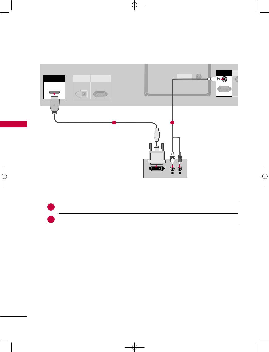
When connecting HDMI to DVI cable
|
|
|
OUT |
|
|
|
|
|
|
RGB IN |
REM |
|
|
|
ANTENNA |
CONT |
|
|
DIGITAL AUDIO |
RS-232C IN |
|
||
HDMI/DVI IN |
|
|
|||
IN |
|
|
|||
OUT |
(CONTROL&SERVICE) |
|
|
||
|
|
|
|
||
|
OPTICAL |
|
|
AUDIO (RGB/DVI) |
|
|
|
|
|
|
|
|
|
|
|
RGB (PC/DTV) |
|
SETUP & CONNECTIONS
1 |
2 |
DVI-DTV OUTPUT |
L |
R |
1. How to connect
1 Connect the DVI output of |
digital set-top box to the HDMI /DVI IN jack on the set. |
the audio output of the digital set-top box to the AUDIO(RGB/DVI) jack on the set.
2.How to use
■Turn on the digital set-top box. (Refer to the owner’s manual for the digital set-top box.)
■Select HDMI/DVI input source with using the INPUT button on the remote control.
22
9U0569A-1 Rev05-ING 06/8/23 3:28 PM Page 23
VCR SETUP
■To avoid picture noise (interference), leave an adequate distance between the VCR and TV.
■If the 4:3 picture format is used; the fixed images on the sides of the screen may remain visible on the screen. This phenomenon is common to all manufactures and in consequence the manufactures warranty does not cover the product bearing this phenomenon.
When |
antenna |
||
ANTENNA |
|
|
|
OUT |
|
|
|
|
RGB IN |
REMOTE |
|
ANTENNA |
CONTROL IN |
||
|
|||
|
|
||
IN |
|
1 |
|
|
AUDIO (RGB/DVI) |
S-VIDEO VIDEO L R |
|
|
|
||
|
|
OUTPUT |
|
|
RGB (PC/DTV) |
SWITCH |
|
|
|
||
Wall Jack
2
Antenna
1. How to connect
1 Connect the RF antenna out socket of the VCR to the Antenna socket on the set.
the antenna cable to the RF antenna in socket of the VCR.
2.How to use
■Set VCR output switch to 3 or 4 and then tune TV to the same programme number.
■Insert a video tape into the VCR and press PLAY on the VCR. (Refer to the VCR owner’s manual.)
SETUP & CONNECTIONS
23
9U0569A-1 Rev05-ING 06/8/23 3:28 PM Page 24
CONNECTIONS & SETUP
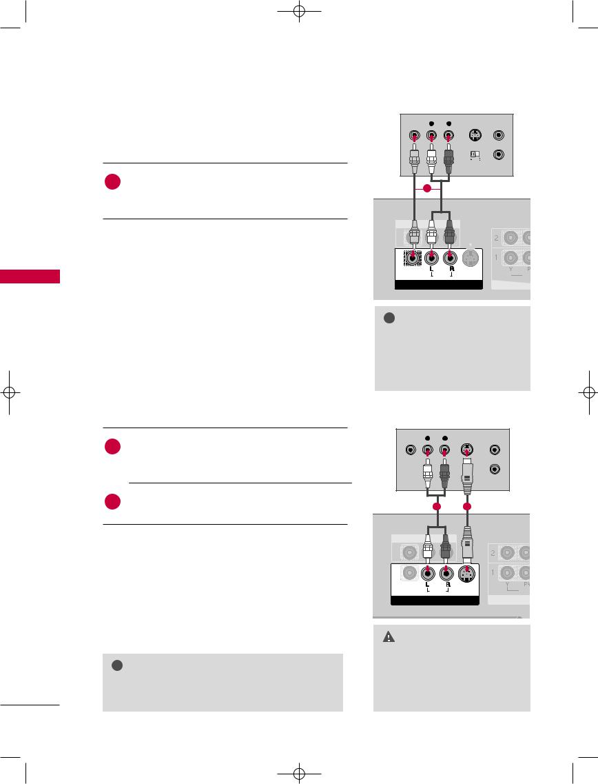
SETUP & CONNECTIONS
When connecting with a RCA cable |
VIDEO L R S-VIDEO ANT IN |
||
1. How to connect |
|
||
|
|
|
OUTPUT ANT OUT |
|
|
|
SWITCH |
|
1 |
the AUDIO/VIDEO jacks between TV and |
|
|
the jack colors(Video = yellow, Audio Left = |
1 |
|
|
|
||
|
|
white, and Audio Right = red) |
|
2. |
|
to use |
|
a video tape into the VCR and press PLAY on the
. (Refer to the VCR owner’s manual.)
AV1 input source with using the INPUT button on remote control.
connected to AV IN2, select AV2 input source.
When connecting with an S-Video cable
(MONO) |
|
|
VIDEO AUDIO |
VIDEO |
VID |
V IN 1 |
|
CO |
! NOTE
|
ANT |
NA |
G If you have a |
O |
VCR, con- |
|
||
nect the audio cable from the |
||
VCR to the AU |
|
|
L(MONO) jackANT |
NAthe set. |
|
1.to connect
Connect the S-VIDEO output of the VCR to the S-VIDEO |
VIDEO L R |
S |
ANT IN |
|
1 |
|
input on the set. The picture quality is improved; com |
|
pared to normal composite (RCA cable) input. |
|
|
ANT OUT |
Connect the audio outputs of the VCR to the AUDIO |
|
input jacks on the set. |
2 |
|
|
AV |
|
|
2. |
to use |
|
|
|
a video tape into the VCR and press PLAY on the VCR. |
|
|
|
to the VCR owner’s manual.) |
(MONO) |
VID |
|
VIDEO |
AUDIO S-VIDEO |
|
|
|
AV IN 1 |
CO |
AV1 input source with using the INPUT button on the control.
ANTENNA
OUT
! NOTE
G The picture quality is improved: ; compared to normal
the event that you connect both
composite (RCA cable) input.
Video and the S-Video cables, only the S-Video will work.
24
9U0569A-1 Rev05-ING 06/8/23 3:28 PM Page 25
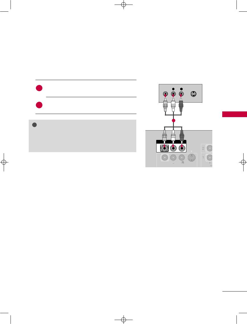
AV OUT SETUP
The TV has a special signal output capability which allows you to hook up the second TV or monitor.
1. How to connect
1
Connect the second TV or monitor to the
TV’s AV OUT jacks.
the Operating Manual of the second TV or monitor further details regarding that device’s input settings.
!
G Digital, Component1-2, RGB-PC/RGB-DTV, HDMI/DVI input sources cannot be used for AV out.
G We recommend to use the AV OUT jacks for VCR recording.
VIDEO |
L |
R |
S-VIDEO |
1
V
 (MONO)
VIDEO  AUDIO
AUDIO  S-VIDEO
SETUP & CONNECTIONS
25
9U0569A-1 Rev05-ING 06/8/23 3:28 PM Page 26
CONNECTIONS & SETUP
SETUP & CONNECTIONS
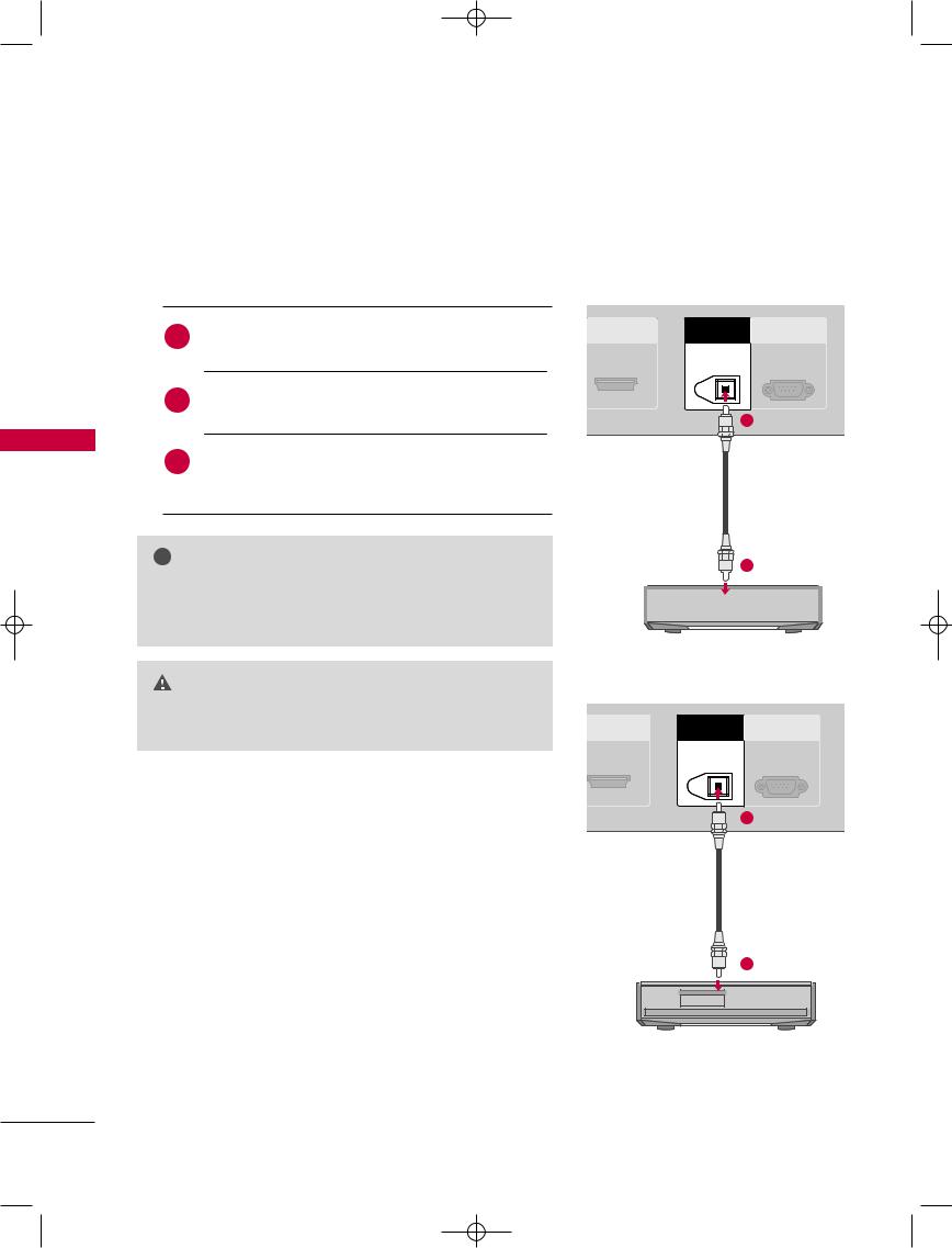
DIGITAL AUDIO OUTPUT
Send the TV’s audio to external audio equipment via the Digital Audio Output (Optical) port.
1. How to connect
Connect one end of an optical cable to the TV Digital
1Audio (Optical) Output port.
Set the “TV Speaker option - Off” in the AUDIO menu. (G p.68). See the external audio equipment instruction manual for operation.
i.e) 32/37/42LC2D*
HDMI/DVI IN |
DIGITAL AUDIO |
RS-232C IN |
|
OUT |
(CONTROL&SERVICE) |
||
|
OPTICAL
1
!
Gconnecting with external audio equipments, such amplifers or speakers, please turn the TV speakers (G p.68)
GDo not look into the optical output port. Looking at the laser beam may damage your vision.
2
i.e)42PC1D*, 50PC1D*, 60PC1D*
DMI/DVI IN |
DIGITAL AUDIO OU |
RS-232C IN |
|
OPTICAL |
(CONTROL&SERVICE) |
||
|
1
2
26
9U0569A-1 Rev05-ING 06/8/23 3:28 PM Page 27
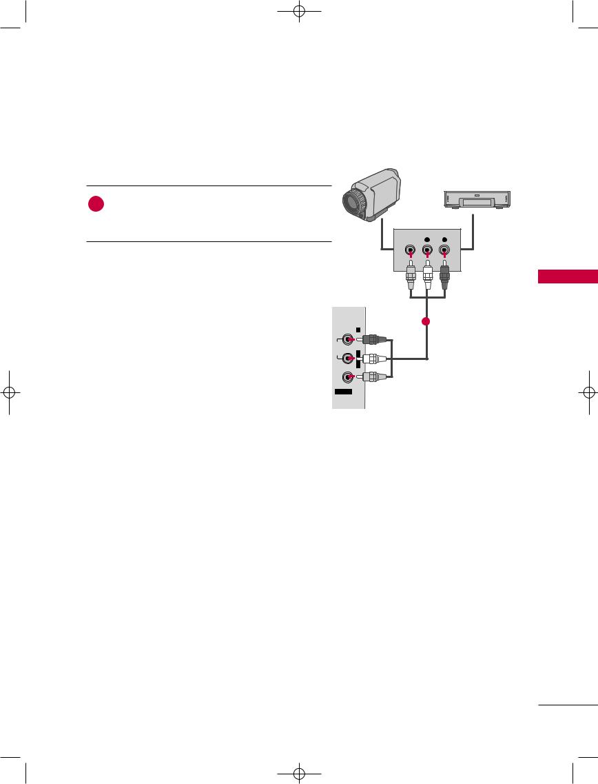
EXTERNAL A/V SOURCE SETUP
Camcorder
1. How to connect |
Video Game Set |
1
TV and
Video = yellow,
Audio Left = white, and Audio Right = red)
VIDEO |
R |
2. How to use
AV1 input source with using the INPUT button on remote control.
1
|
R |
the corresponding external equipment. |
|
AUDIO |
L/MONO |
VIDEO |
|
AV IN 2 |
|
i.e) 37/42LC2D*
SETUP & CONNECTIONS
27
9U0569A-1 Rev05-ING 06/8/23 3:28 PM Page 28
CONNECTIONS & SETUP
SETUP & CONNECTIONS
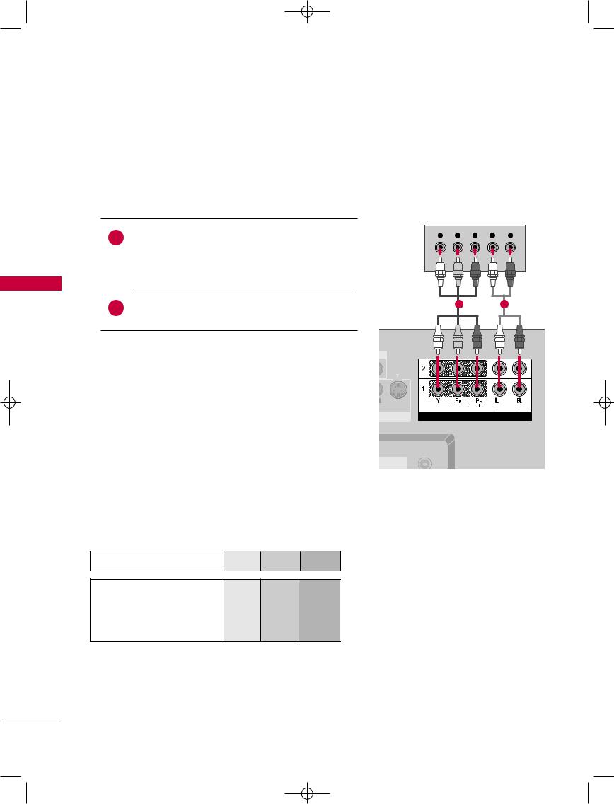
DVD SETUP
When connecting Component cable
1. How to connect
1 |
Connect the video outputs (Y, PB, PR) of the DVD to the |
Y PB PR L R |
COMPONENT IN VIDEO1 jacks on the set. |
|
|
|
|
|
|
Match the jack colors (Y = green, PB = blue, and PR = red). |
|
1 |
2 |
ENT IN AUDIO1 jacks on the set.
2. How to use
on the DVD player, insert a DVD.
Component 1 input source with using the INPUT on the remote control.
connected to COMPONENT IN 2 input, select mponent 2 input source.
to the DVD player's manual for operating instruc-
.
S-VIDEO |
VIDEO |
AUDIO |
COMPONENT IN
ANTENNA
OUT
Component Input ports
To get better picture quality, connect a DVD player to the component input ports as shown below.
Component ports on the TV |
Y |
PB |
PR |
Video output ports on DVD player
Y |
Pb |
Pr |
Y |
B-Y |
R-Y |
Y |
Cb |
Cr |
Y |
Pb |
Pr |
28
 Loading...