


VM9312HD
VM9312HD
Installation and Operation Manual
Multimedia Receiver
SAT
READY
PRESS AUDIO
VM9312HD
160
Watts P eak
40W x 4


CONTENTS
Thank you for choosing a Jensen product. We hope you will find the instructions in this owner’s
manual clear and easy to follow. If you take a few minutes to look through it, you’ll learn how to
use all the features of your new Jensen VM9312HD Mobile Multimedia Receiver for maximum
enjoyment.
Preparation............................................................................................................................ 1
Installation............................................................................................................................. 2
Controls and Indicators......................................................................................................... 6
Remote Control..................................................................................................................... 8
Using the TFT Monitor ........................................................................................................ 11
Operating Instructions......................................................................................................... 12
Setup Menu......................................................................................................................... 13
Tuner Operation.................................................................................................................. 15
Satellite Radio Operation.................................................................................................... 17
DVD/VCD Video Operation................................ ................................................................. 19
DVD/CD Audio Operation ................................................................................................... 22
MP3/WMA Operation.......................................................................................................... 23
iPod Operation.................................................................................................................... 25
Troubleshooting .................................................................................................................. 26
Specifications...................................................................................................................... 29
VM9312HD
i

VM9312HD
ii
PREPARATION
Congratulations on your purchase of the Jensen VM9312HD
Mobile Multimedia Receiver.
It’s a good idea to read all of the instructions before beginning
the installation. We recommend having your Jensen
VM9312HD installed by a reputable installation shop.
Features
DVD
• Aspect Ratio - Full and Normal
• Fast Forward - 2X, 4X, 8X and 32X
• Slow Motion - 1/2, 1/4, 1/6 and 1/7
• Play, Pause, Stop, Next Chapter and Previous Chapter
CD / MP3 / WMA
• CD-Text Compatible
• ID3 Tag Compatible
• Directory Search (MP3 / WMA Only)
• Direct Track Access via Remote Control
• Burn up to 1500 MP3 and WMA Files onto a DVD+R /
RW
• Audible Forward / Reverse Track Search (CD-DA Only)
• Random, Repeat and Intro
• Play, Pause, Stop, Next Track and Previous Track
Tuner
• HD Radio Tuner*
• USA / Europe Frequency Spacing
• 24 Station Presets (18 FM / 6 AM)
• Auto Stereo / Mono
• Auto Store
• RDS - Radio Data System
Sat Radio Ready
• Compatible with XM and Sirius Tuners (Sold Sep arately)
• Requires XMDJEN100 or JXMC cables for XMD1000
only (Sold Separately)
• Satellite Channel Name, Artist, Song and Categories
displayed on TFT Screen
iPod
• jLinkDirect - High Speed Direct Connect Interface to
Access iPod Playlists, Artists, Albums, Songs, Photos**
and Video**. (Requires Gen 5.5 or earlier photo or video
iPod. iPod Touch, iPod Classic and iPod Nano with
video will only play music files.
• Power Management Charges iPod while Connected
• Requires jLinkCable iPod Interface Cable (included)
MediaLink
• Under dash Interface allows Portable Media Devices to
be connected
• MediaLink1 includes the following connectivity:
• jLinkDirect 8-pin DIN for iPod
• 3.5mm audio only Input
• RCA Audio / Video Input
Chassis
• 1.0 DIN (Import / ISO-DIN Mountable)
• Motorized Flip-Out / Flip-Up LCD Screen
• 8 Character / Segment Type Secondary LCD Display
• 7" TFT Active Matrix LCD w/ Anti-Glare Coating
• 336,960 Sub Pixels (1440W X 234H)
• Pixel Pitch – 0.321W X 0.370H
• Screen Tilt / Angle Adjustment
• Beep Tone Confirmation (On-OFF Option)
• Heat Management System – Forced Air Cooling to keep
the chip sets operating at nominal temperatures
General
• 44-Key Infrared Remote Control
• Two Composite Video Outputs for Additional Screens
• Two Audio / Video Auxiliary Inputs for Game Console,
Camcorder, etc.
• Navigation Ready (Nav101 Only)
• Three-Band Tone control (Bass, Mid and Treble) w/
Eight Preset EQ Curves
• Front, Rear and Subwoofer Line Output
• Subwoofer Phase Control – 0 ~ 180 degrees
• Programmable Volume Control
• Rear Camera Input (Normal and Mirror Image View)
• Touch Screen Calibration Mode
• 100-Ohm Preamp Line Output – All Audio Channels
• 2VRMS Line Output – All Channels
• Rotary Encoder Audio Control
• 5-Way Joystick
• SWC Interface – Compatible with PAC adapter SWI-PS
Steering Wheel Control Interface, sold separately
*HD Radio™ Technology Manufactured Under License From
iBiquity Digital Corporation. U.S. and Foreign Patents. The
HD and HD Radio logos are proprietary trademarks of
iBiquity Digital Corporation.
VM9312HD
WARNING! Only connect the unit to a12-volt power
supply with proper grounding.
WARNING! Never install this unit where operation and
viewing could interfere with safe driving conditions.
WARNING! To reduce the risk of a traffic accident (except
when using for rear view video camera) never use the
video display function while driving the vehicle. This is a
violation of federal law.
WARNING! Never disassemble or adjust the unit.
WARNING! To prevent injury from shock or fire, never
expose this unit to moisture or water.
WARNING! Never use irregular discs.
WARNING! To prevent damage to the mechanism inside
this unit, avoid impact to the TFT monitor.
WARNING! Using an improper fuse may cause damage
to the unit and result in a fire.
WARNING! The monitor employs an automatic motorized
mechanism. To prevent damage to the core mechanism,
please do not push, pull or swivel the monitor manually.
1
VM9312HD
INSTALLATION
What’s in the Box
1. Cosmetic trim ring
2. Wiring harness power/speaker
3. Mounting hardware for VM9312HD
4. Single DIN sleeve
5. HD Radio Module
6. HD Radio Module connecting DIN cable
7. Remote Control
8. Parking brake sensor extension wire
9. Media Link Module
10. Mounting hardware for HD Radio Module
11. Owners Manual
12. Quick Start Guide
Optional Equipment
• NAV101
The VM9312HD is "navigation ready." Before accessing
any navigation features, you must purchase and install
the NAV101 module. All installation and operating
instructions will be included with the NAV101 navigation
module.
Once the NAV101 is connected and operating properly,
the NAV source mode will become active. While the
NAV101 is not installed, the NAV option appears gray,
indicating the function is not available.
• Rear Camera
The VM9312HD is "camera ready." Before accessing
any camera features, you must purchase and install a
rear video camera. Once the rear camera is connected
and operating properly, the CAMERA source mode will
become active. While the camera is not installed, the
CAMERA option appears gray, indicating the function is
not available.
• Satellite Radio Tuner
See “Satellite Radio Operation” on page 17.
• iPod
See “MP3/WMA Operation” on page 23.
Tools and Supplies
You will need these tools and supplies to install your
VM9312HD:
• Torx type, flat-head and Philips screwdrivers
• Wire cutters and strippers
• Tools to remove existing radio (screwdriver, socket
wrench set or other tools)
• Electrical tape
• Crimping tool
• Volt meter/test light
• Crimp connections
• 18 gauge wire for power connections
• 16 – 18 gauge speaker wire
Disconnecting the Battery
To prevent a short circuit, be sure to turn off the ignition and
remove the negative (-) battery cable prior to installation.
NOTE: If the VM9312HD is to be installed in a car
equipped with an on-board drive or navigation computer,
do not disconnect the battery cable. If the cable is
disconnected, the computer memory may be lost. Under
these conditions, use extra caution during installation to
avoid causing a short circuit.
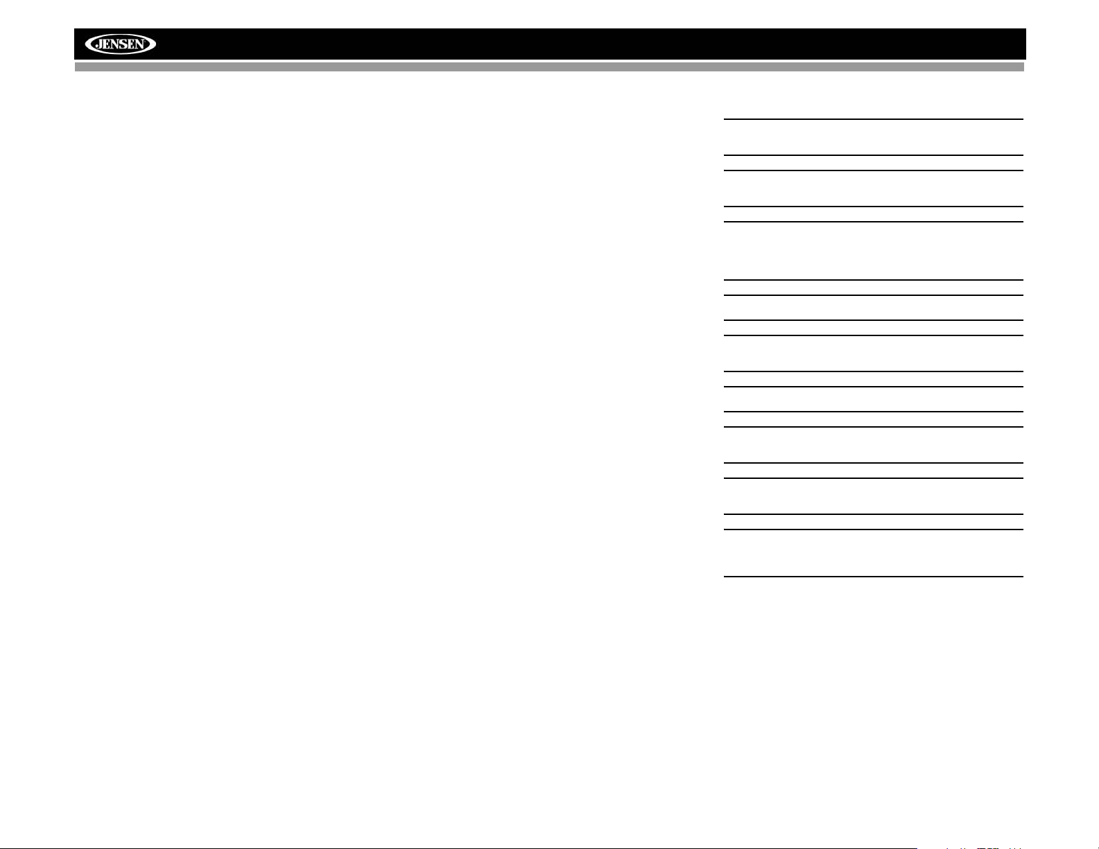
Pre-installation
1. Press the metal levers on both sides to remove the halfsleeve from the radio.
PREPARE RADIO
BAND
AS/PS
PRESSAUDIO
LO/DX
VM9312
SRC
2. Install the half-sleeve.
a. Install adapter if necessary (optional).
DISP
OPEN
EJECT
MUTE
b. Install half-sleeve into adapter or dashboard (use
only the supplied screws). Do not force the sleeve
into the opening or cause it to bend or bow.
c. Locate the series of bend-tabs along the top,
bottom and sides of the mounting sleeve. With the
sleeve fully inserted into the dashboard opening,
bend as many of the tabs outward as necessary so
that the sleeve is firmly secured to the dashboard.
d. Install support strap to make the unit more stable.
INSTALL HALF SLEEVE
CAUTION! Be careful not to damage the car wiring.
3. Place the radio in front of the dashboard opening so the
wiring can be brought through the mounting sleeve.
Wiring
Complete wiring as illustrated in the wiring diagram on page
3. Once the wiring is complete, reconnect the battery
negative terminal. If there is no ACC available, connect the
ACC lead to the power supply with a switch.
NOTE: When replacing a fuse, be sure to use correct
type and amperage to avoid damaging the radio. The
VM9312HD uses one 15 amp mini-ATM fuse, located in
the black filter box in-line with the main wire harness.
2
VM9312HD
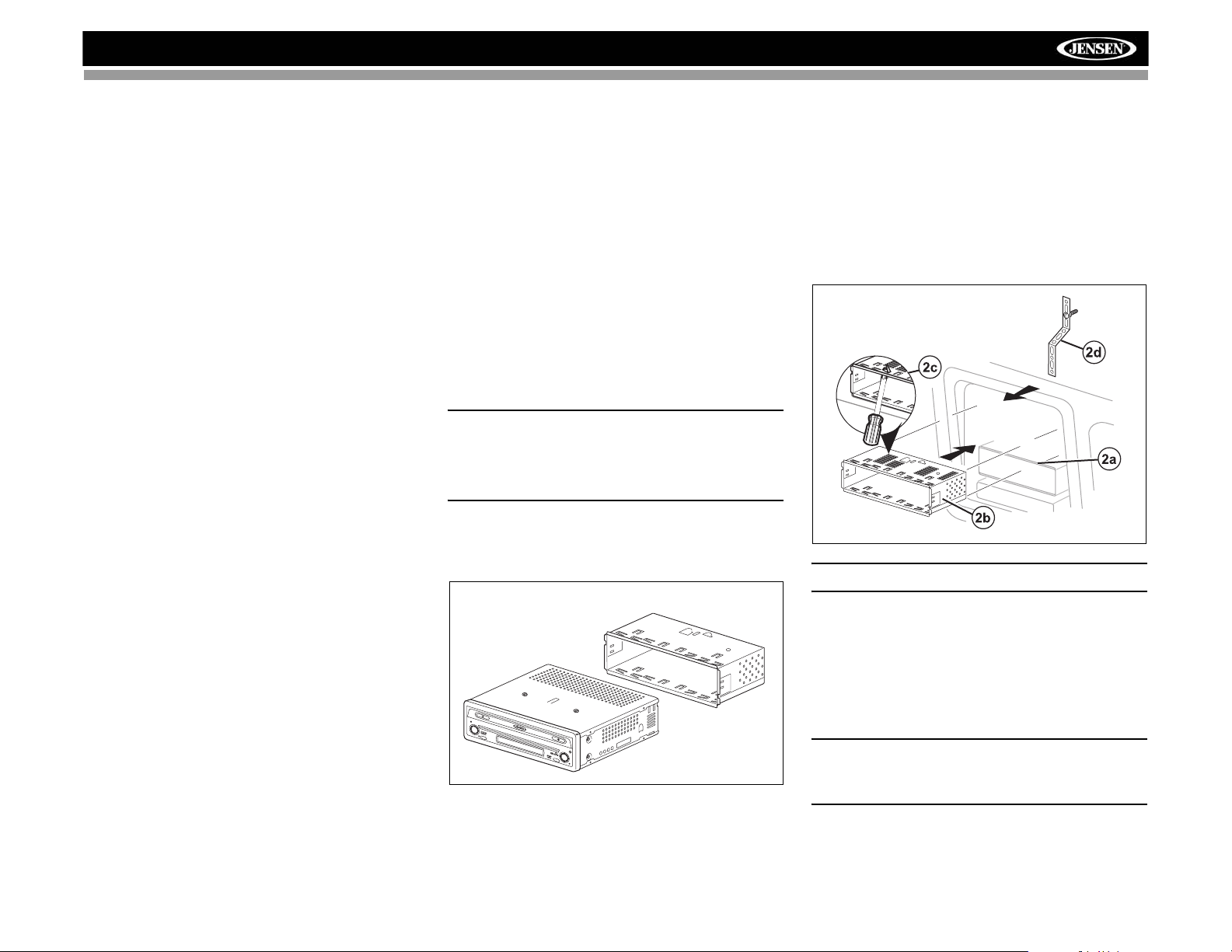
Final Installation
After completing the wiring connections, turn the unit on to
confirm operation (ignition switch must be on). If unit does not
operate, recheck all wiring until problem is corrected. Once
proper operation is achieved, turn off the ignition switch and
proceed with final mounting of the chassis.
1. Connect wiring adapter to existing wiring harness.
2. Connect antenna lead.
3. Carefully slide the radio into the half-sleeve, making
sure it is right-side-up, until it is fully seated and the
spring clips lock it into place.
NOTE: For proper operation of the CD/DVD player, the
chassis must be mounted within 20° of horizontal. Make
sure the unit is mounted within this limitation.
4. Attach one end of the perforated support strap
(supplied) to the screw stud on the rear of the chassis
using the hex nut provided. Fasten the other end of the
perforated strap to a secure part of the dashboard either
above or below the radio using the screw and hex nut
provided. Bend the strap to position it as necessary.
CAUTION! The rear of the radio must be supported with
the strap to prevent damage to the dashboard from the
weight of the radio or improper operation due to
vibration.
5. Replace any items you removed from the dashboard.
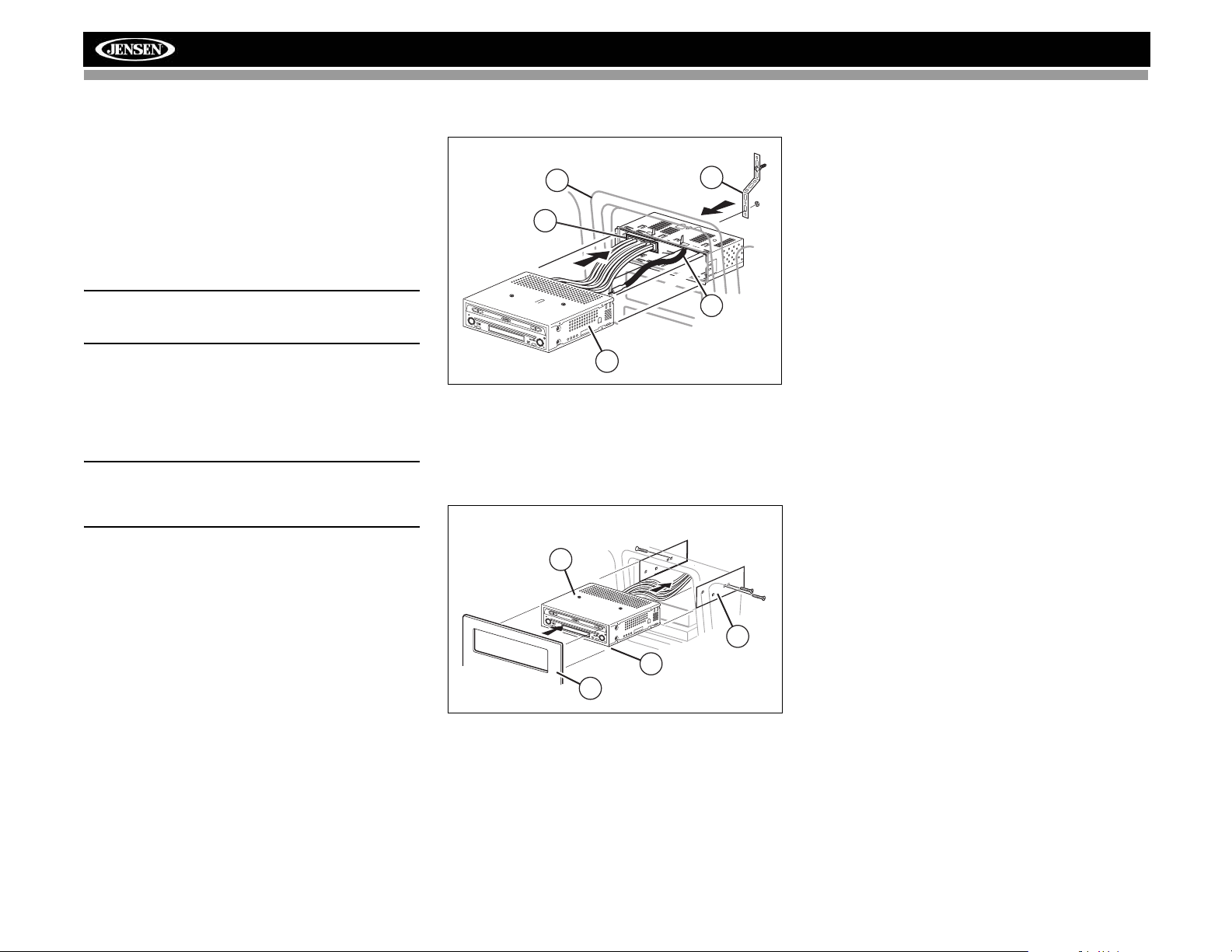
Final ISO-DIN Installation
FINAL INSTALLATION
5
1
BAND
AS/PS
PRESS
AU
D
IO
LO/DX
VM9312
SRC
DISP
OPEN
EJECT
MUTE
3
1. Remove trim ring.
2. Mount factory brackets on new radio using existing
screws from old radio.
3. Slide radio chassis into dash opening and secure.
4. Reinstall dash panel.
FINAL ISO-DIN INSTALLATION
3
4
2
BAND
AS/PS
PRESS
AUDIO
LO
/D
X
VM9312
SRC
DISP
OPEN
EJEC
T
MUTE
2
1
4
3
VM9312HD
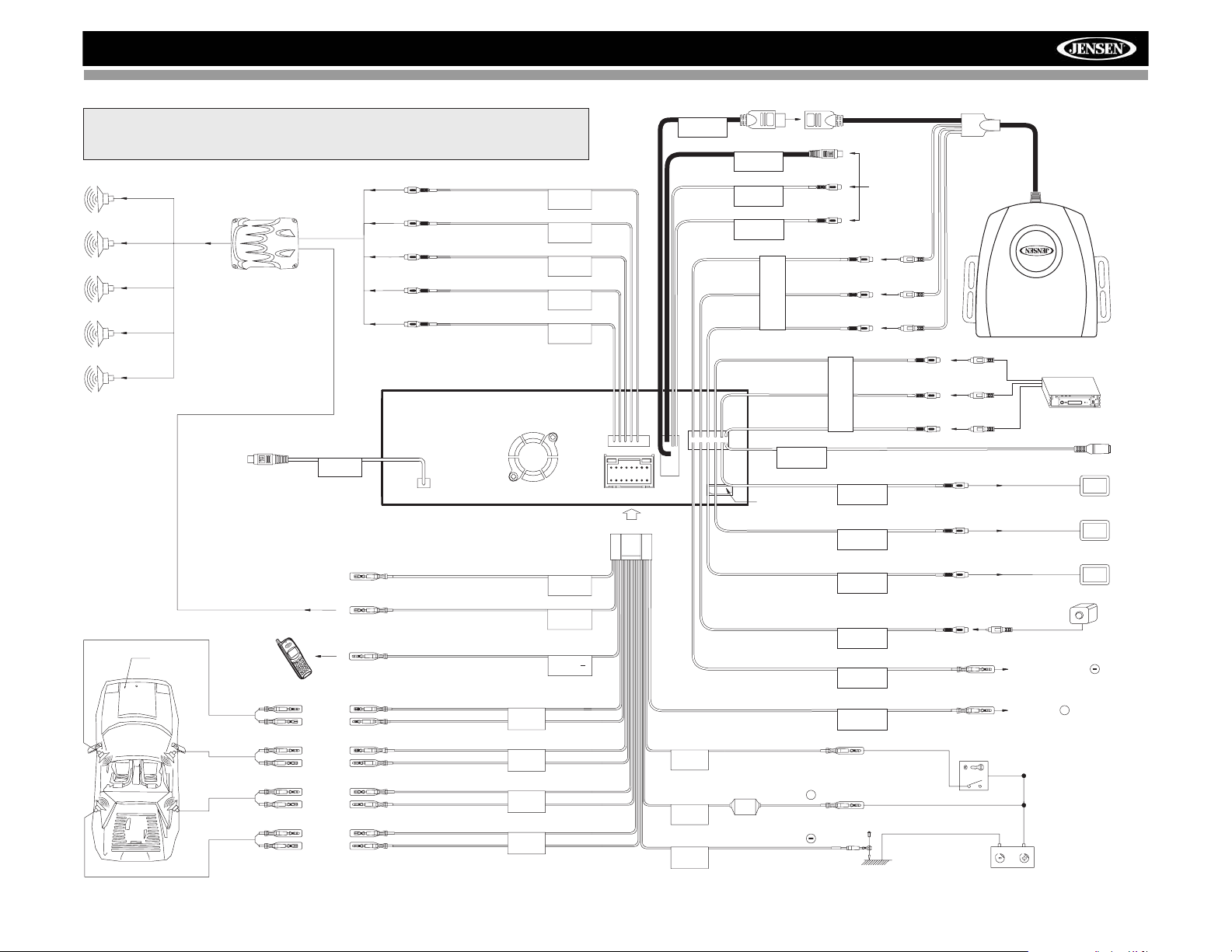
WIRING DIAGRAM
See the Module Connections diagram for more information about
*
connecting a satellite receiver and an iPod (through the MediaLink).
BLUE
External Power Amplifier
RED
WHITE
RED
WHITE
Connect to HD Module
(See Module
Connections Diagram)
HD RADIO
Auto antenna control (connectto antenna
control lead & powersupply of antenna
amplifier)
External power amplifier control
Car Phone
Car
Mute (leave open ifnot connected)
SUB.W
FRONTR
FRONTL
REAR R
REAR L
BLUE
ANT.CONT
BLUE/WHITE
P.CONT
BROWN
MUTE
Harness Cord
MediaLink
Bus
SATRadio
SATL
SATR
AUXIN1
NAV101 Input
PINK
WHITE
* Satellite
Receiver
Connections
RED
YELLOW
WHITE
RED
YELLOW
WHITE
AUXIN2
RED
(Requires PAC SWI-PS InterfaceAdapter, Sold Separately)
SWC
YELLOW
VIDEO OUT 1
YELLOW
VIDEO OUT 2
BLACK
MZ7-TFT
YELLOW
CAMERA
PRK SW
*MediaLink
ExternalAVSystem
Rear Video 1
Rear Video 2
MZ7-TFTTouchScreen
(Sold Separately)
Rear View
VideoCamera
PARKING BRAKE
FRONTL+
FRONTL-
FRONTR+
FRONTR-
REAR R+
REAR R-
REAR L+
REAR L-
FRONTL
FRONTR
REAR R
REAR L
WHITE +
WHITE/BLACK -
GREY+
GREY/BLACK -
PURPLE +
PURPLE/BLACK -
GREEN +
GREEN/BLACK -
GREEN/WHITE
REVERSE +
REVERSE
+
RED
ACC
YELLOW
BATT
BLACK
GND
ACC
BATTERY +
FUSE (15A)
BATTERY
Ground
Ignition Switch
Battery
4

MODULE CONNECTIONS
Compatible SAT Tuners:
1. XMD1000 (requires XMC or
XMDJEN100 Cable Kit)
2. CNP2000UC
3. SC-C1 and SIRJEN2
VM9312HD
HD MODULE
***
Requires Gen 5.5 or
earlier photo or video
iPod. iPod Touch, iPod
Classic and iPod Nano
with video will only play
music files.
5
***
VM9312HD
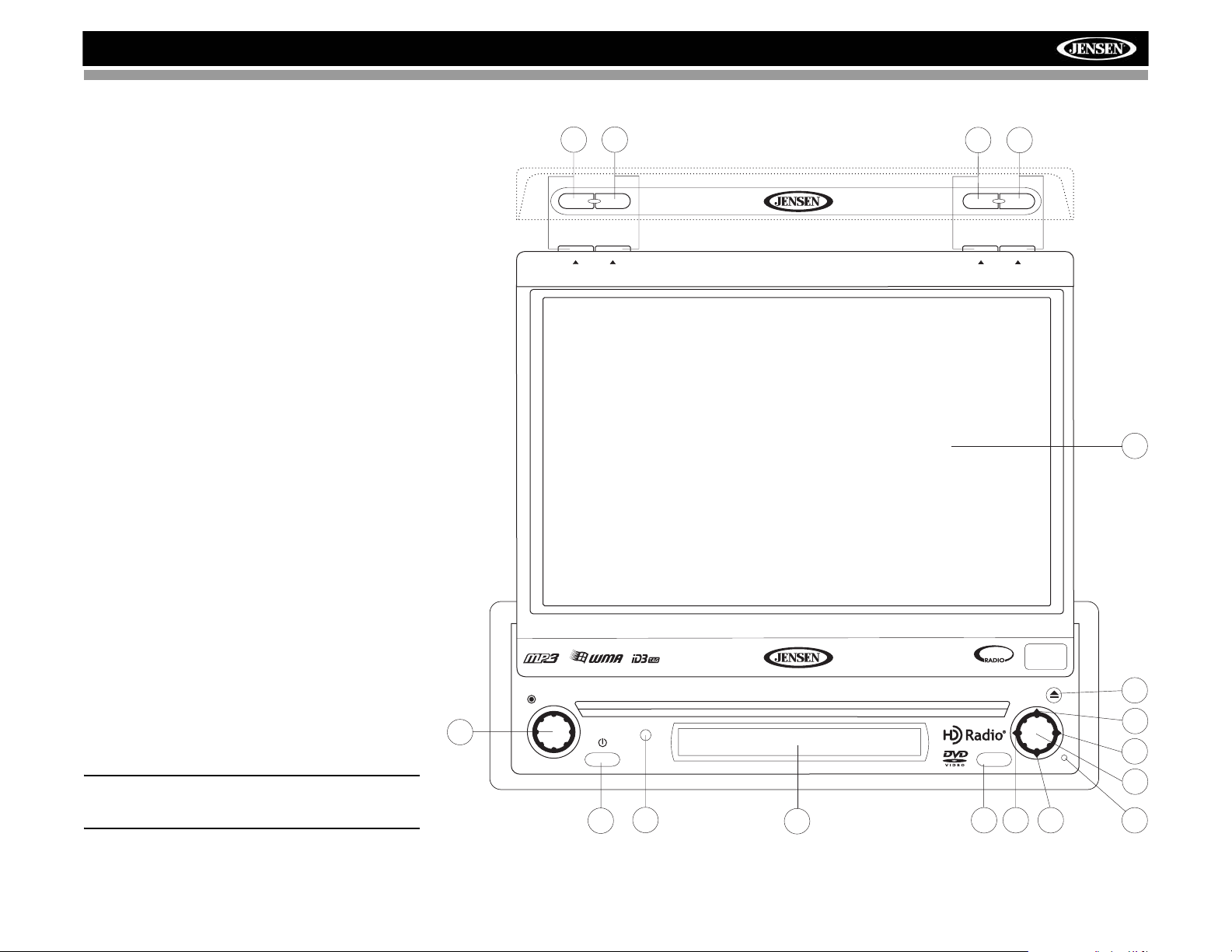
CONTROLS AND INDICATORS
Button Operation
1. OPEN
Press to activate the automatic mechanical system and move
the TFT monitor into viewing position. Press again to close
the TFT.
2. WIDE/DISP
Press to adjust the display aspect of the picture to one of two
settings: Full or Normal.
With the monitor closed, press the DISP button to cycle
through information available on the LCD screen.
When the NAV101 is connected to the VM9312HD, press
and hold to display the navigation user interface. The TFT
screen must be open for this function to operate.
3. PICTURE/AS
Press to adjust the Brightness and Contrast. Press the
AUDIO button (5) to move between Brightness to Contrast.
Turn the rotary encoder (5) to adjust the setting for the
selected option.
Press and hold the AS button to automatically store strong
radio stations in the preset channels for the current band.
4. TILT/BAND
Press to activate the tilt function. Use the joystick to make
adjustments while the red tilt icon is flashing. Press once to
adjust the downward tilt angle of the screen one step at a
time or press and hold to adjust the angle in a continuous
motion.
With the monitor closed, press the BAND button to change
the AM, FM or SAT band.
5. AUDIO
Rotate to adjust the volume. Press and release to enter and/
or confirm audio settings.
6. SRC
Press once to select playing mode.
7. LCD Display
8. MUTE
Press to silence the receiver. Press again to resume previous
volume level.
NOTE: The VM9312HD features Softmute, which will
allow the volume to increase or decrease gradually when
the MUTE function is activated or deactivated.
5
PRESS AUDIO
4
BAND
PICTURE
TILT
VM9312HD
SRC
6
3
AS
2
DISP
WIDE
1
OPEN
CLOSE
17
SAT
READY
160
Watts
EJECT
16
15
MUTE
14
13
9
7
8
10 11
12
6
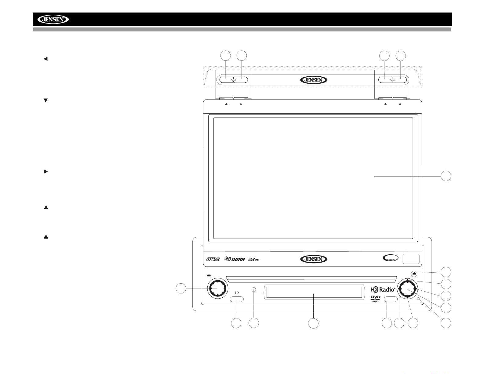
CONTROLS AND INDICATORS
9. IR Remote Control Receiver
10. ( )
DVD Mode: Press once to play back the previous chapter/
track.
TUNER Mode: Press once to auto-search for the previous
available radio station.
MENU Mode: Press once to move the cursor to the left.
11. ( )
DVD Mode: Press once for slow forward/slow reverse.
TUNER Mode: Press to go down one frequency step.
MENU Mode: Press once to move the cursor down.
12. RESET
Press to reset system settings to factory default (except the
password and parental lock setting).
13.Pause/Play/Enter
Press to pause or resume plaback or to confirm current
selection.
14. ( )
DVD Mode: Press once to enter the next chapter or track.
TUNER Mode: Press once to auto-search the next available
radio station.
MENU Mode: Press once to move the cursor to the right.
15. ( )
DVD Mode: Press once for fast forward/fast reverse.
TUNER Mode: Press to go up one frequency step.
MENU Mode: Press once to move the cursor up.
16. ( )
Press once for disc insertion/ejection.
Press and hold to reset core mechanism position.
17. TFT Display
PRESS AUDIO
4
BAND
PICTURE
TILT
VM9312HD
VM9312HD
3
AS
2
DISP
WIDE
READY
SAT
1
OPEN
CLOSE
EJECT
160
Watts
17
16
5
SRC
MUTE
15
14
13
9
6
7
8
10 11
12
7
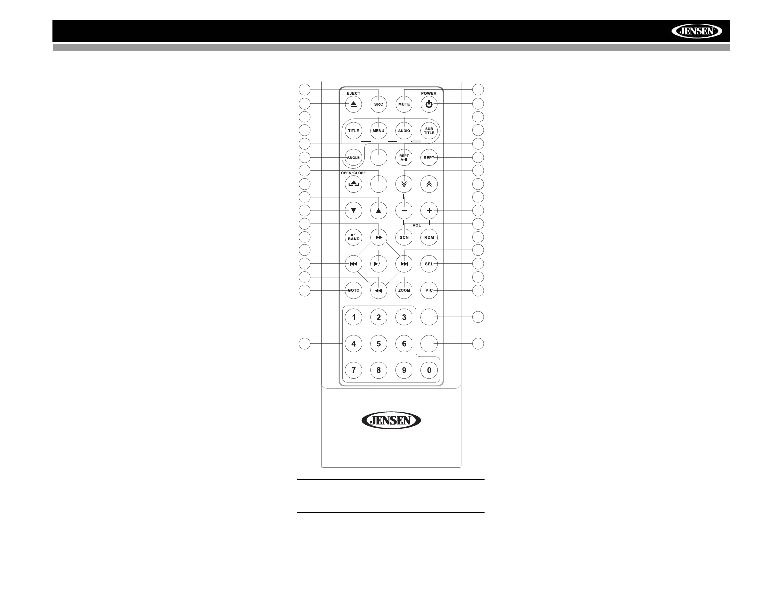
VM9312HD
REMOTE CONTROL
8
35
1
2
10
13
MUSIC PHOTOS VIDEO iPod
DISP
28
25
11
WIDE
TILT
12
14
PRESET
20
18
MENU
17
22
21
SLOW
SETUP
29
CLEAR
3
4
5
9
6
7
26
27
15
16
34
33
19
32
23
24
31
30
NOTE: Your remote control may differ slightly
from the one pictured here. The above diagram is
for illustrative purposes only.
8
 Loading...