


DV8000
Table of contents
 Loading...
Maintenance and Service
Guide
HP Pavilion dv8000 Notebook PC
Document Part Number: 403248-001
November 2005
This guide is a troubleshooting reference used for maintaining
and servicing the computer. It provides comprehensive
information on identifying computer features, components, and
spare parts; troubleshooting computer problems; and performing
computer disassembly procedures.

© Copyright 2005 Hewlett-Packard Development Company, L.P.
Microsoft and Windows are U.S. registered trademarks of Microsoft
Corporation. AMD, Turion, and combinations thereof, are trademarks of
Advanced Micro Devices, Inc. Bluetooth is a trademark owned by its
proprietor and used by Hewlett-Packard Company under license. SD Logo
is a trademark of its proprietor.
The information contained herein is subject to change without notice. The
only warranties for HP products and services are set forth in the express
warranty statements accompanying such products and services. Nothing
herein should be construed as constituting an additional warranty. HP shall
not be liable for technical or editorial errors or omissions contained herein.
Maintenance and Service Guide
HP Pavilion dv8000 Notebook PC
First Edition November 2005
Document Part Number: 403248-001

Contents
1 Product Description
1.1 Features . . . . . . . . . . . . . . . . . . . . . . . . . . . . . . . . . . . 1–2
1.2 Resetting the Computer. . . . . . . . . . . . . . . . . . . . . . . 1–4
1.3 Power Management. . . . . . . . . . . . . . . . . . . . . . . . . . 1–5
1.4 External Components . . . . . . . . . . . . . . . . . . . . . . . . 1–6
1.5 Design Overview. . . . . . . . . . . . . . . . . . . . . . . . . . . 1–24
2 Troubleshooting
2.1 Computer Setup. . . . . . . . . . . . . . . . . . . . . . . . . . . . . 2–1
Accessing Computer Setup . . . . . . . . . . . . . . . . . . . . 2–2
Computer Setup Defaults . . . . . . . . . . . . . . . . . . . . . 2–2
Selecting from the File Menu . . . . . . . . . . . . . . . . . . 2–3
Selecting from the Security Menu . . . . . . . . . . . . . . 2–4
Selecting from the Tools Menu. . . . . . . . . . . . . . . . . 2–5
Selecting from the Advanced Menu . . . . . . . . . . . . . 2–6
2.2 Troubleshooting Flowcharts . . . . . . . . . . . . . . . . . . . 2–7
Maintenance and Service Guide iii

Contents
3 Illustrated Parts Catalog
3.1 Serial Number Location . . . . . . . . . . . . . . . . . . . . . . 3–1
3.2 Computer Major Components. . . . . . . . . . . . . . . . . . 3–2
3.3 Display Assembly Subcomponents. . . . . . . . . . . . . 3–10
3.4 Plastics Kit . . . . . . . . . . . . . . . . . . . . . . . . . . . . . . . 3–12
3.5 Cable Kit . . . . . . . . . . . . . . . . . . . . . . . . . . . . . . . . . 3–13
3.6 Mass Storage Devices . . . . . . . . . . . . . . . . . . . . . . . 3–14
3.7 Miscellaneous (Not Illustrated). . . . . . . . . . . . . . . . 3–16
3.8 Sequential Part Number Listing . . . . . . . . . . . . . . . 3–17
4 Removal and Replacement Preliminaries
4.1 Tools Required . . . . . . . . . . . . . . . . . . . . . . . . . . . . . 4–1
4.2 Service Considerations . . . . . . . . . . . . . . . . . . . . . . . 4–2
Plastic Parts . . . . . . . . . . . . . . . . . . . . . . . . . . . . . . . . 4–2
Cables and Connectors . . . . . . . . . . . . . . . . . . . . . . . 4–2
4.3 Preventing Damage to Removable Drives . . . . . . . . 4–3
4.4 Preventing Electrostatic Damage . . . . . . . . . . . . . . . 4–4
4.5 Packaging and Transporting Precautions . . . . . . . . . 4–5
4.6 Workstation Precautions . . . . . . . . . . . . . . . . . . . . . . 4–6
4.7 Grounding Equipment and Methods . . . . . . . . . . . . . 4–6
iv Maintenance and Service Guide

5 Removal and Replacement Procedures
5.1 Serial Number . . . . . . . . . . . . . . . . . . . . . . . . . . . . . . 5–2
5.2 Disassembly Sequence Chart . . . . . . . . . . . . . . . . . . 5–3
5.3 Preparing the Computer for Disassembly . . . . . . . . . 5–5
5.4 Hard Drive. . . . . . . . . . . . . . . . . . . . . . . . . . . . . . . . . 5–7
5.5 Computer Feet. . . . . . . . . . . . . . . . . . . . . . . . . . . . . 5–11
5.6 Memory Module . . . . . . . . . . . . . . . . . . . . . . . . . . . 5–12
5.7 Mini PCI Communications Module . . . . . . . . . . . . 5–16
5.8 RTC Battery . . . . . . . . . . . . . . . . . . . . . . . . . . . . . . 5–18
5.9 Optical Drive. . . . . . . . . . . . . . . . . . . . . . . . . . . . . . 5–20
5.10 Switch Cover. . . . . . . . . . . . . . . . . . . . . . . . . . . . . 5–22
5.11 Keyboard Assembly Frame. . . . . . . . . . . . . . . . . . 5–24
5.12 LED Board . . . . . . . . . . . . . . . . . . . . . . . . . . . . . . 5–28
5.13 Keyboard . . . . . . . . . . . . . . . . . . . . . . . . . . . . . . . . 5–30
5.14 Display Assembly . . . . . . . . . . . . . . . . . . . . . . . . . 5–32
5.15 Top Cover . . . . . . . . . . . . . . . . . . . . . . . . . . . . . . . 5–43
5.16 System Board . . . . . . . . . . . . . . . . . . . . . . . . . . . . 5–50
5.17 Bluetooth Module . . . . . . . . . . . . . . . . . . . . . . . . . 5–57
5.18 Modem Connector Cable . . . . . . . . . . . . . . . . . . . 5–60
5.19 USB Board . . . . . . . . . . . . . . . . . . . . . . . . . . . . . . 5–62
5.20 Speakers . . . . . . . . . . . . . . . . . . . . . . . . . . . . . . . . 5–64
5.21 Heat Sink. . . . . . . . . . . . . . . . . . . . . . . . . . . . . . . . 5–67
5.22 Processor . . . . . . . . . . . . . . . . . . . . . . . . . . . . . . . . 5–70
5.23 Fan Assembly . . . . . . . . . . . . . . . . . . . . . . . . . . . . 5–72
5.24 PC Card Assembly . . . . . . . . . . . . . . . . . . . . . . . . 5–76
Contents
Maintenance and Service Guide v

Contents
6 Specifications
A Connector Pin Assignments
B Power Cord Set Requirements
C Screw Listing
D Display Component Recycling
vi Maintenance and Service Guide
1
Product Description
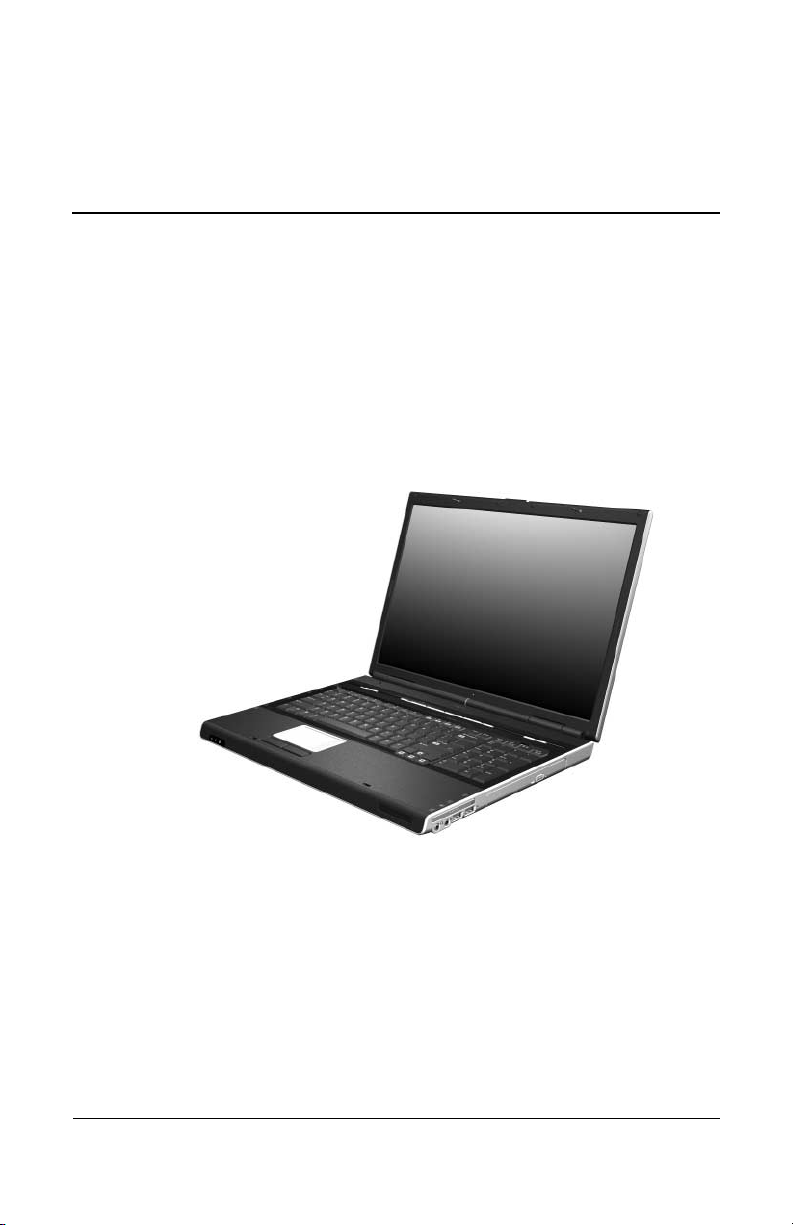
The HP Pavilion dv8000 Notebook PC offers advanced
modularity, AMD Turion™ 64 Mobile Technology processors,
and extensive multimedia support.
HP Pavilion dv8000 Notebook PC
Maintenance and Service Guide 1–1

Product Description
1.1 Features
■ AMD Turion 64 ML-40 (2.2-GHz), ML-37 (2.0-GHz), or
ML-30 (1.6-GHz) processors, all with 1-MB L2 cache,
or ML-32 (1.8-GHz) processor with 512-MB L2 cache,
varying by computer model
■ 17.0-inch, WSXGA+, TFT (1680 × 1050) with BrightView
or 17.0-inch, WXGA+, TFT (1440 × 900) with BrightView
display, varying by computer model
■ 120-, 100-, or 80-GB high-capacity hard drive, varying by
computer model
■ 256-MB DDR1 synchronous DRAM (SDRAM) at 333 MHz,
expandable to 2.0 GB
■ Microsoft® Windows® XP Home Edition or Windows XP
Professional, varying by computer model
■ Full-size Windows keyboard with full-size numeric keypad
■ TouchPad pointing device, including dedicated vertical scroll
region
■ Integrated 10Base-T/100Base-TX Ethernet local area
network (LAN) network interface card (NIC) with RJ-45 jack
■ Integrated high-speed 56K modem with RJ-11 jack
■ Integrated wireless support for Mini PCI IEEE 802.11a/b/g
WLAN device
■ Support for one Type I or Type II PC Card slot, with support
for both 32-bit (CardBus) and 16-bit PC Cards
■ Support for ExpressCard slot
1–2 Maintenance and Service Guide

Product Description
■ External 65-watt AC adapter with 3-wire power cord
■ 8-cell Li-Ion battery pack
■ Stereo speakers
■ Volume up, volume mute, and volume down buttons
■ QuickPlay buttons
■ Support for the following optical drives:
❏ DVD±RW and CD-RW Double Layer Combo Drive with
LightScribe
❏ DVD±RW and CD-RW Double Layer Combo Drive
❏ DVD/CD-RW Combo Drive
■ Connectors:
❏ Audio-in (microphone)
❏ Audio-out (headphone)
❏ Digital Media Slot
❏ Expansion port 2
❏ ExpressCard slot
❏ External monitor
❏ IEEE 1394
❏ PC Card
❏ Power
❏ RJ-11 (modem)
❏ RJ-45 (network)
❏ S-Video-out
❏ Universal Serial Bus (USB) v. 2.0 (4 ports)
Maintenance and Service Guide 1–3

Product Description
1.2 Resetting the Computer
If the computer you are servicing has an unknown password,
follow these steps to clear the password. These steps also
clear CMOS:
1. Enter an incorrect password and press
2. Repeat Step 1 two times.
After the third entry of the incorrect password, the computer
responds with a “System Disabled” message and provides an
override password.
3. Access MS/DOS by clicking Start > All Programs >
Accessories > Command Prompt.
4. Enter “unlock6 xxxxx 0,” where “xxxxx” is the password
generated by the computer in Step 2.
The computer responds with another system-generated
password. This password can be used to reset the computer
and clear all CMOS settings.
enter.
1–4 Maintenance and Service Guide

1.3 Power Management
The computer comes with power management features that
extend battery operating time and conserve power. The
computer supports the following power management features:
■ Standby
■ Hibernation
■ Setting customization by the user
■ Hotkeys for setting the level of performance
■ Battery calibration
■ Lid switch standby/resume
■ Power button
■ Advanced Configuration and Power Management (ACPM)
compliance
Product Description
Maintenance and Service Guide 1–5

Product Description
1.4 External Components
The external components on the front of the computer are shown
below and described in Table 1-1.
Front Components
1–6 Maintenance and Service Guide

Product Description
Tabl e 1-1
Front Components
Item Component Function
1Power light ■ On: Computer is turned on.
■ Off: Computer is off or in hibernation.
■ Blinking: Computer is in standby.
2Battery light ■ On: A battery pack is charging or is close
to full charge capacity.
■ Off: If the computer is plugged into an
external power source, the light is turned
off when all batteries in the computer are
fully charged. If the computer is not
plugged into an external power source,
the light stays off until the battery
reaches a low-battery condition.
■ Blinking: A battery pack that is the only
available power source has reached a
low-battery condition. When the battery
reaches a critical low-battery condition,
the battery light begins blinking quickly.
3 Integrated Drive
Electronics (IDE)
drive light
4 Speakers Produce stereo sound.
5 Display release latch Opens the computer.
Maintenance and Service Guide 1–7
On or blinking: The internal hard drive or an
optical drive is being accessed.
Product Description
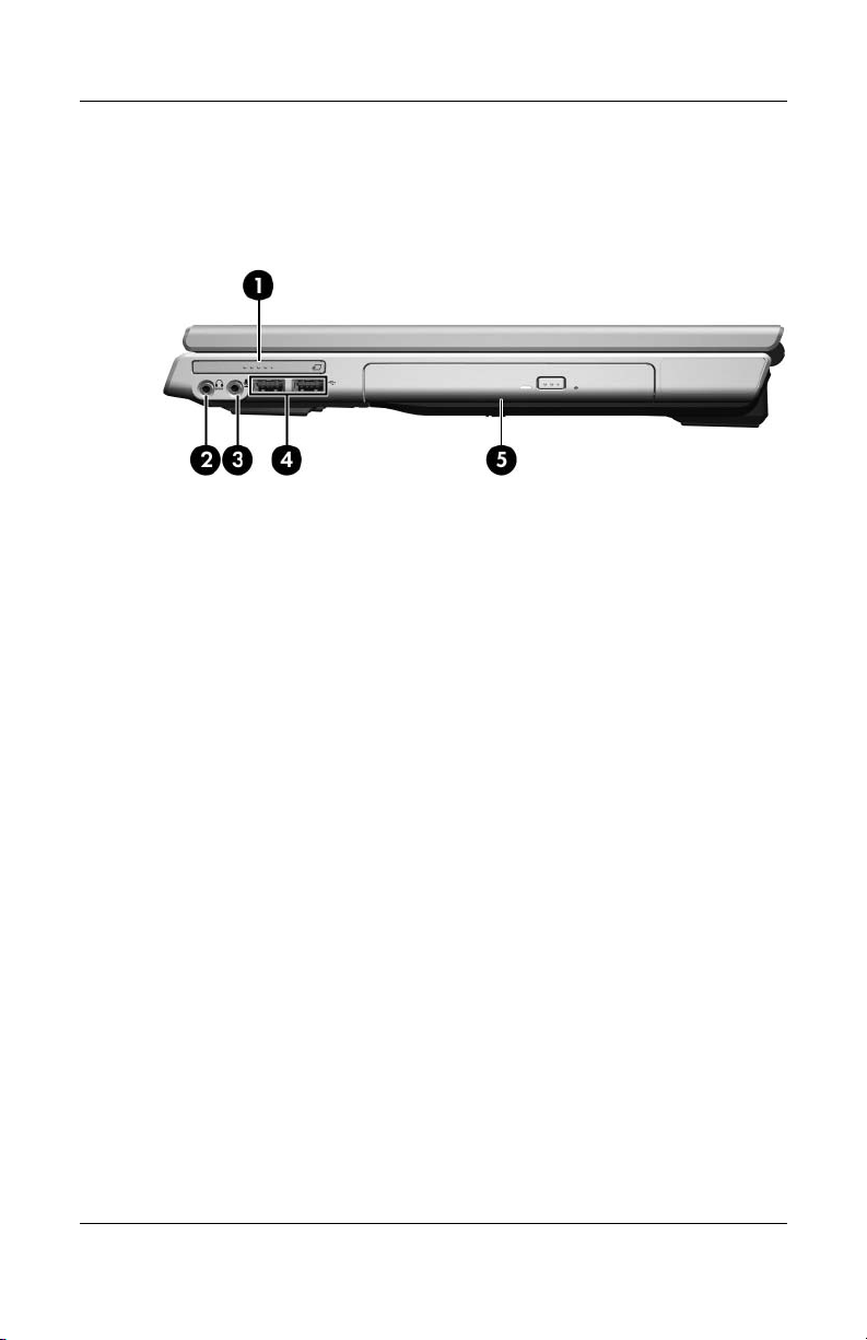
The external components on the right side of the computer are
shown below and described in Table 1-2.
Right-Side Components
1–8 Maintenance and Service Guide

Product Description
Tabl e 1-2
Right-Side Components
Item Component Function
1 ExpressCard slot Supports an optional ExpressCard.
2Audio-out
(headphone) jack
3 Audio-in (microphone)
jack
4 USB ports (2) Connect optional USB devices.
5 Optical drive Supports an optical disc, such as a CD
Connects an optional headphone or
powered stereo speakers. Also connects
the audio function of an audio/video device,
such as a television or VCR.
Connects an optional stereo microphone.
or DVD.
Maintenance and Service Guide 1–9
Product Description
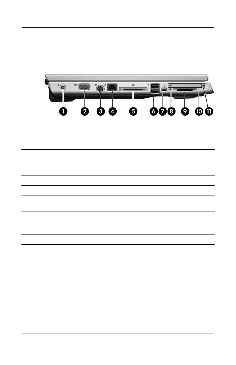
The external components on the left side of the computer are
shown below and described in Table 1-3.
Left-Side Components
Tabl e 1-3
Left-Side Components
Item Component Function
1 Power connector Connects the AC adapter cable.
2 Monitor port Connects an optional VGA monitor or
projector.
3 S-Video-out jack Connects the video function of an optional
S-Video device, such as a television, VCR,
or video capture card.
4 RJ-45 (network) jack Connects a network cable (not included).
1–10 Maintenance and Service Guide

Tabl e 1-3
Product Description
Left-Side Components
Item Component Function
5 Expansion port 2 Connects the computer to an optional
docking device.
✎
6 USB ports (2) Connect optional USB devices.
7 1394 port (4-pin) Connects an optional 1394a device such as
a scanner, a digital camera, or a digital
camcorder.
8 Digital Media Slot light On: An optional digital card is being
accessed.
9 Digital Media Slot Supports the following optional digital
cards: SD (Secure Digital) Memory Card,
SD I/O Card, Memory Stick, Memory Stick
Pro, MultiMediaCard, xD-Picture Card, and
SmartMedia.
10 PC Card slot Supports an optional Type I or Type II
32-bit (CardBus) or 16-bit PC Card.
11 PC Card eject button Ejects PC Cards from the PC Card slot.
(Continued)
The computer has only one
expansion port. The term
describes the type of
port 2
expansion port.
expansion
Maintenance and Service Guide 1–11

Product Description
The external components on the rear panel of the computer are
shown below and described in Table 1-4.
Rear Panel Components
1–12 Maintenance and Service Guide

Product Description
Tabl e 1-4
Rear Panel Components
Item Component Function
1 Security cable slot Attaches an optional security cable to the
computer.
The purpose of security solutions is
✎
to act as a deterrent. These solutions
do not prevent the product from
being mishandled or stolen.
2 RJ-11 (modem) jack Connects a modem cable (not included).
3 Battery bay Holds a battery pack.
4 Wireless light On: One or more internal wireless devices
have been turned on.
To establish a wireless connection, a
✎
wireless network must already be set
up.
5 Vent Provides airflow to cool internal
components.
To prevent overheating, do not
Ä
obstruct vents. Do not allow a hard
surface, such as a printer, or a soft
surface, such as pillows or thick rugs
or clothing, to block airflow.
Maintenance and Service Guide 1–13
Product Description
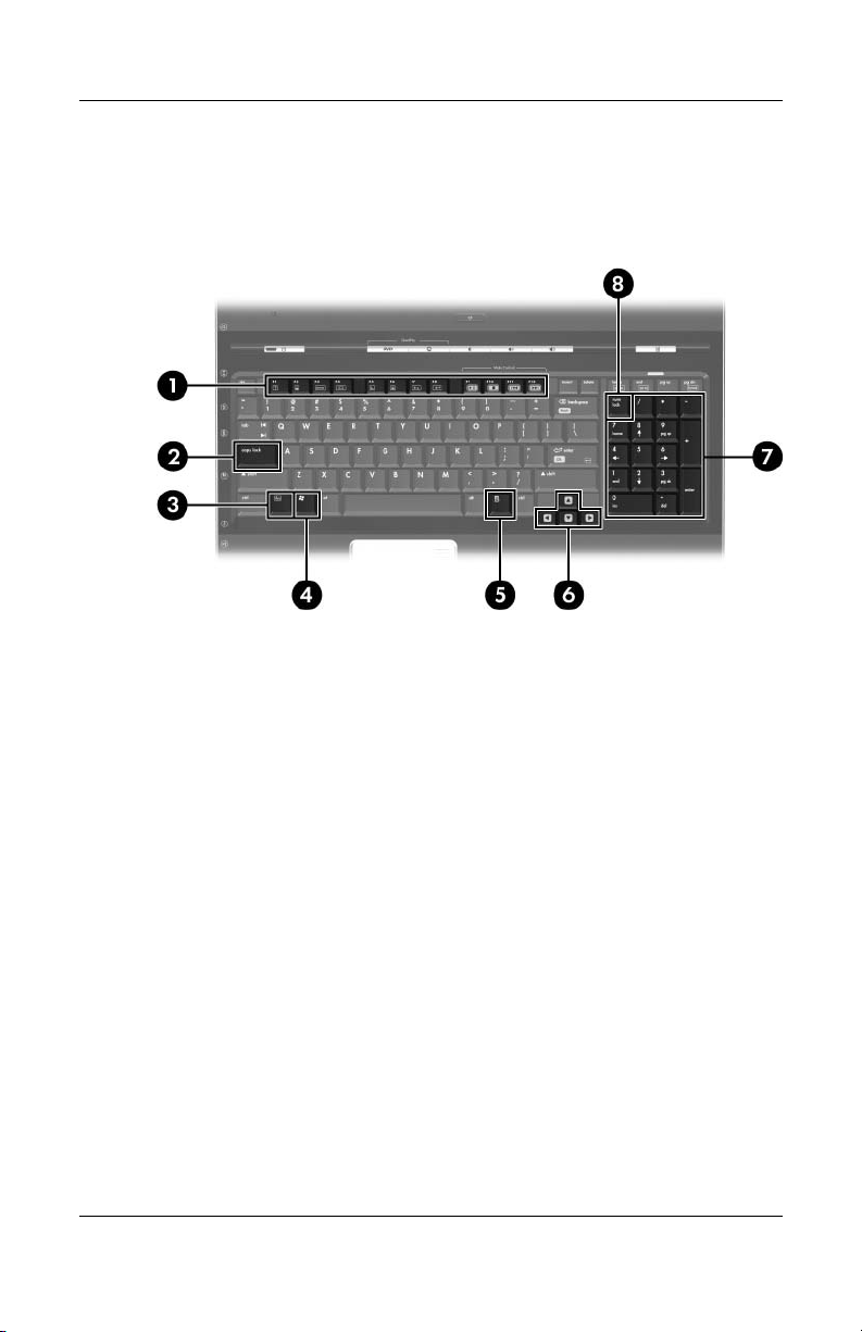
The standard keyboard components of the computer are shown
below and described in Table 1-5.
Standard Keyboard Components
1–14 Maintenance and Service Guide

Product Description
Table 1-5
Standard Keyboard Components
Item Component Function
1 f1 to f12 keys (12) Perform system and application tasks.
When combined with
perform additional tasks as hotkeys.
2 caps lock key Enables caps lock and turns on the caps
lock light.
fn, function keys
3 fn
4 Windows logo key Displays the Microsoft Windows Start
5Windows
6 Arrow keys Move the cursor around the screen.
7 Numeric keypad keys
8 num lock key Enables numeric lock, turns on the
key Combines with other keys to perform
system tasks as hotkeys. For example,
fn+f7 decreases screen
applications key
(16)
pressing
brightness.
menu.
Displays a shortcut menu for items
beneath the pointer.
Can be used like the keys on an external
numeric keypad.
embedded numeric keypad, and turns
on the num lock light.
Maintenance and Service Guide 1–15
Product Description
The computer top components are shown below and described in
Table 1-6.
Top Components
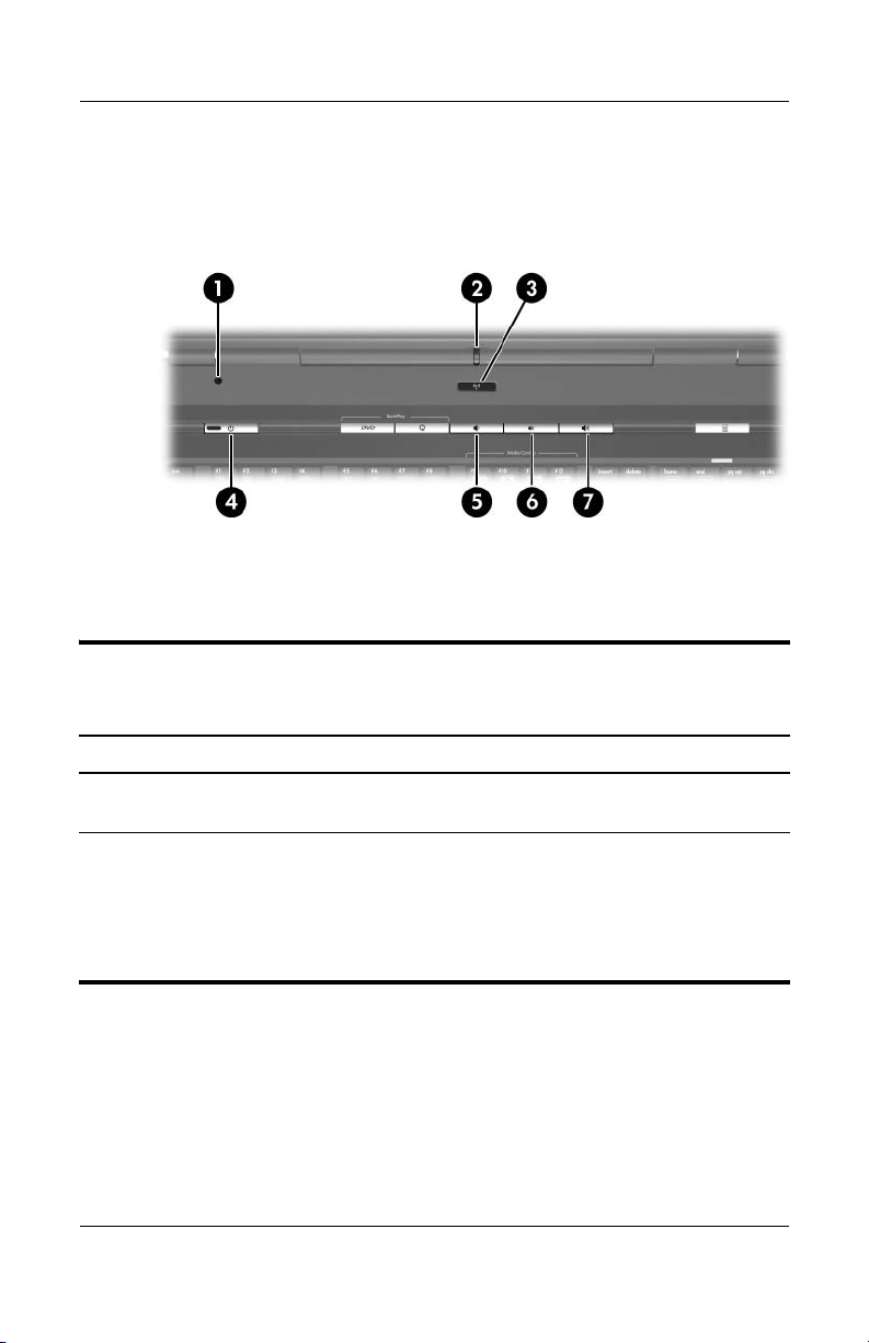
Table 1-6
Top Components
Item Component Function
1 Display switch Initiates standby if the display is closed
when the computer is on.
2 Wireless light On: One or more internal wireless devices
have been turned on.
To establish a wireless connection,
✎
a wireless network must already be
set up.
1–16 Maintenance and Service Guide

Table 1-6
Product Description
Top Components
Item Component Function
3 Wireless button Turns the wireless functionality on or off,
4Power light ■ On: The computer is on.
Power button When the computer is
(Continued)
but does not create a wireless connection.
To establish a wireless connection,
✎
a wireless network must already be
set up.
■ Blinking: The computer is in standby.
■ Off: The computer is off or in
hibernation.
■ Off, press to turn on the computer.
■ On, press to enter hibernation.
■ In standby, briefly press to exit standby.
■ In hibernation, briefly press to exit
hibernation.
If the computer has stopped responding
and Microsoft® Windows® shutdown
procedures cannot be used, press and
hold the power button for at least
5 seconds to turn off the computer.
5 Volume down button Decreases system volume.
6 Volume mute button Mutes or restores volume.
7 Volume up button Increases system volume.
Maintenance and Service Guide 1–17
Product Description
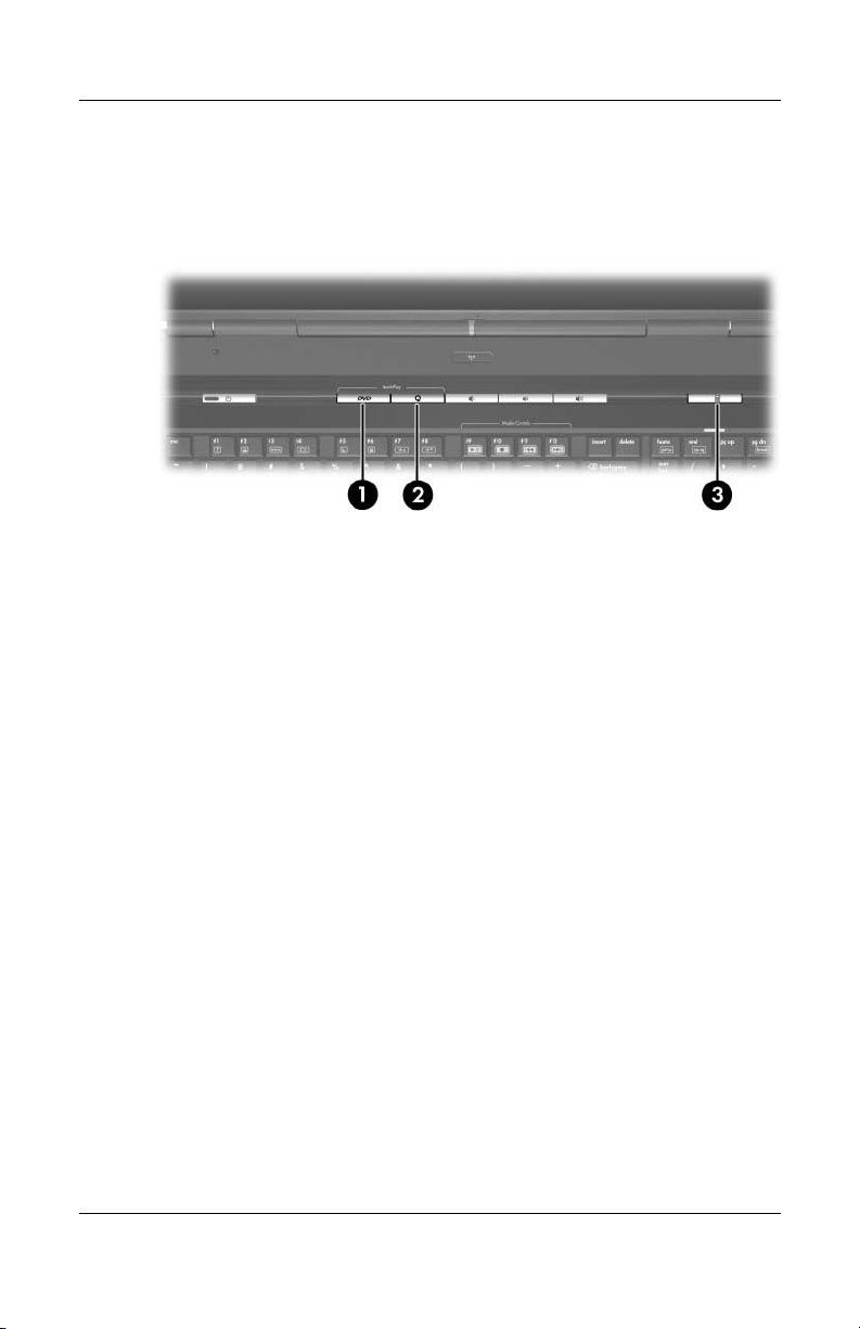
The Quick Play and Quick Launch buttons are shown below and
described in Table 1-7.
Top Components
1–18 Maintenance and Service Guide

Product Description
Table 1-7
QuickPlay and Quick Launch Button Components
Item Component Function
1 DVD button Default button functions without QuickPlay
software:
When the computer is
■ On: Opens the default DVD application
to start a DVD in the optical drive.
■ Off: No function.
■ In standby: Resumes from standby into
Windows.
■ In hibernation: Restores from
hibernation into Windows.
Button functions with QuickPlay software:
When the computer is
■ On: Opens the default DVD application
to start a DVD in the optical drive.
■ Off: Opens QuickPlay to start a DVD in
the optical drive.
■ In standby: Resumes from standby into
Windows.
■ In hibernation: Restores from
hibernation into Windows.
Maintenance and Service Guide 1–19

Product Description
Table 1-7
QuickPlay and Quick Launch Button Components
Item Component Function
2 Media Button Default button functions without QuickPlay
software:
When the computer is
■ On: Opens the music application or the
Media menu, allowing you to select a
multimedia application.
■ Off: No function.
■ In standby: Resumes from standby into
Windows.
■ In hibernation: Restores from
hibernation into Windows.
Button functions with QuickPlay software:
When the computer is
■ On: Opens the music application or the
Media menu, allowing you to select a
multimedia application.
■ Off: Opens the music application or the
Media menu, allowing you to select a
multimedia application.
■ In standby: Resumes from standby into
Windows.
■ In hibernation: Restores from
hibernation into Windows.
(Continued)
3 Quick Launch
calculator button
1–20 Maintenance and Service Guide
Opens the Microsoft Windows calculator.
This button can also be reassigned to an
Internet or network destination or to any
software application or data file.
When you press the Quick Launch
✎
calculator button, num lock is
enabled.
Product Description
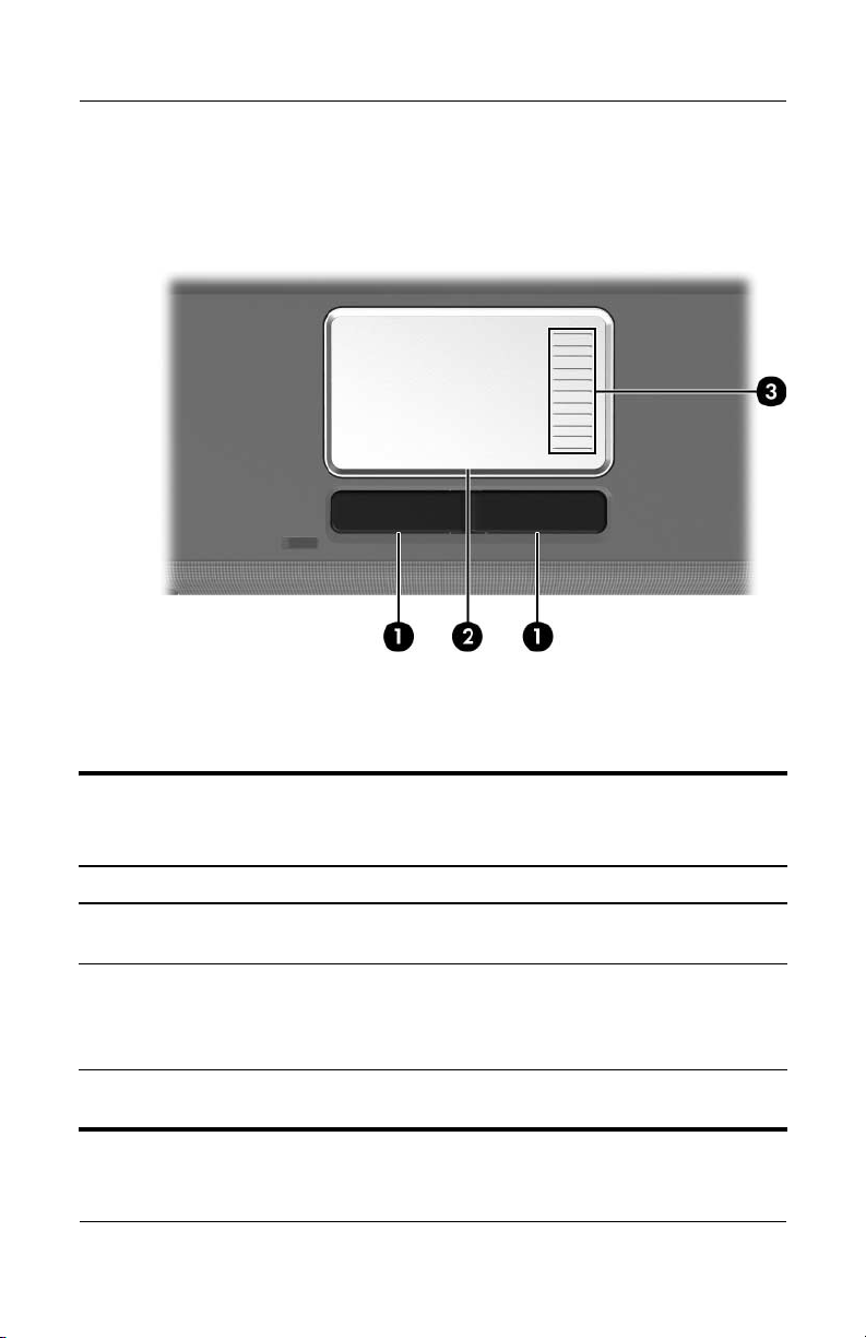
The computer TouchPad components are shown below and
described in Table 1-8.
TouchPad Components
Table 1-8
TouchPad Components
Item Component Function
1 Left and right
TouchPad buttons
2 TouchPad Moves the pointer and selects or activates
3 TouchPad vertical
scroll zone
Maintenance and Service Guide 1–21
Function like the left and right buttons on
an external mouse.
items on the screen. Can be set to perform
other mouse functions, such as scrolling,
selecting, and double-clicking.
Scrolls up or down.

Product Description
The external components on the bottom of the computer are
shown below and described in Table 1-9.
Bottom Components
Table 1 -9
Bottom Components
Item Component Function
1 Optical drive Supports an optical disc, such as a CD
or DVD.
2 Labels area Contains the serial number and other
information labels.
3 Battery pack release latch Releases a battery pack from the
battery bay.
4 Battery bay Holds a battery pack.
1–22 Maintenance and Service Guide

Table 1 -9
Product Description
Bottom Components
Item Component Function
5 Vents (2) Provide airflow to cool internal
6 Memory/Mini PCI module
compartment cover
(Continued)
components.
To prevent overheating, do not
Ä
obstruct vents. Do not allow a
hard surface, such as a printer, or
a soft surface, such as pillows
or thick rugs or clothing, to block
airflow.
■ Contains 2 memory module slots that
support replaceable memory
modules. The number of preinstalled
memory modules varies by computer
model.
■ Holds an optional wireless LAN
device (select models only).
To prevent an unresponsive
Ä
system and the display of a
warning message, install only a
Mini PCI device authorized for
use in your computer by the
governmental agency that
regulates wireless devices in
your country. If you install an
unauthorized device and then
receive a warning message,
remove the device to restore
computer functionality. Then
contact Customer Care.
7 Hard drive bay Holds the internal hard drive.
Maintenance and Service Guide 1–23

Product Description
1.5 Design Overview
This section presents a design overview of key parts and features
of the computer. Refer to Chapter 3, “Illustrated Parts Catalog,”
to identify replacement parts, and Chapter 5, “Removal and
Replacement Procedures,” for disassembly steps.
The system board provides the following device connections:
■ AMD Turion 64 processors
■ Audio
■ Digital media card
■ Display
■ ExpressCard
■ Hard drive
■ Keyboard
■ Memory module
■ Mini PCI communications devices
■ PC Card
■ To uc hP ad
CAUTION: To properly ventilate the computer, allow at least a 7.6-cm
Ä
(3-inch) clearance on the left and right sides of the computer.
The computer uses an electric fan for ventilation. The fan is
controlled by a temperature sensor and is designed to be turned
on automatically when high temperature conditions exist. These
conditions are affected by high external temperatures, system
power consumption, power management/battery conservation
configurations, battery fast charging, and software applications.
Exhaust air is displaced through the ventilation grill located on
the left side of the computer.
1–24 Maintenance and Service Guide
Loading...