


 Loading...
Graco Inc 12005, 12004, 309739, 12006, 12004X User Manual
...
Instructions-Parts List
Pistol Grip Flow Gun
309739D
For dispensing ambient temperature sealants and adhesives.
Important Safety Instructions
Read all warnings and instructions in this manual. Save these instructions.
See page 2 for part numbers and maxumum working pressure.
Model 12004X |
Models 12004 and 12005 |
Model 12006

Models
Models
Pistol Grip, Base Seal
Part Number |
Model |
Description |
|
|
|
2500 psi (17.2 MPa, 172 bar) maximum working pressure |
||
|
|
|
C27020 |
12004 |
Standard base seal |
|
|
|
C27031 |
12004X |
Two stage, easy pull |
|
|
|
C27067 |
12005 |
Balanced piston |
|
|
|
Contents
Models . . . . . . . . . . . . . . . . . . . . . . . . . . . . . . . . . . . |
2 |
Warnings . . . . . . . . . . . . . . . . . . . . . . . . . . . . . . . . . 3
Grounding and Electrical Requirements . . . . . . . . 4
Installation . . . . . . . . . . . . . . . . . . . . . . . . . . . . . . . . 5
Pressure Relief Procedure . . . . . . . . . . . . . . . . . 5
Trigger Lock . . . . . . . . . . . . . . . . . . . . . . . . . . . . . 5
Troubleshooting . . . . . . . . . . . . . . . . . . . . . . . . . . . . 6
Service . . . . . . . . . . . . . . . . . . . . . . . . . . . . . . . . . . . 8
Models 12004, 12004X . . . . . . . . . . . . . . . . . . . . 8
Model 12005 . . . . . . . . . . . . . . . . . . . . . . . . . . . . 9
Model 12006 . . . . . . . . . . . . . . . . . . . . . . . . . . . 11
Parts . . . . . . . . . . . . . . . . . . . . . . . . . . . . . . . . . . . . |
12 |
Models 12004 & 12004X . . . . . . . . . . . . . . . . . . 12
Model 12005 . . . . . . . . . . . . . . . . . . . . . . . . . . . 13
Model 12006 . . . . . . . . . . . . . . . . . . . . . . . . . . . 14
Technical Data . . . . . . . . . . . . . . . . . . . . . . . . . . . . 15
Graco Standard Warranty . . . . . . . . . . . . . . . . . . . 16
Graco Information . . . . . . . . . . . . . . . . . . . . . . . . . 16
Pistol Grip, Tip Seal
Part Number |
Model |
Description |
|
|
|
2000 psi (13.79 MPa, 137.9 bar) maximum working pressure
C27078 |
12006 |
Pistol Grip, Tip Seal |
|
|
|
2 |
309739 |
Warnings
Warnings
Warning
ELECTRIC SHOCK HAZARD
Improper grounding, setup, or usage of the system can cause electric shock.
•Turn off and disconnect power at main switch before disconnecting any cables and before servicing equipment.
•All electrical wiring must be done by a qualified electrician and comply with all local codes and regulations.
•Connect only to grounded power source.
SKIN INJECTION HAZARD
High pressure fluid from gun, hose leaks, or ruptured components will pierce skin. This may look like just a cut, but it is a serious injury that can result in amputation. Get immediate surgical treatment.
•Do not point gun at anyone or at any part of the body.
•Do not put your hand over the spray tip.
•Do not stop or deflect leaks with your hand, body, glove, or rag.
•Engage trigger lock when not spraying.
•Follow Pressure Relief Procedure on page 5 if the nozzle clogs and before cleaning, checking or servicing equipment.
TOXIC FLUID HAZARD
Toxic fluids or fumes can cause serious injury or death if splashed in the eyes or on the skin, inhaled, or swallowed.
•Read MSDS’s to know the specific hazards of the fluids you are using.
•Store hazardous fluid in approved containers and dispose of it according to applicable guidelines.
EQUIPMENT MISUSE HAZARD
Equipment misuse can cause death or serious injury.
•Do not exceed maximum working pressure or temperature rating of lowest rated system component. See Technical Data in all equipment manuals.
•Use fluids and solvents that are compatible with equipment wetted parts. See Technical Data in all equipment manuals. Read fluid and solvent manufacturers warnings.
•Check equipment daily. Repair or replace worn or damaged parts immediately.
•Do not alter or modify equipment.
•For professional use only.
•Use equipment only for its intended purpose. Call your Graco distributor for information.
•Route hoses away from traffic areas, sharp edges, moving parts and hot surfaces.
•Do not use hoses to pull equipment.
309739 |
3 |
Grounding and Electrical Requirements
Grounding and Electrical Requirements
The following are minimum requirements for a basic dispensing system. Your system may include other equipment or objects that must be grounded. Check your local electrical code for detailed grounding instructions for your area and type of equipment.
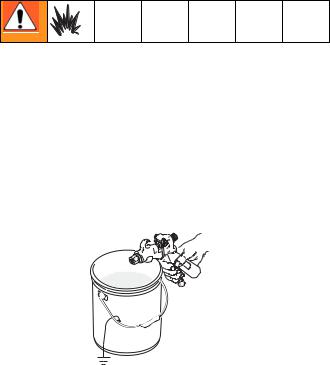
To maintain grounding continuity when flushing or relieving pressure, always hold a metal part of spray gun firmly to side of a grounded metal pail. Then trigger spray gun.
1.Pump: connect a ground wire and clamp to a true earth ground as shown in pump manual.
2.Applicator: ground through motor cable assembly.
3.Fluid and air hoses: only use electrically conductive material and air hoses.
4.Dispense gun: ground through connection of hose or cable.
5.Air compressor: follow manufacturer’s recommendations.
6.Object being sprayed: refer to local code.
7.Fluid supply container: refer to local code.
8.Solvent pails used for flushing: refer to local code.
ti3795a
4 |
309739 |
Installation
Installation
Inspect flow gun for shipping damage. If damage is found notify the carrier immediately.
 If material hose will be suspended by a hanger or
 tool balancer, route hose through the suspension device before securing each end of material hose.
1.Connect flow gun to any standard Graco hose assembly.
2.Connect the opposite end of the heated hose assembly to any fluid supply system. See Model table, page 2 for maximum fluid working pressure for your gun model.
3.Tighten fluid connections.
4.Before operating gun, squeeze and release trigger a few cycles. Observe action of cartridge assembly.
Pressure Relief Procedure
To help prevent injuries, follow this procedure 
 when you shut off the flow gun and before checking or adjusting any part of gun.
1.Shut off air to pump.
2.Close bleed-type master air valve (required in your system).
3.Hold metal part of spray gun firmly to side of grounded metal pail. Trigger gun to relieve pressure.
ti3795a
4.Open drain valve and/or pump bleeder valve having a container ready to catch the drainage.
5.Leave drain valve open until you are ready to spray/dispense again.
If you suspect the tip/nozzle or hose is completely clogged or that pressure has not been fully relieved after following the above steps, VERY SLOWLY loosen the retaining nut or hose end coupling to relieve pressure gradually. Then loosen it completely. Clear tip/nozzle or hose.
Trigger Lock
Always engage trigger lock when you stop dispensing to prevent gun from being triggered accidentally by hand or if dropped or bumped.
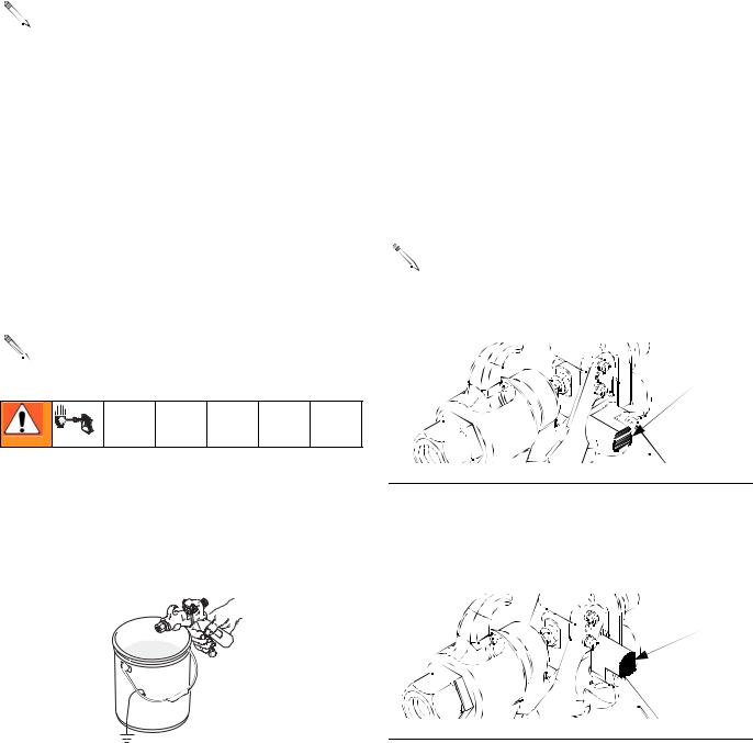
To engage trigger lock, release trigger and rotate lock downward. See Fig. 1.
Do not try to force trigger valve open with trigger 
 lock engaged. This could result in component fail-
ure.
Trigger Lock
Engaged
FIG. 1: Trigger Lock Engaged
To disengage trigger lock, rotate it upward. See Fig. 2.
Trigger Lock
Disengaged
FIG. 2: Trigger Lock Disengaged
309739 |
5 |
Loading...