


 Loading...
Dell™ XPS™ 8300 Service
Manual
Model: D03M Series |
Type: D03M001 |

Notes, Cautions, and Warnings
NOTE: A NOTE indicates important information that helps you make better use of your computer.
CAUTION: A CAUTION indicates either potential damage to hardware or loss of data and tells you how to avoid the problem.
WARNING: A WARNING indicates a potential for property damage, personal injury, or death.
____________________
Information in this document is subject to change without notice. © 2010 Dell Inc. All rights reserved.
Trademarks used in this text: Dell™, the DELL logo, and XPS™ are trademarks of Dell Inc.; Microsoft®, Windows®, and the Windows start button logo  are either trademarks or registered trademarks of Microsoft Corporation in the United States and/or other countries; Bluetooth® is a registered trademark owned by Bluetooth SIG, Inc. and is used by Dell under license.
Reproduction of these materials in any manner whatsoever without the written permission of Dell Inc. is strictly forbidden.
Regulatory model: D03M series |
Regulatory Type: D03M004 |
December 2010 |
Rev. A00 |

Contents
1 |
Technical Overview . . . . . . . . . . . . . . . . . . |
9 |
|
Inside View of Your Computer . . . . . . . . . . . . . . |
9 |
|
System Board Components . . . . . . . . . . . . . . . |
10 |
2 |
Before You Begin . . . . . . . . . . . . . . . . . . |
13 |
|
Technical Specifications . . . . . . . . . . . . . . . . |
13 |
|
Recommended Tools . . . . . . . . . . . . . . . . . . |
13 |
|
Turning Off Your Computer . . . . . . . . . . . . . . . |
13 |
|
Safety Instructions . . . . . . . . . . . . . . . . . . . |
14 |
3 |
Computer Cover . . . . . . . . . . . . . . . . . . . |
17 |
|
Removing the Computer Cover . . . . . . . . . . . . . |
17 |
|
Replacing the Computer Cover . . . . . . . . . . . . . |
18 |
4 |
Memory Module(s) . . . . . . . . . . . . . . . . . |
21 |
|
Removing the Memory Module(s) . . . . . . . . . . . . |
21 |
|
Replacing the Memory Module(s) . . . . . . . . . . . |
22 |
Contents 3

5 |
Front Bezel . . . . . . . . . . . . . . . . . . . . . . . |
27 |
|
Removing the Front Bezel . . . . . . . . . . . . . . . . |
27 |
|
Replacing the Front Bezel . . . . . . . . . . . . . . . . |
29 |
6 |
Graphics Card Bracket . . . . . . . . . . . . . . |
31 |
|
Removing the Graphics Card Bracket . . . . . . . . . . |
31 |
|
Replacing the Graphics Card Bracket . . . . . . . . . |
32 |
7 |
Wireless Mini-Card . . . . . . . . . . . . . . . . . |
33 |
|
Removing the Mini-Card . . . . . . . . . . . . . . . . . |
33 |
|
Replacing the Mini-Card . . . . . . . . . . . . . . . . |
34 |
8 |
PCI Express Cards . . . . . . . . . . . . . . . . . . |
37 |
|
Removing the Card Retention Bracket . . . . . . . . . |
37 |
|
Replacing the Card Retention Bracket . . . . . . . . . |
38 |
|
Removing PCI Express Cards . . . . . . . . . . . . . . |
39 |
|
Replacing PCI Express Cards . . . . . . . . . . . . . . |
41 |
|
Configuring Your Computer After Removing or Installing the PCI |
|
|
Express Card . . . . . . . . . . . . . . . . . . . . . . . |
42 |
9 |
Drives . . . . . . . . . . . . . . . . . . . . . . . . . . . |
45 |
|
Hard Drive . . . . . . . . . . . . . . . . . . . . . . . . |
45 |
|
Removing the Primary Hard Drive . . . . . . . . . |
45 |
4 Contents

|
Removing the Hard Drive Cage . . . . . . . . . . |
46 |
|
Removing the Secondary Hard Drive . . . . . . . |
47 |
|
Replacing the Secondary Hard Drive . . . . . . . |
48 |
|
Replacing the Hard Drive Cage . . . . . . . . . . |
49 |
|
Replacing the Primary Hard Drive . . . . . . . . . |
49 |
|
Optical Drive . . . . . . . . . . . . . . . . . . . . . . |
50 |
|
Removing the Optical Drive . . . . . . . . . . . . |
50 |
|
Replacing the Optical Drive . . . . . . . . . . . . |
51 |
|
Media Card Reader . . . . . . . . . . . . . . . . . . . |
54 |
|
Removing the Media Card Reader . . . . . . . . . |
54 |
|
Replacing the Media Card Reader . . . . . . . . . |
56 |
10 |
Top Cover . . . . . . . . . . . . . . . . . . . . . . . . |
57 |
|
Removing the Top Cover . . . . . . . . . . . . . . . . . |
57 |
|
Replacing the Top Cover . . . . . . . . . . . . . . . . |
59 |
11 |
Top I/O Panel . . . . . . . . . . . . . . . . . . . . . . |
61 |
|
Removing the Top I/O Panel . . . . . . . . . . . . . . . |
61 |
|
Replacing the Top I/O Panel . . . . . . . . . . . . . . |
63 |
12 |
Front USB Panel . . . . . . . . . . . . . . . . . . . |
65 |
|
Removing the Front USB Panel . . . . . . . . . . . . . |
65 |
|
Replacing the Front USB Panel . . . . . . . . . . . . . |
67 |
Contents 5

13 |
Bluetooth Assembly . . . . . . . . . . . . . . . . |
69 |
|
|
Removing the Bluetooth Assembly . . . . . . . . . . . |
69 |
|
|
Replacing the Bluetooth Assembly . . . . . . . . . . . |
71 |
|
14 |
Power Button Module . . . . . . . . . . . . . . . |
73 |
|
|
Removing the Power Button Module . . . . . . . . . . |
73 |
|
|
Replacing the Power Button Module . . . . . . . . . . |
75 |
|
15 |
Fans . . . . . . . . . . . . . . . . . . . . . . . . . . . . . |
77 |
|
|
Chassis Fan . . . . . . . . . . . . . . . . . . . . . . . |
77 |
|
|
Removing the Chassis Fan . . . . . . . . . . . . . |
77 |
|
|
Replacing the Chassis Fan . . . . . . . . . . . . . |
78 |
|
|
Processor Fan and Heat-Sink Assembly . . . . . . . . |
79 |
|
|
Removing the Processor Fan and Heat-Sink Assembly |
79 |
|
|
Replacing the Processor Fan and Heat-Sink Assembly |
81 |
|
16 |
Processor . . . . . . . . . . . . . . . . . . . . . . . . |
83 |
|
|
Removing the Processor . . . . . . . . . . . . . . . . . |
83 |
|
|
Replacing the Processor . . . . . . . . . . . . . . . . |
85 |
|
17 |
Coin-Cell Battery . . . . . . . . . . . . . . . . . . . |
89 |
|
|
Removing the Coin-Cell Battery . . . . . . . . . . . . . |
89 |
|
|
Replacing the Coin-Cell Battery . . . . . . . . . . . . |
90 |
|
6 Contents

18 Power Supply . . . . . . . . . . . . . . . . . . . . . 93
Removing the Power Supply
Replacing the Power Supply
. . . . . . . . . . . . . . |
93 |
. . . . . . . . . . . . . . |
95 |
19 |
System Board . . . . . . . . . . . . . . . . . . . . . |
97 |
|
Removing the System Board . . . . . . . . . . . . . . |
97 |
|
Replacing the System Board . . . . . . . . . . . . . . |
99 |
|
Entering the Service Tag in the BIOS . . . . . . . . . . |
101 |
20 |
System Setup Utility . . . . . . . . . . . . . . . |
103 |
|
Overview . . . . . . . . . . . . . . . . . . . . . . . . |
103 |
|
Entering System Setup Utility . . . . . . . . . . . |
103 |
|
System Setup Options . . . . . . . . . . . . . . . |
104 |
|
Boot Sequence . . . . . . . . . . . . . . . . . . . |
109 |
|
Clearing Forgotten Passwords . . . . . . . . . . . . . |
110 |
|
Clearing CMOS Passwords . . . . . . . . . . . . . . . |
112 |
21 |
Flashing the BIOS . . . . . . . . . . . . . . . . . |
115 |
Contents 7

8 Contents

3
Technical Overview
WARNING: Before working inside your computer, read the safety information that shipped with your computer. For additional safety best practices information, see the Regulatory Compliance Homepage at www.dell.com/regulatory_compliance.
WARNING: To avoid electrostatic discharge, ground yourself by using a wrist grounding strap or by periodically touching an unpainted metal surface (such as a connector on your computer).
CAUTION: Only a certified service technician should perform repairs on your computer. Damage due to servicing that is not authorized by Dell is not covered by your warranty.
Inside View of Your Computer
1
2
9 8 
7 
 3
3
 4
4
 5
5
6 
Technical Overview |
|
9 |
|
1 |
front bezel |
2 |
primary hard drive |
3 |
graphics card bracket (optional) |
4 |
secondary hard drive |
5 |
system board |
6 |
card retention clamp |
7 |
power supply |
8 |
primary optical drive |
9 |
secondary optical drive |
|
|
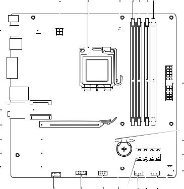
System Board Components
27 

26 
 25
25 

 24
24 


 23
23 


 22
22 


1 |
|
2 |
3 |
4 |
5 |
6 |
7 |
||||||||
|
|
|
|
|
|
|
|
|
|
|
|
|
|
|
|
|
|
|
|
|
|
|
|
|
|
|
|
|
|
|
|
|
|
|
|
|
|
|
|
|
|
|
|
|
|
|
|

 8
8
 9
9


 10
10


 11
11 


 12
12
21 |
20 |
19 |
18 17 |
16 15 |
14 |
13 |
10 |
|
Technical Overview |
|
1 |
power connector (PWR2) |
2 |
processor socket |
3 |
processor fan connector |
4 |
memory module connector |
|
(CPU_FAN) |
|
(DIMM3) |
5 |
memory module connector |
6 |
memory module connector |
|
(DIMM1) |
|
(DIMM4) |
7 |
memory module connector |
8 |
main power connector |
|
(DIMM2) |
|
(PWR1) |
9 |
password reset jumper (PSWD) |
10 |
CMOS reset jumper (RTCRST) |
11 |
SATA drive connector (SATA 0) |
12 |
power button connector |
|
|
|
(F_PANEL) |
13 |
SATA drive connector (SATA 1) |
14 |
front panel USB connector |
|
|
|
(F_USB1) |
15 |
SATA drive connector (SATA 2) |
16 |
front panel USB connector |
|
|
|
(F_USB3) |
17 |
SATA drive connector (SATA 3) |
18 |
battery socket (BATTERY) |
19 |
front panel USB connector |
20 |
front panel USB connector |
|
(F_USB2) |
|
(F_USB4) |
21 |
front panel audio connector |
22 |
PCI Express x1 card slot |
|
(F_AUDIO1) |
|
(PCI-EX1_3) |
23 |
PCI Express x1 card slot |
24 |
PCI Express x1 card slot |
|
(PCI-EX1_2) |
|
(PCI-EX1_1) |
25 |
PCI Express x16 card slot |
26 |
Mini-Card slot |
|
(PCI-EX16_1) |
|
(PCIE_MINICARD) |
27chassis fan connector (SYS_FAN 1)
Technical Overview |
|
11 |
|
12 |
|
Technical Overview |
|

1
Before You Begin
This manual provides instructions for removing and installing the components in your computer. Unless otherwise noted, each procedure assumes that the following conditions exist:
•You have performed the steps in "Turning Off Your Computer" on page 13 and "Safety Instructions" on page 14.
•You have read the safety information that shipped with your computer.
•A component can be replaced or—if purchased separately—installed by performing the removal procedure in reverse order.
Technical Specifications
For information on technical specifications of your computer, see the Setup Guide at support.dell.com/manuals.
Recommended Tools
The instructions in this document may require the following tools:
•Small flat-blade screwdriver
•Small Phillips screwdriver
•Plastic scribe
•BIOS executable update program available at support.dell.com
Turning Off Your Computer
CAUTION: To avoid losing data, save and close all open files and exit all open programs before you turn off your computer.
1Save and close all open files and exit all open programs.
2To shut down the operating system, click Start  and then click Shut Down.
Before You Begin |
|
13 |
|

3Ensure that the computer is turned off. If your computer did not automatically turn off when you shut down the operating system, press and hold the power button until the computer turns off.
Safety Instructions
Use the following safety guidelines to help protect your computer from potential damage and to help ensure your own personal safety.
WARNING: Before working inside your computer, read the safety information that shipped with your computer. For additional safety best practices information, see the Regulatory Compliance Homepage at www.dell.com/regulatory_compliance.
CAUTION: Only a certified service technician should perform repairs on your computer. Damage due to servicing that is not authorized by Dell is not covered by your warranty.
CAUTION: When you disconnect a cable, pull on its connector or on its pull-tab, not on the cable itself. Some cables have connectors with locking tabs; if you are disconnecting this type of cable, press in on the locking tabs before you disconnect the cable. As you pull connectors apart, keep them evenly aligned to avoid bending any connector pins. Also, before you connect a cable, ensure that both connectors are correctly oriented and aligned.
CAUTION: To avoid damaging the computer, perform the following steps before you begin working inside the computer.
1Ensure that the work surface is flat and clean to prevent the computer cover from being scratched.
2Turn off your computer (see "Turning Off Your Computer" on page 13) and all attached devices.
CAUTION: To disconnect a network cable, first unplug the cable from your computer and then unplug the cable from the network device.
3Disconnect all telephone or network cables from the computer.
4Disconnect your computer and all attached devices from their electrical outlets.
5Disconnect all attached devices from your computer.
6Press and eject any installed cards from the Media Card Reader.
7Press and hold the power button to ground the system board.
14 |
|
Before You Begin |
|

CAUTION: Before touching anything inside your computer, ground yourself by touching an unpainted metal surface, such as the metal at the back of the computer. While you work, periodically touch an unpainted metal surface to dissipate static electricity, which could harm internal components.
Before You Begin |
|
15 |
|
16 |
|
Before You Begin |
|

2
Computer Cover
WARNING: Before working inside your computer, read the safety information that shipped with your computer. For additional safety best practices information, see the Regulatory Compliance Homepage at www.dell.com/regulatory_compliance.
WARNING: To guard against likelihood of electric shock, laceration by moving fan blades, or other unexpected injuries, always unplug your computer from the electrical outlet before removing the cover.
WARNING: Do not operate your computer with any cover(s) (including computer covers, bezels, filler brackets, front-panel inserts, etc.) removed.
CAUTION: Only a certified service technician should perform repairs on your computer. Damage due to servicing that is not authorized by Dell is not covered by your warranty.
CAUTION: Ensure that sufficient space exists to support the computer with the cover removed—at least 30 cm (1 ft.) of desk top space.
Removing the Computer Cover
1Follow the instructions in "Before You Begin" on page 13.
2Lay the computer on its side with the computer cover facing up.
3Remove the thumbscrew that secures the computer cover to the chassis, using a screw driver, if necessary.
4Release the computer cover by sliding it away from the front of the computer.
5Lift the cover away from the computer and set it aside in a secure location.
Computer Cover |
|
17 |
|
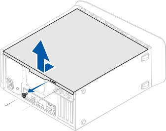
1
2
1 |
thumbscrew |
2 |
computer cover |
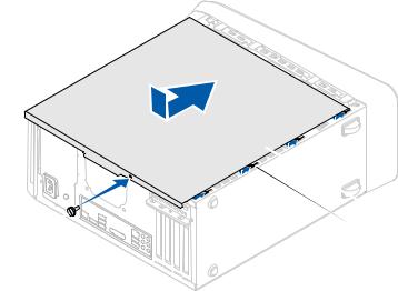
Replacing the Computer Cover
1Follow the instructions in "Before You Begin" on page 13.
2Connect all the cables and fold the cables out of the way.
3Ensure that no tools or extra parts are left inside the computer.
4Align the tabs at the bottom of the computer cover with the slots located along the edge of the chassis.
5Press the computer cover down and slide it towards the front of the computer.
6Replace the thumbscrew that secures the computer cover to the chassis.
18 |
|
Computer Cover |
|
 3
3  2
2
1
1 |
thumbscrew |
2 |
slots |
3 |
computer cover |
|
|
7 Place the computer in an upright position.
Computer Cover |
|
19 |
|
20 |
|
Computer Cover |
|
3
Memory Module(s)
WARNING: Before working inside your computer, read the safety information that shipped with your computer. For additional safety best practices information, see the Regulatory Compliance Homepage at www.dell.com/regulatory_compliance.
WARNING: To guard against electrical shock, always unplug your computer from the electrical outlet before removing the cover.
WARNING: Do not operate your computer with any cover(s) (including computer covers, bezels, filler brackets, front-panel inserts, etc.) removed.
CAUTION: Only a certified service technician should perform repairs on your computer. Damage due to servicing that is not authorized by Dell is not covered by your warranty.
Removing the Memory Module(s)
1Follow the instructions in "Before You Begin" on page 13.
2Remove the computer cover (see "Removing the Computer Cover" on page 17).
3Locate the memory module(s) on the system board (see "System Board Components" on page 10).
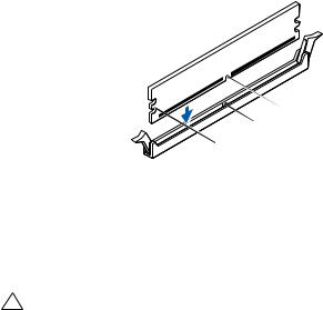
4Press out the securing clip at each end of the memory module connector.
Memory Module(s) |
|
21 |
|
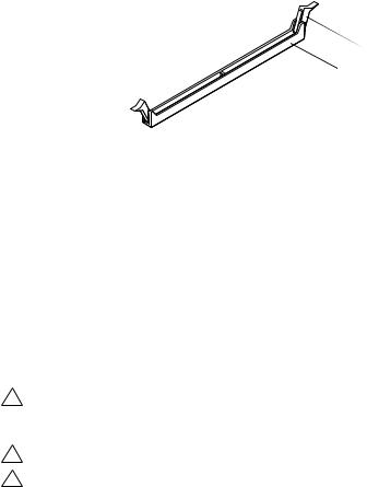
 2
2
 1
1
1 memory module connector |
2 securing clip |
5Grasp the memory module and pull it upwards.
If the memory module is difficult to remove, gently ease the memory module back and forth to remove it from the connector.
Replacing the Memory Module(s)
1Follow the instructions in "Before You Begin" on page 13.
2Press out the securing clip at each end of the memory module connector.
CAUTION: Only a certified service technician should perform repairs on your computer. Damage due to servicing that is not authorized by Dell is not covered by your warranty.
CAUTION: Do not install ECC or DDR3U memory modules.
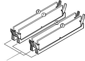
CAUTION: If you remove the original memory module(s) from your computer during a memory upgrade, keep them separate from any new module(s) that you may have, even if you purchased the new module(s) from Dell. If possible, do not pair an original memory module with a new memory module. Otherwise, your computer may not start properly. The recommended memory configurations are: matched memory module(s) installed in DIMM connectors 1 and 2 and another matched memory module(s) installed in DIMM connectors 3 and 4.
22 |
|
Memory Module(s) |
|
2 |
1 |
|
1 matched memory modules in |
2 matched memory modules in |
DIMM connectors 1 and 2 (white |
DIMM connectors 3 and 4 (black |
securing clips) |
securing clips) |
3Align the notch on the bottom of the memory module with the tab in the connector.
Memory Module(s) |
|
23 |
|

 4
4
 3
3
 2
2
 1
1
1 |
cutouts (2) |
2 |
tab |
3 |
notch |
4 |
memory module |
CAUTION: To avoid damage to the memory module, press the memory module straight down into the connector while you apply equal force to each end of the memory module.
4Insert the memory module into the connector until the memory module snaps into position.
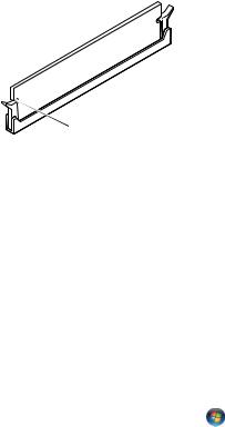
If you insert the memory module correctly, the securing clips snap into the cutouts at each end of the memory module.
24 |
|
Memory Module(s) |
|
 2
2
 1
1
1 |
cutouts (2) |
2 |
securing clip (snapped in |
|
|
|
position) |
5Replace the computer cover (see "Replacing the Computer Cover" on page 18).
6Connect your computer and devices to electrical outlets, and then turn them on.
If a message appears stating that the memory size has changed, press <F1> to continue.
7Log on to your computer.
To verify that the memory is installed correctly, click Start |
Control |
Panel System. |
|
Check the amount of memory (RAM) listed. |
|
Memory Module(s) |
|
25 |
|
26 |
|
Memory Module(s) |
|
4
Front Bezel
WARNING: Before working inside your computer, read the safety information that shipped with your computer. For additional safety best practices information, see the Regulatory Compliance Homepage at www.dell.com/regulatory_compliance.
WARNING: To guard against electrical shock, always unplug your computer from the electrical outlet before removing the cover.
WARNING: Do not operate your computer with any cover(s) (including computer covers, front bezels, filler brackets, front-panel inserts, etc.) removed.
CAUTION: Only a certified service technician should perform repairs on your computer. Damage due to servicing that is not authorized by Dell is not covered by your warranty.
Removing the Front Bezel
1Follow the instructions in "Before You Begin" on page 13.
2Remove the computer cover (see "Removing the Computer Cover" on page 17).
3Place the computer in an upright position.
4Grasp and release the front bezel tabs sequentially, one at a time by moving them outward from the front panel.
5Rotate and pull the front bezel away from the front of the computer to release the front bezel clamps from the front panel slots.
Front Bezel |
|
27 |
|
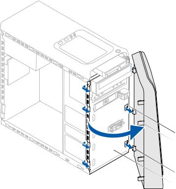
 1
1
 2
2
 3
3
 4
4
 5
5
1 |
front bezel |
2 |
front panel slots (3) |
3 |
front bezel tabs (4) |
4 |
front bezel clamps (3) |
5 |
front panel |
|
|
6 Set aside the front bezel in a secure location.
28 |
|
Front Bezel |
|
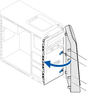
Replacing the Front Bezel
1Follow the instructions in "Before You Begin" on page 13.
2Align and insert the front bezel clamps into the front panel slots.
3Rotate the front bezel towards the computer until the front bezel tabs snap into place.
 1
1
 2
2
 3
3
 4
4
 5
5
Front Bezel |
|
29 |
|
1 |
front bezel |
2 |
front bezel tabs (4) |
3 |
front panel slots (3) |
4 |
front bezel clamps (3) |
5 |
front panel |
|
|
4Replace the computer cover (see "Replacing the Computer Cover" on page 18).
30 |
|
Front Bezel |
|
Loading...