


MTEK6000 SERIES USER'S MANUAL
MTEK6000 SERIES
Electronic Flow Corrector & Monitoring
Devices
Installation and Operating Instructions
January 2002
Part # 900315
January 2002

MTEK6000 SERIES USER'S MANUAL
TABLE OF CONTENTS
Chapter 1: Overview |
1-1 |
Overview ....................................................................................................... |
1-1 |
Hazardous Locations .................................................................................... |
1-1 |
Compliance ………….................................................................................... |
1-2 |
Warranty ………………................................................................................. |
1-2 |
Security Options ………………..................................................................... |
1-2 |
Chapter 2: Installation |
2-1 |
Unpacking ..................................................................................................... |
2-1 |
Initial Check-Out ........................................................................................... |
2-1 |
Power for the MTEK6000.............................................................................. |
2-2 |
Optional Power Supplies .........................................................…................. |
2-2 |
Mounting the Instrument on the Meter ......................................................... |
2-2 |
Setting Up the Index Assembly .................................................................... |
2-3 |
Unit and Index Rotation ....................................................................…… . |
2-4 |
Counter Masking ………………………………………………………………… |
2-4 |
Pulse Input to the MTEK6000.....................................................................… |
2-5 |
Wall and Pipe Mounting ..............................……........................................... |
2-5 |
Transducers in the MTEK6000 ..................................................................... |
2-7 |
Connecting the Pressure Tubing .................................................................. |
2-7 |
Installing the Thermal (Temperature) Probe ................................................. |
2-9 |
Installing the Pulse Output Wiring ................................................................. |
2-10 |
Communications ........................................................................................... |
2-12 |
RS-232C Serial (Direct) Communications ...............................…............ |
2-12 |
Modem Communications ……………………........................................... |
2-12 |
Connecting the Telephone Line ……………............................................ |
2-12 |
Grounding ..................................................................................................... |
2-15 |
Chapter 3: Operating Modes |
3-1 |
Sleep / Wake-up Mode .................................................................................... |
3-1 |
Display Mode ................................................................................................. |
3-1 |
Alarm Mode ................................................................................................... |
3-2 |
Viewing and Clearing Alarms With the Magnet ....................................... |
3-2 |
Memory (History Logging) ....................………….......................................... |
3-5 |
Configuration Mode ....................................................................................... |
3-6 |
Virtual Keypad and External Keypad Operation ....................................... |
3-6 |
Editing Parameters ................................................................................... |
3-6 |
Assigning Function Keys .......................................................................... |
3-8 |
Audit Trail ................................................................................................. |
3-8 |
Wake-up On Pulse ................................................................................... |
3-8 |
January 2002

MTEK6000 SERIES USER'S MANUAL
Analog Sampling ……..................................................................……..…. |
3-8 |
Special Key Combinations …………………............................................... |
3-9 |
Assigning The Number of Displayed Digits .............................................. |
3-9 |
Viewing and Clearing Alarms from the Keypad ....................................... |
3-9 |
Calibration Mode ........................................................................................... |
3-10 |
Calibrating the Pressure Transducer ....................................................... |
3-10 |
Calibrating the Temperature Transducer .................................................. |
3-11 |
Calibrating the Differential Pressure Transducer ...................................... |
3-12 |
Section 4: Optional Equipment |
4-1 |
Analog Output …………............................................................................... |
4-1 |
MTEK6000 Analog Output Specifications …...................................................... 4-3 |
|
Installing the Analog Output Loop …............................................................. |
4-3 |
Calibrating the Analog Output …................................…............................... |
4-3 |
Section 5: Maintenance and Software Packages |
5-1 |
Enclosure Maintenance ............................................................................... |
5-1 |
Changing the Battery ................................................................................... |
5-1 |
Calibration .................................................................................................... |
5-1 |
PcGas Meter Reader …................................................................................. |
5-2 |
PcGas Meter Utility ……................................................................................ |
5-2 |
PcGas Customer Monitor .............................................................................. |
5-2 |
MTEK Manager.................................................................................... ......... |
5-2 |
DC2000 ........................................................................................................ |
5-3 |
Appendix A : Process Configuration Standard |
A-1 |
Appendix B : Calculations |
B-1 |
Appendix C : Parameter Description |
C-1 |
Appendix D : Board Jumper Positions |
D-1 |
Appendix E : Certifications (CSA, UL, FCC drawings / statements) |
E-1 |
Appendix F : Warranty Information |
F-1 |
Appendix G : TII Telephone Circuit Surge Suppressor |
G-1 |
Appendix H : Hazardous Area Installation Control Drawings |
H-1 |
January 2002

MTEK6000 SERIES USER'S MANUAL
List of Figures |
|
Figure 1-1, MTEK6000 Exterior View . . . . . . . . . . . . . . . . . . . . . . . . . . . . . . . . |
1-3 |
Figure 1-2, MTEK6000 Interior View . . . . . . . . . . . . . . . . . . . . . . . . . . . . . . . . |
1-3 |
Figure 2-1, Power Connection and Configuration . . . . . . . . . . . . . . . . . . . . . . . |
2-1 |
Figure 2-2, Index Box Assembly . . . . . . . . . . . . . . . . . . . . . . . . . . . . . . . . . . . . |
2-3 |
Figure 2-3, Base Plate showing unit and index rotation . . . . . . . . . . . . . . . . . . |
2-4 |
Figure 2-4, Uncorrected counter masking for 8-digit counter . . . . . . . . . . . . . . |
2-4 |
Figure 2-5, Wall Mounting . . . . . . . . . . . . . . . . . . . . . . . . . . . . . . . . . . . . . . . . . |
2-6 |
Figure 2-6, Pipe Mounting . . . . . . . . . . . . . . . . . . . . . . . . . . . . . . . . . . . . . . . . . |
2-6 |
Figure 2-7, Pressure Connections . . . . . . . . . . . . . . . . . . . . . . . . . . . . . . . . . . . |
2-7 |
Figure 2-8, Typical Installation for MTEK6000 EFC . . . . . . . . . . . . . . . . . . . . . . |
2-8 |
Figure 2-9, Typical Installation for MTEK6000 EFM . . . . . . . . . . . . . . . . . . . . . . |
2-8 |
Figure 2-10, Temperature Probe Connection . . . . . . . . . . . . . . . . . . . . . . . . . . . |
2-9 |
Figure 2-11, Pulse Output Wiring . . . . . . . . . . . . . . . . . . . . . . . . . . . . . . . . . . . . |
2-10 |
Figure 2-12, Corrector Board Connector and Jumper Configuration Diagram . . |
2-14 |
Figure 3-1, Optional Keypad and Display . . . . . . . . . . . . . . . . . . . . . . . . . . . . . . |
3-7 |
Figure 4-1, Analog Output Option . . . . . . . . . . . . . . . . . . . . . . . . . . . . . . . . . . . . |
4-2 |
List of Tables |
|
Table 2-1, Thermowell Part Numbers . . . . . . . . . . . . . . . . . . . . . . . . . . . . . . . . . |
2-9 |
Table 2-2, Activity Indicator . . . . . . . . . . . . . . . . . . . . . . . . . . . . . . . . . . . . . . . . . |
2-13 |
Table A-1, Display mode and function keys for MTEK6000 EFC . . . . . . . . . . . |
A-1 |
Table A-2, Standard alarms for MTEK6000 EFC . . . . . . . . . . . . . . . . . . . . . . . . |
A-1 |
Table A-3, Historical data stored in MTEK6000 . . . . . . . . . . . . . . . . . . . . . . . . . |
A-1 |
Table A-4, Display mode and function keys with auxillary pressure . . . . . . . . . |
A-2 |
Table A-5, Standard alarms for MTEK6000 EFC w/ aux. pressure . . . . . . . . . . |
A-2 |
Table A-6, Historical data stored in MTEK6000 EFC w/ aux. pressure . . . . . . . |
A-2 |
Table A-7, Display mode and func. keys with 2 auxillary pressure . . . . . . . . . . . |
A-3 |
Table A-8, Standard alarms for MTEK6000 EFCV w/ 2 aux. pressure . . . . . . . . |
A-3 |
Table A-10, Standard display mode & func. keys for MTEK6000 EFC2 |
|
with 2 auxillary pressure . . . . . . . . . . . . . . . . . . . . . . . . . . . . . . . . . . . . . . . . . . . |
A-4 |
Table A-11, Standard alarms for MTEK6000 EFC2 w/ 2 aux. pressure . . . . . . . |
A-5 |
Tabel A-12, Historical data stored in MTEK6000 EFC2 with 2 aux. pressure . . . |
A-5 |
Table A-13, Display mode & func. keys for MTEK6000 EFM w/ aux. pressure . . |
A-6 |
Table A-14, Standard alarms for MTEK6000 EFM w/ aux. pressure . . . . . . . . . . |
A-6 |
Table A-15, Historical data stored in MTEK6000 EFM w/ aux. pressure . . . . . . . |
A-6 |
Table A-16, Display mode & func. keys for MTEK6000 EPR . . . . . . . . . . . . . . . . |
A-6 |
Table A-17, Standard alarms for MTEK6000 EPR . . . . . . . . . . . . . . . . . . . . . . . . |
A-7 |
Table A-18, Historical data stored in MTEK6000 EPR . . . . . . . . . . . . . . . . . . . . . |
A-7 |
Table A-19, Display mode & func. keys for MTEK6000 ETR . . . . . . . . . . . . . . . . |
A-8 |
Table A-20, Standard alarms for MTEK6000 ETR . . . . . . . . . . . . . . . . . . . . . . . . |
A-8 |
Table A-21, Historical data stored in MTEK6000 ETR . . . . . . . . . . . . . . . . . . . . . |
A-8 |
Table A-22, Display mode & func. keys for MTEK6000 EPTR . . . . . . . . . . . . . . . |
A-9 |
Table A-23, Standard alarms for MTEK6000 EPTR . . . . . . . . . . . . . . . . . . . . . . . |
A-9 |
Table A-24, Historical data stored in MTEK6000 EPTR . . . . . . . . . . . . . . . . . . . . |
A-9 |
January 2002

MTEK6000 SERIES USER'S MANUAL
Metretek, Inc. is a registered trademark and MTEK6000, MTEKManager, pcGas, Meter Reader, Customer Monitor, AutoPoll, Label Changer, Site I.D. Changer, Units Changer and Virtual Keypad are trademarks of Metretek, Inc. All other trademarks are the property of organizations not connected with Metretek, Inc. and are used for reference purposes only. All contents and specifications in this manual are subject to change without notice.
January 2002

MTEK6000 SERIES USER'S MANUAL
January 2002

MTEK6000 SERIES USER'S MANUAL
CHAPTER 1: OVERVIEW
NOTE: The MTEK6000 is similar in many respects to the Metretek AE6000 but there are also differences. The information in this manual applies only to the MTEK6000.
The MTEK6000 series products are lowcost microprocessor-controlled, electronic devices for measuring gas flow and volumes or monitoring pressure and temperature for a system. With integral pressure and temperature transducers, the MTEK6000 is designed for accuracy, reliability, and ease of maintenance. It can mount directly on a meter's index plate, on a wall or pipe.
Low-power CMOS design and sophisticated power conservation circuitry allow the MTEK6000 to operate one to two years on battery power.
Two pulse inputs, two status inputs, two pulse outputs, two external analog inputs (4-20 mA or 1-5V) and a tamper input are standard. A large 13-digit LCD display, with a magnetic scroll switch located on the enclosure exterior, permits data viewing without opening the enclosure. Station parameter display and alarm display can be performed with only external device. The standard internal 2400/1200/300 baud modem provides remote configuration, calibration, and retrieval of data.
The operator can also use an industrystandard portable computer running Metretek software to configure parameters. See Chapter 5 for information on these packages. The MTEK6000 calculates corrected volume using AGA-7, AGA-3, AGA-5 and NX-9 or AGA-8 reports.
Optional equipment includes an external keypad and display for configuration and calibration, analog output modules, two additional pulse outputs, serial port modules, and various security options.
January 2002
The MTEK6000 product line consists of six models that cover a wide range of applications.
•The MTEK6000 EFCV provides a live pressure and temperature reading in volume corrections for Positive Displacement meters (turbine, etc.)
•The MTEK6000 EFCP provides a live pressure and a fixed temperature reading in volume corrections for Positive Displacement meters (turbine, etc.)
•The MTEK6000 EFM provides a live pressure and temperature reading in volume corrections for Orifice meters.
•The MTEK6000 EPR provides a live pressure reading for monitoring systems.
•The MTEK6000 ETR provides a live temperature reading for monitoring systems.
•The MTEK6000 EPTR provides a live pressure and temperature reading for monitoring systems.
HAZARDOUS LOCATIONS
The MTEK6000 is listed by Underwriter’s Laboratories to bear the UL/C-UL mark (US & Canadian Listing) for use in hazardous locations.
The intrinsically safe version can be installed in a Class I, Division 1, Group D hazardous location when connected through the intrinsic safety barriers as listed in control drawing 401061. A copy of this drawing is shown in appendix E.
The non-incendive version can be installed in a Class I, Division II, Group D hazardous location when installed in accordance with control drawing 401060.
This drawing is also listed in Appendix E.
1 - 1

MTEK6000 SERIES USER'S MANUAL
WARNING
Substitution of components may impair suitability for Class 1, Division 1 and Class 1 Division 2 applications.
COMPLIANCE
The MTEK6000 device complies with Part 15 and Part 68 of the FCC Rule.
See Appendix E for details.
ONE-YEAR WARRANTY
Metretek, Inc. warrants the products it manufactures to be totally free from any defects in materials and workmanship under normal operation and use. Metretek, Inc. agrees to repair or replace any instrument, which is defective due to faulty workmanship or material if returned to our factory with shipping charges prepaid, within one year of original purchase. See Appendix F in the back of the manual for full warranty details.
SECURITY OPTIONS
The MTEK6000 comes standard with wire seal screws for the enclosure. Various security options are available to prevent unauthorized entry into the enclosure:
A.Tamper screws
B.Padlock quick release latch
C.Padlock quick release latch and door ajar switch
D.Door ajar (tamper) alarm
1 - 2
January 2002
MTEK6000 SERIES USER'S MANUAL
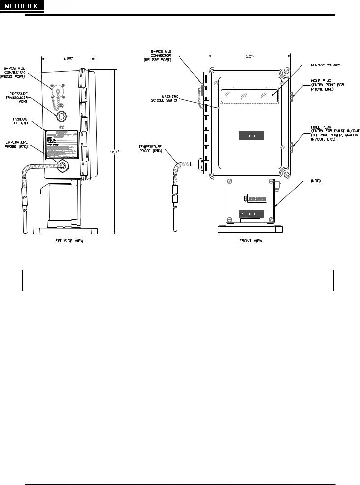
Figure 1-1 MTEK6000 exterior view
January 2002 |
1 - 3 |
MTEK6000 SERIES USER'S MANUAL
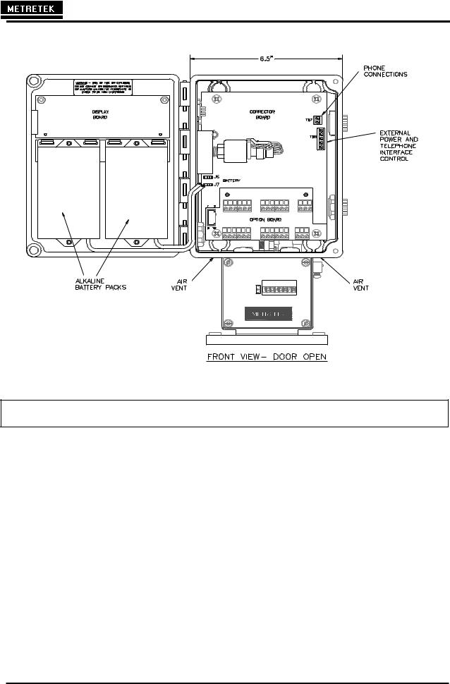
Figure 1-2 MTEK6000 interior view
1 - 4 |
January 2002 |
MTEK6000 SERIES USER'S MANUAL
Chapter 2: Installation
UNPACKING
1.Thoroughly examine the box to verify it was not damaged in shipping. If you find damage, immediately file a claim with the shipper.
2.Carefully unpack the MTEK6000 from the shipping container. Verify that the box contains every item listed on the shipping order.
INITIAL CHECK OUT
!!! CAUTION !!!
This unit contains certain electronic components that are sensitive to electrostatic discharge (ESD); therefore, proper precautions should be taken during maintenance operations to avoid ESD. It is recommended that the operator first touch the shell of the MS connector (RS-232C port) on the left side of the unit to dissipate any accumulated static charge. Additional precautions may be taken in order to minimize the possibility of ESD, including the use of a grounding wrist strap (i.e., 3M part number 2214).
3.Examine the label on the left side of the enclosure. It indicates the serial number and pressure range for your unit. Verify that these parameters match your requirements. If they do not, please contact your sales representative.
4.Open the front door by loosening the upper and lower right hand corner screws or quick release latches of the enclosure and swinging the door out. See Fig. 1-1.
5.If the unit is battery powered, verify that jumpers JP 19, 20 and 24 are in the A to B position. Load the battery pack with fresh batteries and connect it to the corrector at position J6. Repeat with the second battery pack connecting it at position J7 (see Fig. 2-1). Go to step 7.
Figure 2- 1 Power connection and configuration
6.If the unit is powered via an external power source (UPS or SPS option), make sure that jumpers JP 19, 20 and 24 are in the B to C position and connect the DC power input to the DC input screw terminals 6 (V+) and 5 (GND) prior to power up. Refer to Fig. 2-1 for locating the connection points
WARNING
The operating voltage range from an external power source is 7-18 VDC. Do NOT exceed recommended input voltage of 18 VDC.
7.When you first apply power, the display will show the first two capital letters of the first label, followed by the value and then the units. For example, the label Corrected Volume MCF with a value of 00000000 would be displayed as CV 00000000 MCF.
January 2002 |
2-1 |

MTEK6000 SERIES USER'S MANUAL
NOTE
The flashing LCD display indicates an alarm condition (e.g. First Time Power). See Chapter 3 for information on alarms.
8.You can now view selected parameter values on the display by using the scroll switch. The scroll switch is activated by the use of a magnet (one is shipped with the unit). See Display Mode, in Chapter 3, for information about this function.
POWER FOR THE MTEK6000
Two 4.5V alkaline battery packs (part # 1011-0035C-001) supply operating power to the device for approximately two years of typical operation. Recommended operating temperature range for the MTEK6000 when powered with these packs is –4 F (-20 C) to 130 F (54 C). If this supply should fail, an on-board back-up battery will maintain the unit's memory and real time clock. Backup power can maintain history data for up to seven years. When back-up power is used, the unit discontinues normal operation until the main battery pack is replaced.
Note that only one power source powers the MTEK6000; connection of battery packs to a unit configured for external power does not provide an additional source of backup power for the unit.
Optional Power Supplies
Several optional supplies are available:
A.Two Single-D Lithium battery packs - (part # 1011-0039B-001) provides an approximate life expectancy of two years over the temperature range -220 F (-300 C) to 1580 F (70 0 C). Each 3.6V, 13.0 AH battery pack can be used individually (~ 1yr life) or as a pair.
B.MTEK6000 UPS power supply - an uninterruptible 12 VDC power supply with battery back up.
C.SPS 50 solar system - 10 to 64 W systems available with battery backup; while selected system size depends on geographic location, degree of sun exposure, equipment power consumption, and site obstructions, most MTEK6000 applications only require a 10W system.
MOUNTING THE INSTRUMENT ON THE METER
1.Check the meter's rotation direction. Standard setup is clockwise rotation of the meter output shaft, as viewed from the top. The rotation of the unit can be changed to counterclockwise. Also, the input drive value for the unit can be changed.
2.Align the instrument's index base plate holes with the corresponding holes in the meter's index base plate. Secure the unit by bolting it to the meter. Ensure that the drive dogs are correctly aligned and not binding.
3.Plug all unused holes in the index base plate with the caps provided in the accessory package.
2-2 |
January 2002 |
MTEK6000 SERIES USER'S MANUAL
SETTING UP THE INDEX ASSEMBLY
Output Shaft Rotation
To change the rotation of the output shaft to counterclockwise (figure 2-2):
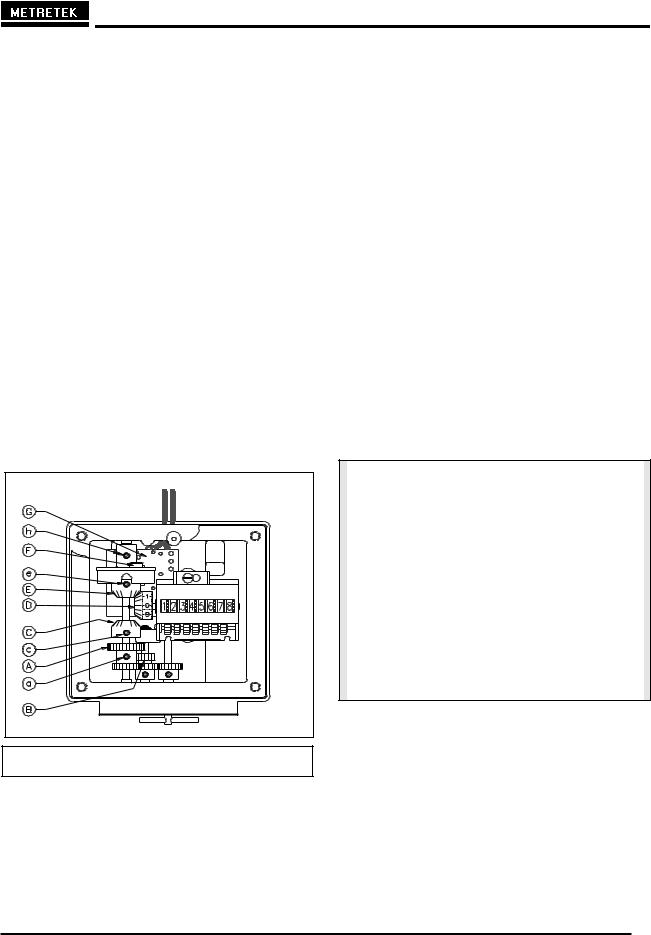
1.Loosen set screw e on gear E.
2.Disengage gear E from counter gear D.
3.Tighten set screw e.
4.Loosen set screw c on gear C.
5.Engage gear C with counter gear D.
6.Tighten set crew c.
7.Take care to align the gears properly, and verify that they turn freely and do not bind.
Figure 2- 2 Index Box Assembly
Input Drive Value
Fig. 2-2 above shows gearing in the correct position for 10, 100, 1,000 or 10,000 cubic
feet/revolution (ft3/rev) and 0.1, 1 and 10 cubic meters/revolution (m3/rev). To change the input drive value to 5 ft3/rev:
1.Loosen set screw a on compound gear A.
2.Lower gear A until its upper teeth engage the upper teeth of compound gear B.
3.Tighten set screw a.
4.Take care to align the gears properly, and verify that they turn freely and do not bind.
When changing a MTEK6000 in the field from a 10, 100, 1,000 or 10,000 ft3/rev drive meter with a 5 ft3/rev drive, the CF per Pulse In or Meter Drive parameter, must be changed to a value of 10 using software or the optional, external keypad / display.
NOTE
Electronic parameter CF per Pulse In or Meter Drive should always equal the meter drive value EXCEPT for 5 ft3/rev meters which should be set at 10. When switching to 5 ft3/rev, the gear ratio is adjusted so that two revolutions of the input drive gear result in one revolution of the magnet and hub assembly, which sends a pulse signal to the instrument that equals 10 ft3/rev. The value can be changed using software or the optional, external keypad / display (see Appendix A for addressing).
To change the input drive value to 10, 100, 1,000 or 10,000 ft3/rev, return compound gear A to its original, factory-set position. Change the CF Per Pulse In or Meter Drive parameter using software or the optional, external keypad / display (see Appendix A for addressing).
January 2002 |
2-3 |
MTEK6000 SERIES USER'S MANUAL
NOTE
When you have changed the input drive The index box assembly contains a reed value, be sure tocorrespondingmove the existing drive switch ( ) and a magnet ( ). value labelG from the window and replaceF it The magnet should be positioned so there is with a new label that states the current input 0.07" - 0.1" clearance between the magnet and drive value. For your convenience, switch. To adjust this clearance, refer to Fig. Metretek, Inc. supplies extra labels with the
1-3 on page 9 and do the following: MTEK6000 EFC.
Magnet Sensor Adjustment
The index box assembly contains a reed switch
(G) and a corresponding magnet (F). The magnet should be positioned so there is 0.07”-0.01” clearance between the magnet and switch (1.78mm-0.25mm). To adjust, refer to Figure 2-2 and do the following:
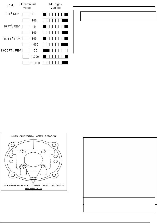
Figure 2- 3 Base Plate Showing Unit &
Index Rotation
UNIT AND INDEX ROTATION
In general, the label side of the index base plate (front) should face the front of the meter. This allows the MTEK6000 EFC to also face the front of the meter. In certain applications, the MTEK6000 EFC and index can be installed 1800 from the standard position so that viewing of the MTEK6000 EFC is acceptable. To rotate the unit and index, refer to Fig. 2-3 and do the following:
1. Remove the 4 bolts at location A.
1.Loosen set screw h.
2.Move the magnet until clearance is correct.
3.Retighten set screw h.
4. Verify the clearance is still correct. If not, repeat the procedure.
2.Rotate the base plate 1800 clockwise so that the front label side is now facing the rear of the unit.
3.Insert the 4 bolts into location B with the two lockwashers as shown. Fig. 2-3 shows the index orientation after the rotation is completed. (DO NOT OVERTIGHTEN).
COUNTER MASKING
Figure 2- 4 Uncorrected Counter Masking for Eight Digit Counter
2-4 |
January 2002 |

MTEK6000 SERIES USER'S MANUAL
PULSE INPUT TO THE MTEK6000
Magnetically operated reed switches inside the meter drive assembly send electronic pulses as the drive turns. These pulses represent uncorrected meter volume to the instrument.
To eliminate false counts that can result from the reed switch "bounce”, the MTEK6000 uses a set/reset, dual-reed switch configuration. An input pulse is generated only when the opening and closing of the first switch is followed by the opening and closing of the second switch. The main counter input is also monitored for fault conditions. When enabled, if any of the dualreed switches should be defective, the input pulses will automatically switch to the working counter input and the MTEK6000 will generate a Faulty Counter alarm. This function is enabled if the Counter Fault Monitoring parameter is set to 1 and disabled if set to 0. The default value is 0 for disable. See Appendix A for addressing.
For units supplied with indexes, the main counter input is terminated at the UNIT (BLK) MTA connector and the uncorrected pulse wiring at the FIELD (WHT) MTA connector at the lower right hand corner of the corrector printed circuit assembly. Metretek, Inc. can supply a remote index similar to the main index or a sandwich pulser for wall or pipe mount installations.
When the sandwich or external pulser option (1, 10, 20, or 50 pulse per revolution) is supplied, connect the N.O., COM, and N.C. wiring to terminals 32 (SET1), 33 (GND) and 34 (RST1) respectively.
The pulse input is software selectable for Form C (three-wire) or Form A (two-wire) connection.
Software is used to configure the pulse input. The optional, external keypad / display can also be used to configure the pulse input and other parameters. See Appendix A for addressing.
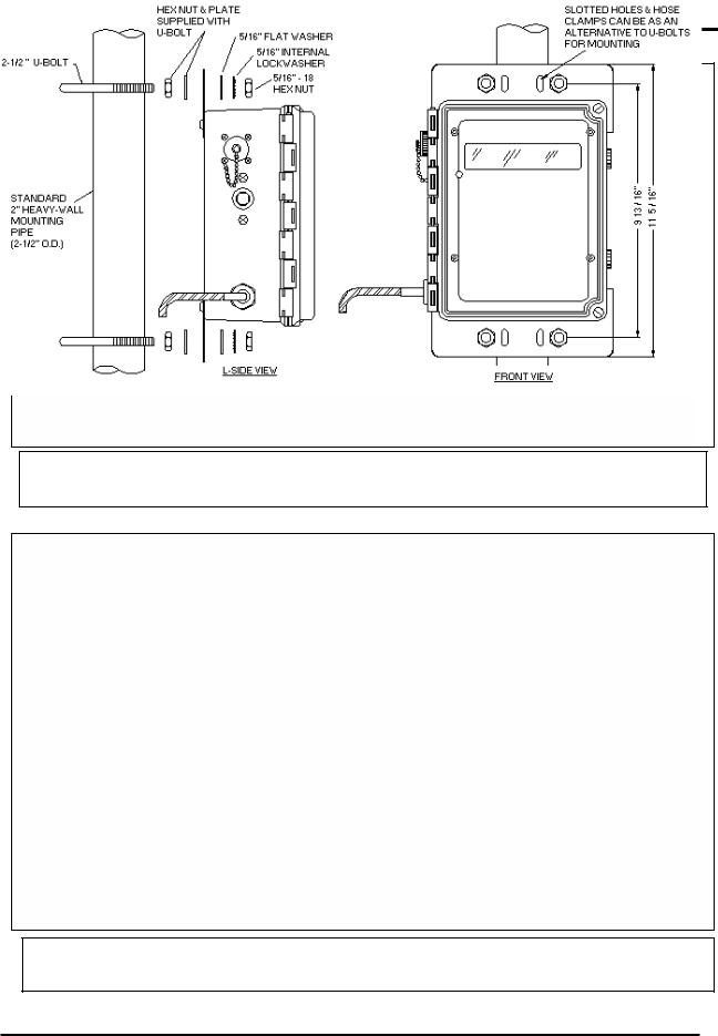
WALL AND PIPE MOUNTING
The MTEK6000 can also mount directly on a wall or on a pipe. Mounting feet are provided for wall mounting. See Figure 2-5.
For pipe mounting, approximately 10 feet of 2-inch rigid iron pipe or conduit is required. The pipe should be installed 18 to 24 inches in the ground in 6 inches wide concrete. The length of the 2-inch mounting pipe or conduit will vary according to the site, but typical installations place the MTEK6000 at about eye level for ease of operation. Mounting plates are provided for pipe mounting. Secure the MTEK6000 to the pipe with the provided U-bolts, washers and hex nuts. See
Figure 2-6.
January 2002 |
2-5 |
MTEK6000 SERIES USER'S MANUAL
Figure 2- 5 Wall Mounting
Figure 2- 4 Pipe Mounting
2-6 |
January 2002 |
MTEK6000 SERIES USER'S MANUAL
TRANSDUCERS IN THE MTEK6000
The MTEK6000 uses a precision strain gauge pressure transducer mounted inside the unit, combining maximum accuracy with low power consumption. To sense gas temperature, the MTEK6000 employs a highly linear and stable device, a platinum resistive temperature detector (RTD). Case temperature sensing is accomplished with an on-board precision reference integrated circuit (IC).
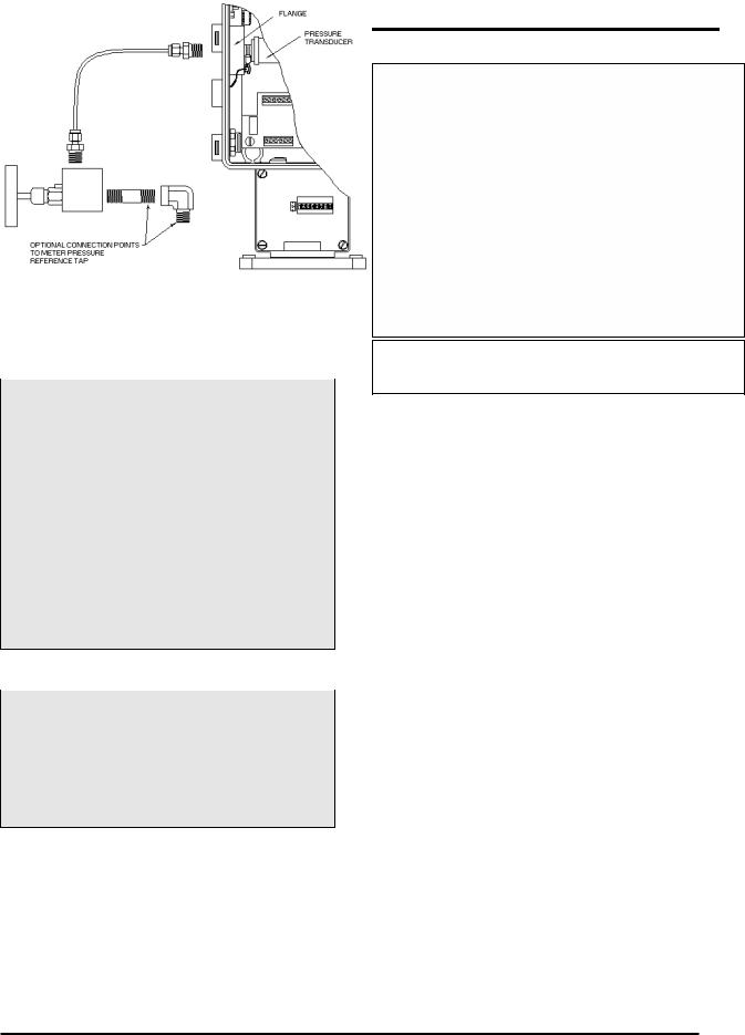
CONNECTING THE PRESSURE TUBING
WARNING
You must DEPRESSURIZE THE METER and its associated piping before you make pressure piping connections. FAILURE to do so may result in EXPLOSION and FIRE, causing SERIOUS PERSONAL INJURY and PROPERTY DAMAGE.
Do NOT attempt to connect any piping or fittings to a meter or pipe under pressure.
Do NOT SMOKE while connecting gas or test pressure to the meter.
Note
Federal Standard 192.02 requires a shut-off valve between the pressure source and the instrument. A needle valve is supplied with the optional pressure piping kit for this purpose. Its rating is 1,500 PSIG MAOP.
Figure 2- 5 Pressure Connections
As a minimum requirement, connect the pressure tubing as shown in Fig. 2-7. An optional pressure tubing connection kit (part # 2019-0009B-001) can be shipped with each instrument. Fig. 2-8 is the recommended pressure installation for ease of operation. Additional piping and valve are required for the installation and are not supplied. Use Teflon tape or pipe seal compound on all threaded connections. The tubing supplied in the kit may be longer than you need for your installation. You can cut or coil the tubing, but do not make any sharp bends in it (minimum radius is 3/4"). Tighten all the connections and perform a leak test once the meter and instrument are pressurized.
January 2002 |
2-7 |
MTEK6000 SERIES USER'S MANUAL
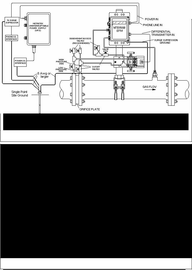
Figure 2- 7 Typical Installation for MTEK6000 EFC
Figure 2- 6 Typical Installation for MTEK6000 EFM
2-8 |
January 2002 |
MTEK6000 SERIES USER'S MANUAL
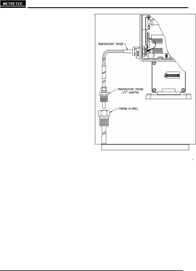
INSTALLING THE THERMAL PROBE
A thermal (temperature) probe is connected to the MTEK6000 by a 6-foot (2-meter) cable. You should coil excess cable to prevent possible damage. The probe is designed to fit into standard Metretek, Inc. thermowells. Optional 15-foot (4.5 meter) and 30-foot (9-meter) cables are available. See Fig 2-10.
To install the thermal probe, use the supplied temperature probe adapter. Refer to Table 2-1. Insert the probe into the thermowell and tighten the securing nut FINGER TIGHT only. The standard adapter is a ½” fitting. Users retrofitting instruments requiring the 5/8” adapter can order the adapter from Metretek, Inc.
Oil or ethylene glycol (antifreeze) should be used to improve heat transfer from the thermowell to the thermal probe. Be aware, however, that it is possible to cause hydraulic crushing of the probe. This can happen when there is little or no air in the thermowell above the probe. When the probe is fastened by tightening the securing nut, the space in the well decreases as the probe enters. As a result, hydraulic pressure may rise high enough to cause damage. If you use oil or antifreeze, make sure there is enough air in the thermowell above the fluid to prevent crushing the probe.
It is recommended that the thermowell be installed in the meter outlet pipe one or two diameters from the meter outlet. The insertion length of the thermowell must be sufficient to extend at least to the pipe center, but no further than 75% of the pipe’s diameter. Thermowells should not be situated where they will be exposed to direct sunlight. A sunshield should be used for installations where this cannot be avoided.
Figure 2- 8 Temperature Probe Connection
Table 2-1: |
Thermowell |
Part Numbers |
|
|
|
|
|
Pipe Size |
Insertion |
Thermowell |
|
|
Length |
Part Number |
|
|
|
|
|
4 in. |
2 ½ in. |
5340-0373 ½” NPT |
|
|
|
5340-0377 ¾” NPT |
|
|
|
5340-0384 1” NPT |
|
|
|
|
|
6 in. |
4 ½ in. |
5340-0372 ½” NPT |
|
8 in. |
|
5340-0376 ¾” NPT |
|
|
|
5340-0383 1” NPT |
|
|
|
|
|
12 in. |
7 ½ in. |
5340-0371 ½” NPT |
|
14 in. |
|
5340-0375 ¾” NPT |
|
|
|
5340-0379 |
1” NPT |
|
|
|
|
16 in. |
10 ½ in. |
5340-0370 |
½” NPT |
20 in. |
|
5340-0374 |
¾” NPT |
|
|
5340-0378 |
1” NPT |
|
|
|
|
January 2002 |
2-9 |
MTEK6000 SERIES USER'S MANUAL
INSTALLING THE PULSE OUTPUT WIRING
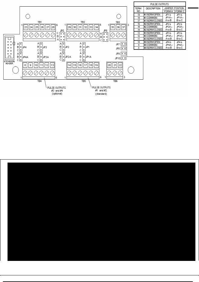
The MTEK6000 comes standard with a board installed that provides two optically isolated pulse outputs. These outputs are configurable as either Form C or Form A type outputs. An alternative version of the board is available that provides four pulse outputs. Both versions of the board also provide terminal block positions to access the uncorrected mechanical volume switch output of the index. See Fig. 2-11 for pulse output wiring. The option boards optical coupling and physical arrangement of circuitry provide a minimum of 1,500 volts of isolation.
Wiring connections for the pulse outputs are made from terminals 19 to 17 for Pulse output #1, terminals 16 to 14 for Pulse output #2, terminals 13 to 11 for Pulse output #3 and terminals 10 to 8 for Pulse output #4. See Fig. 2-11 for pulse output wiring location and Form C vs. Form A jumpering. Note that proper operation of the Form C pulse output
configuration requires that a constant wetting current be available at both the normally open and normally closed terminals by the device attached to that pulse output.
The corrected volume pulse output generated can be scaled to any desired volume value. Typical values are 10, 100, 1,000, or 10,000 cubic feet per pulse, or the metric equivalents. The scaling factor is selected by the Pulse Out CF Per Pulse parameters. The pulse duration (width) is also configurable up to 5,000 ms. The Pulse Output On-Time and Off-Time parameters determine the pulse time for corrected volume, uncorrected volume and pressure corrected volume pulses. The Alarm Pulse Time (ms) parameter determines the pulse time for alarm outputs. See Appendix C in this manual or Meter Reader Help screen for description of this parameter.
Figure 2- 9 Pulse Output Wiring
2-10 |
January 2002 |
MTEK6000 SERIES USER'S MANUAL
Volume and Alarm Pulse Specifications
1.All pulse outputs are isolated from ground and each other. Provides 1,500 volts between input and output and between contact sets.
2.Form C: DC load only, 125mWdc max, 50Vdc max
Form A: AC or DC load 800mW max, 400V max., 100mA max, continuous
3.Configurable pulse width from 1 to 5,000 milliseconds (ms).
Uncorrected Mechanical Pulse Output (Units with a Metretek Index)
The uncorrected mechanical pulse output is derived from the Form C reed switch in the index assembly. As the magnet in the drive's assembly rotates past the Form C switch, a single uncorrected volume pulse output is generated. Volume per pulse is determined by the drive rate. Each uncorrected volume pulse is equal to the gas flow for one shaft revolution.
The pulse output can be wired as a Form A or Form C switch output. Use terminals 25 (normally open), 24 (common) and 23 (normally closed) for Form C output. To wire as Form A, use terminals 25 (normally open) and 24 (common) and make no connection to terminal 23 (normally closed). The duration (width) of each pulse is equal to the length of time the reed switch is in its closed position (depends on the rate of the meter). No configuration is necessary to enable the uncorrected mechanical pulse output.
Uncorrected Pulse Output Specifications
1.3W contact rating (power dissipation).
2.Maximum switching voltage up to 30V.
3.Maximum switching current up to 200mA.
4.Maximum continuous current @ 500 mA.
NOTE
All pulse outputs are disabled in the standard unit to conserve power. The Alarm pulse output is a one time pulse output signal. No other alarm pulse will be generated until the alarm is cleared and becomes active again.
January 2002 |
2-11 |

MTEK6000 SERIES USER'S MANUAL
COMMUNICATIONS
To communicate with the MTEK6000, the Site ID (RUID) in the device must be the same as the Site ID entered in the software package. The Site ID is a unique identification number (1 to 65,535) that allows the Metretek, Inc. software packages to communicate with the MTEK6000. The default Site ID number is 1. Software can be used to enter a number other than the default. Refer to the respective software User’s Manual for additional information on these and other functions. The optional external display and keypad can also be used to change the Site ID from its default value.
RS-232C Serial (Direct) Communications
(9600 Baud)
In its standard configuration, the MTEK6000 is equipped with one RS-232C serial port. An optional RS-232C serial cable (Part # 1002-0235C-001) is required for direct communications. The serial port allows an operator to configure and collect data with an industry-standard (IBM , Compaq , etc.) portable computer (software is required for this function). The MTEK6000 communicates at 9600 baud with portable or host computers connected directly to the serial port. When communicating with the MTEK6000, Busy will be displayed on the display. Table 2-2 shows the diagnostic features of the Activity indicator when the cable is connected.
WARNING
The MTEK6000 will not go to sleep if the RS-232C serial cable is left connected and battery life will be affected drastically.
Modem Communications (2400 Baud)
NOTE
This modem complies with Part 68 of the FCC Rules. See Appendix E for details.
The internal Hayes compatible modem offers automatic answering and dialing. The modem communicates at 2400/1200/300 baud. The modem by itself can only be used in areas classified as non-hazardous or Class I, Division 2. To maintain the MTEK6000’s intrinsic safety classification in more hazardous areas such as Class I, Division 1, an optional Phone Line Interface (PLI) must be used. This device removes the high voltage ring-detect circuitry from the device and brings low-level signals into the hazardous area through intrinsic safety barriers.
Connecting the Telephone Line
If the MTEK6000 is situated in a nonhazardous or Class I, Division 2 area, connect the tip and ring wires from the telephone company's terminal box to the TIP and RING terminals (1 and 2 respectively).
If it is installed in a Class I, Division 1, Group D area, install the unit per the reference drawing shown Appendix E. Also see Appendix D for proper jumper settings.
Installation of the phone line surge protection device provided with the MTEK6000 is strongly recommended when the MTEK6000s internal modem is connected to a telephone line. The device is a separate gas tube type phone line surge suppressor and is housed in its own enclosure suitable for mounting directly to a telephone pole or other structure.
2-12 |
January 2002 |

MTEK6000 SERIES USER'S MANUAL
Table 2-2 Activity Indicator
MTEK6000 Function (RS232 cable connected) |
Activity Indicator |
|
|
RS-232C cable connected |
1 long blink |
|
|
Set #1 Pulse received |
1 short blink |
|
|
Reset #1 Pulse received |
2 short blinks |
Set #2 Pulse received |
3 short blinks |
Reset #2 Pulse received |
4 short blinks |
|
|
RS-232C cable disconnected |
3 long blinks after a few seconds delay |
|
|
January 2002 |
2-13 |

MTEK6000 SERIES USER'S MANUAL
Figure 2- 10 Corrector Board connection and jumper configuration diagram
2-14 |
January 2002 |

MTEK6000 SERIES USER'S MANUAL
GROUNDING
The information presented here is merely a guideline to help customers avoid surge damage to the MTEK6000. None of these guidelines are to be construed as replacing or superseding rules and practices defined by the National Electrical Code (NEC), or the Classification of
Gas Utility Areas for Electrical Installations guidelines, as published by the American Gas Association (AGA) or other regulatory agency.
A sound understanding of Federal, State and Local laws is fundamental to proper and legal installation work.
The MTEK6000 is configured so that the majority of the internal metal components within the device are connected (common) to the gas pipeline / meter to which the instrument is attached. Additionally, a large surge bypass MOV device has been provided inside the MTEK6000 that provides an alternate path (rather than through the correctors electronics!) for surge current to flow. One side of this device connects to the pipe through the index & meter. The other side is brought out through the enclosure to an external copper grounding lug. The separation of these two points allows for the existence of cathodic protection voltage levels on the pipe (typically about 1 volt below the surrounding soil) while still providing a path for surge current to safely bridge these points, find earth ground, and not damage the instrument.
If the MTEK6000 is to be connected to a telephone line (either on-board or through a PLI mounted in a safe area) or connected to a UPS (AC power supply), then the external ground lug provided on the MTEK6000 should be connected to earth ground. If the unit is not making connection to the phone co. lines, power co. lines, or other external equipment, then connecting the unit to an earth ground simply introduces a path for surges that otherwise would not exist. In this
case it is of no benefit to earth ground the MTEK6000’s external lug.
When the external ground lug of the MTEK6000 is to be used, it should be connected to a common ground rod (or "bed" of grounding equipment) to which is securely tied all other equipment chassis, metal cabinets, and intrinsic ground brackets. Solid copper ground wire or ground strapping of an approved size and type must be used to tie this equipment to the rod. If possible, it is far preferable that all external equipment be tied to a single site ground, that the distance between the MTEK6000 and external equipment is kept at a minimum (less than 20 feet is best), and the ground rod be located no farther than halfway between the MTEK6000 and the other equipment.
If separate site grounds must be used, as when the MTEK6000 and UPS are separated by a distance greater than 20 feet, Metretek can provide an optional device, the SPM (Surge Protection Module). A pair of SPMs can properly protect both devices in this circumstance. Control drawings detailing proper wiring of SPMs (including hazardous areas) are included with the SPM.
REFERENCES
•National Electrical Code (NFPA): Article 250 – Grounding
Articles 500 & 501Hazardous (Classified) Locations
Article 504 - Intrinsically Safe Systems
•The IAEI Soares' Book on Grounding (Available through the NFPA)
•PolyPhaser Corp. Catalog of Lightning / EMP & Grounding Solutions Minden, Nevada (800) 325-7170
January 2002 |
2-15 |
 Loading...