

Page 1
Default Login Details
User’s Guide
NSW Series
NSW100-10P / NSW100-28P / NSW200-28P
Nebula Cloud-Managed (PoE) Switch
LAN IP Address http://DHCP-assigned IP
or
a configured static IP
address
User name admin
Password Assigned by the NCC
when the NSW is
registered with the NCC.
or
1234
Version 1.00 Edition 1, 01/2017
Copyright © 2017 Zyxel Communications Corporation
Page 2

IMPORTANT!
READ CAREFULLY BEFORE USE.
KEEP THIS GUIDE FOR FUTURE REFERENCE.
This is a User’s Guide for a system managing a series of products. Not all products support all features.
Menushots and graphics in this book may differ slightly from what you see due to differences in release
versions or your computer operating system. Every effort has been made to ensure that the information
in this manual is accurate.
Related Documentation
•Quick Start Guide
The Quick Start Guide shows how to connect the managed device, such as the Nebula AP, gateway
or security gateway.
• Online Help
Click the help link for a description of the fields in the NSW menus.
•More Information
Go to support.zyxel.com to find other information on the NSW
.
NSW Series User’s Guide
2
Page 3

Contents Overview
Contents Overview
User’s Guide ........................................................................................................................................7
Getting to Know Your NSW .................................................................................................................... 8
Hardware Installation and Connection ............................................................................................. 13
Hardware Panels .................................................................................................................................. 17
Technical Reference ........................................................................................................................24
The Web Configurator ......................................................................................................................... 25
Status ...................................................................................................................................................... 30
Basic Setting .......................................................................................................................................... 32
VLAN ...................................................................................................................................................... 42
Maintenance ........................................................................................................................................ 49
Diagnostic ............................................................................................................................................. 57
Troubleshooting .................................................................................................................................... 59
NSW Series User’s Guide
3
Page 4

Table of Contents
Table of Contents
Contents Overview .............................................................................................................................3
Table of Contents.................................................................................................................................4
Part I: User’s Guide............................................................................................ 7
Chapter 1
Getting to Know Your NSW..................................................................................................................8
1.1 Introduction ....................................................................................................................................... 8
1.1.1 Hardware Comparison ........................................................................................................... 8
1.1.2 Management .......................................................................................................................... 8
1.2 Applications ...................................................................................................................................... 9
1.2.1 Backbone Application ........................................................................................................... 9
1.2.2 Bridging Example .................................................................................................................. 10
1.2.3 IEEE 802.1Q VLAN Application Examples ........................................................................... 11
1.3 Ways to Manage the NSW ............................................................................................................ 11
1.4 Good Habits for Managing the NSW ...........................................................................................12
Chapter 2
Hardware Installation and Connection ...........................................................................................13
2.1 Installation Scenarios ...................................................................................................................... 13
2.2 Desktop Installation Procedure .................................................................................................... 13
2.3 Mounting the NSW on a Rack ...................................................................................................... 14
2.3.1 Rack-mounted Installation Requirements .......................................................................... 14
2.3.2 Attaching the Mounting Brackets to the NSW ................................................................... 14
2.3.3 Mounting the NSW on a Rack ............................................................................................. 15
Chapter 3
Hardware Panels................................................................................................................................17
3.1 Front Panel ...................................................................................................................................... 17
3.1.1 Gigabit Ethernet Ports .......................................................................................................... 17
3.1.2 PoE .......................................................................................................................................... 18
3.1.3 Combo Port ........................................................................................................................... 18
3.1.4 Transceiver Slots .................................................................................................................... 18
3.1.5 Console Port .......................................................................................................................... 20
3.2 Rear Panel ....................................................................................................................................... 20
3.2.1 Power Connector ................................................................................................................. 21
3.3 LEDs ................................................................................................................................................ 21
NSW Series User’s Guide
4
Page 5

Table of Contents
Part II: Technical Reference........................................................................... 24
Chapter 4
The Web Configurator........................................................................................................................25
4.1 Overview ......................................................................................................................................... 25
4.2 System Login ................................................................................................................................... 25
4.3 The Status Screen .......................................................................................................................... 26
4.4 Saving Your Configuration ............................................................................................................. 27
4.5 Switch Lockout ............................................................................................................................... 28
4.6 Resetting the NSW ......................................................................................................................... 28
4.7 Logging Out of the Web Configurator .......................................................................................28
4.8 Help ................................................................................................................................................. 29
Chapter 5
Status...................................................................................................................................................30
5.1 Status ................................................................................................................................................ 30
Chapter 6
Basic Setting.......................................................................................................................................32
6.1 Overview ......................................................................................................................................... 32
6.1.1 What You Can Do ................................................................................................................. 32
6.2 System Information ...................................................................................................................... 32
6.3 IP Setup ........................................................................................................................................... 34
6.3.1 IP Setup Screen for NSW100 Series ...................................................................................... 34
6.3.2 IP Setup Screen for NSW200-28P .......................................................................................... 36
6.4 Port Setup ....................................................................................................................................... 39
6.5 DNS ................................................................................................................................................... 41
Chapter 7
VLAN....................................................................................................................................................42
7.1 Overview ......................................................................................................................................... 42
7.1.1 What You Can Do ................................................................................................................. 42
7.2 VLAN Status .................................................................................................................................... 42
7.2.1 VLAN Details ......................................................................................................................... 43
7.3 VLAN Configuration ...................................................................................................................... 44
7.4 Configure a Static VLAN .............................................................................................................. 44
7.5 Configure VLAN Port Settings ...................................................................................................... 46
Chapter 8
Maintenance......................................................................................................................................49
8.1 Overview ......................................................................................................................................... 49
8.1.1 What You Can Do ................................................................................................................. 49
8.2 The Maintenance Screen ............................................................................................................ 49
NSW Series User’s Guide
5
Page 6

Table of Contents
8.2.1 Erase Running-Configuration .............................................................................................. 50
8.2.2 In the web configurator, click the Save button in the top of the screen to make the
changes take effect. Save Configuration ............................................................................ 50
8.2.3 Reboot System ...................................................................................................................... 51
8.3 Firmware Upgrade ....................................................................................................................... 51
8.4 Restore a Configuration File ....................................................................................................... 53
8.5 Backup a Configuration File ........................................................................................................ 53
8.6 Tech-Support .................................................................................................................................. 54
8.7 Technical Reference ...................................................................................................................... 55
8.7.1 FTP Command Line ............................................................................................................... 55
8.7.2 Filename Conventions ......................................................................................................... 55
8.7.3 FTP Command Line Procedure ........................................................................................... 56
8.7.4 GUI-based FTP Clients ........................................................................................................... 56
Chapter 9
Diagnostic...........................................................................................................................................57
9.1 Overview ......................................................................................................................................... 57
9.2 Diagnostic ...................................................................................................................................... 57
Chapter 10
Troubleshooting..................................................................................................................................59
10.1 Power, Hardware Connections, and LEDs ................................................................................. 59
10.2 NSW Access and Login ................................................................................................................ 60
10.3 NSW Configuration ....................................................................................................................... 61
Appendix A Customer Support ....................................................................................................... 62
Appendix B Legal Information......................................................................................................... 68
Index...................................................................................................................................................74
NSW Series User’s Guide
6
Page 7

PART I
User’s Guide
7
Page 8

Getting to Know Your NSW
1.1 Introduction
This chapter introduces the main features and applications of the NSW. The NSW Series consists of the
following models:
• NSW100-10P
• NSW100-28P
• NSW200-28P
1.1.1 Hardware Comparison
The following is a hardware comparison table.
Table 1 The NSW Series Comparison Table
MODEL
10/100/1000Base-T
Port
10/100/1000 Mbps
(PoE) Port
Combo Port
NSW100-10P NSW100-28P NSW200-28P
Ports 1-8 Ports 1-24 Ports 1-24
Ports 1-8 Ports 1-24 Ports 1-24
CHAPTER 1
• Gigabit Ports
(Ethernet)
• Transceiver
Slots (100/1000
Mbps SFP)
Transceiver Slot
1000 Mbps/10G
(SFP+/DAC)
Console Port Default baud rate
PoE Maximum
Power
Special Brackets
for Rack-Mounting
See the Quick Start Guide for how to make hardware connections.
1.1.2 Management
The NSW needs an IP address for it to be managed over the network. The factory default IP address is
DHCP Client. To find the DHCP-assigned IP address, you must use the NCC, the ZON utility, or the console
port.
Ports 9-10 Ports 25-28 -
- - Ports 25-28
9600 bps
180W PoE power
budget
v- -
NSW Series User’s Guide
375W PoE power
-
budget
Default baud rate
115200 bps
375W PoE power
budget
8
Page 9
Chapter 1 Getting to Know Your NSW
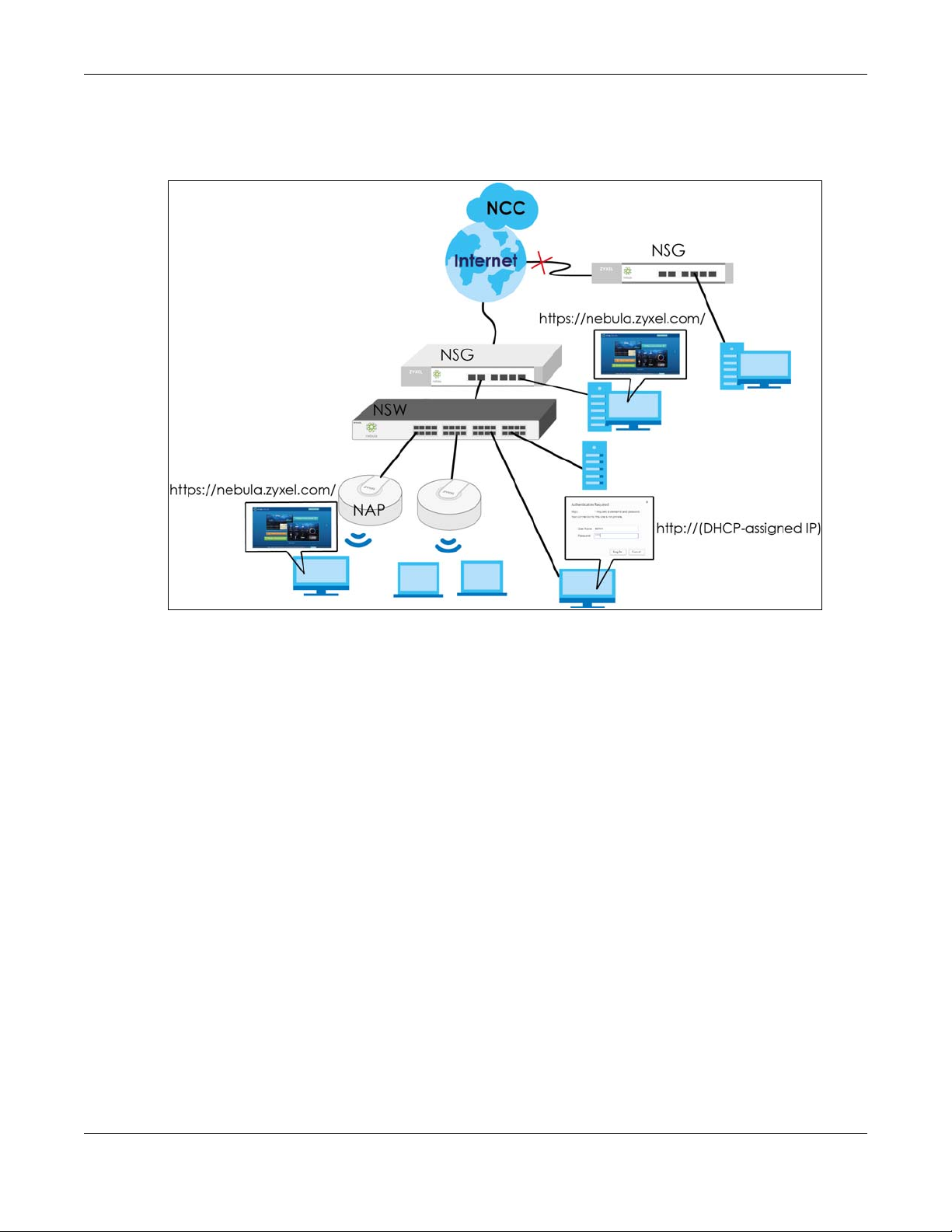
The NSW is a Nebula cloud-managed (PoE) switch. It is managed and provisioned by the NCC (Nebula
Control Center) when it is connected to the Internet and registered with the NCC.
Figure 1 NCC Management Example
You can check the system settings via the Web Configurator, the ZON (Zyxel One Network) utility and
the console port.
1.2 Applications
This section shows a few examples of using the NSW in various network environments.
1.2.1 Backbone Application
The NSW is an ideal solution for small networks where rapid growth can be expected in the near future.
The NSW can be used standalone for a group of heavy traffic users. You can connect computers and
servers directly to the NSW’s port or connect other switches to the NSW.
In this example, all computers can share high-speed applications on the server. To expand the network,
simply add more networking devices such as switches, routers, computers, print servers etc.
NSW Series User’s Guide
9
Page 10

Chapter 1 Getting to Know Your NSW
Figure 2 Backbone Application
1.2.2 Bridging Example
In this example, the NSW connects different company departments (RD and Sales) to the corporate
backbone. It can alleviate bandwidth contention and eliminate server and network bottlenecks. All
users that need high bandwidth can connect to high-speed department servers via the NSW. You can
provide a super-fast uplink connection by using a Gigabit Ethernet/mini-GBIC port on the NSW.
Moreover, the NSW eases supervision and maintenance by allowing network managers to centralize
multiple servers at a single location.
Figure 3 Bridging Application
NSW Series User’s Guide
10
Page 11

Chapter 1 Getting to Know Your NSW
1.2.3 IEEE 802.1Q VLAN Application Examples
A VLAN (Virtual Local Area Network) allows a physical network to be partitioned into multiple logical
networks. Stations on a logical network belong to one group. A station can belong to more than one
group. With VLAN, a station cannot directly talk to or hear from stations that are not in the same group(s)
unless such traffic first goes through a router.
For more information on VLANs, refer to Chapter 7 on page 42.
1.2.3.1 Tag-based VLAN Example
Ports in the same VLAN group share the same frame broadcast domain thus increase network
performance through reduced broadcast traffic. VLAN groups can be modified at any time by adding,
moving or changing ports without any re-cabling.
Shared resources such as a server can be used by all ports in the same VLAN as the server. In the
following figure only ports that need access to the server need to be part of VLAN 1. Ports can belong to
other VLAN groups too.
Figure 4 Shared Server Using VLAN Example
1.3 Ways to Manage the NSW
Use any of the following methods to manage the NSW.
• NCC. With the NCC, you can remotely manage and monitor the NSW through a cloud-based
network management system. See the NCC User’s Guide for detailed information about how to
access the NCC and manage your NSW via the NCC.
• Web Configurator. This is recommended for everyday management of the NSW using a (supported)
web browser. See Chapter 4 on page 25.
• Command Line Interface. You can use commands to see the system settings.
• FTP. Use FTP for firmware upgrades and configuration backup/restore. See Section 8.7.1 on page 55.
NSW Series User’s Guide
11
Page 12

Chapter 1 Getting to Know Your NSW
1.4 Good Habits for Managing the NSW
Do the following things regularly to make the NSW more secure and to manage the NSW more
effectively.
• Change the NSW’s password through the NCC occasionally. Use a password that’s not easy to guess
and that consists of different types of characters, such as numbers and letters.
• Write down the password and put it in a safe place.
• Back up the configuration (and make sure you know how to restore it). Restoring an earlier working
configuration may be useful if the device becomes unstable or even crashes. If you forget your
password, you will have to reset the NSW to its factory default settings. If you backed up an earlier
configuration file, you would not have to totally re-configure the NSW. You could simply restore your
last configuration.
NSW Series User’s Guide
12
Page 13

Hardware Installation and
2.1 Installation Scenarios
This chapter shows you how to install and connect the NSW.
The NSW can be placed on a desktop or rack-mounted on a standard EIA rack. Use the rubber feet in a
desktop installation and the brackets in a rack-mounted installation.
Note: For proper ventilation, allow at least 4 inches (10 cm) of clearance at the front and 3.4
inches (8 cm) at the back of the NSW. This is especially important for enclosed rack
installations.
CHAPTER 2
Connection
2.2 Desktop Installation Procedure
1 Make sure the NSW is clean and dry.
2 Set the NSW on a smooth, level surface strong enough to support the weight of the NSW and the
connected cables. Make sure there is a power outlet nearby.
3 Make sure there is enough clearance around the NSW to allow air circulation and the attachment of
cables and the power cord.
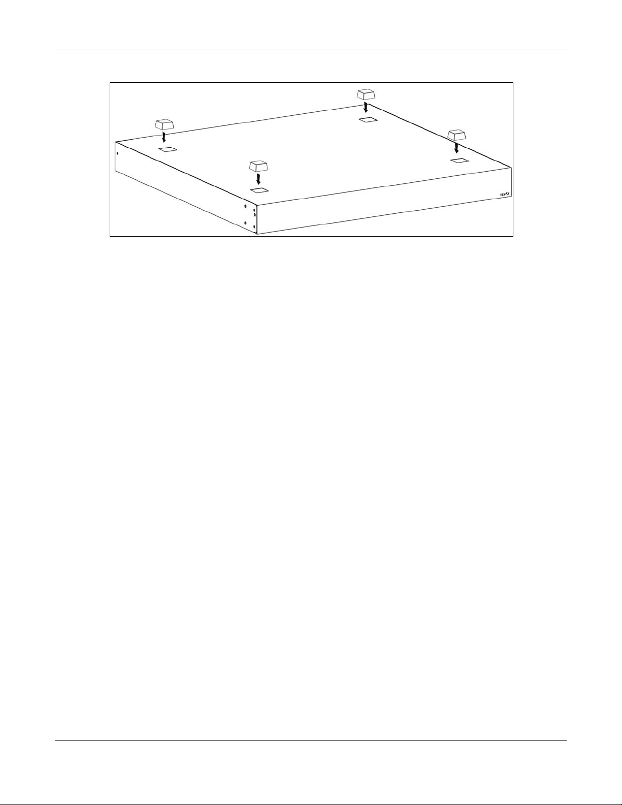
4 Remove the adhesive backing from the rubber feet.
5 Attach the rubber feet to each corner on the bottom of the NSW. These rubber feet help protect the
NSW from shock or vibration and ensure space between devices when stacking.
Note: Do NOT block the ventilation holes.
NSW Series User’s Guide
13
Page 14
Chapter 2 Hardware Installation and Connection
Figure 5 Attaching Rubber Feet
2.3 Mounting the NSW on a Rack
See Table 1 on page 8 for more information about rack-mounting brackets of each model.
The NSW can be mounted on an EIA standard size, 19-inch rack or in a wiring closet with other
equipment.
Follow the steps below to mount your NSW on a standard EIA rack using a rack-mounting kit.
2.3.1 Rack-mounted Installation Requirements
• Two mounting brackets.
• Eight M3 flat head screws and a #2 Philips screwdriver.
• Four M5 flat head screws and a #2 Philips screwdriver.
Failure to use the proper screws may damage the unit.
2.3.1.1 Precautions
• Make sure the rack will safely support the combined weight of all the equipment it contains.
• Make sure the position of the NSW does not make the rack unstable or top-heavy. Take all necessary
precautions to anchor the rack securely before installing the unit.
2.3.2 Attaching the Mounting Brackets to the NSW
1 Position a mounting bracket on one side of the NSW, lining up the four screw holes on the bracket with
the screw holes on the side of the NSW.
NSW Series User’s Guide
14
Page 15

Chapter 2 Hardware Installation and Connection
Figure 6 Attaching the Mounting Brackets (NSW100-10P)
Figure 7 Attaching the Mounting Brackets (NSW100-28P and NSW200-28P)
2 Using a #2 Philips screwdriver, install the M3 flat head screws through the mounting bracket holes into
the NSW.
3 Repeat steps 1 and 2 to install the second mounting bracket on the other side of the NSW.
4 You may now mount the NSW on a rack. Proceed to the next section.
2.3.3 Mounting the NSW on a Rack
1 Position a mounting bracket (that is already attached to the NSW) on one side of the rack, lining up the
two screw holes on the bracket with the screw holes on the side of the rack.
Figure 8 Mounting the NSW on a Rack (NSW100-10P)
NSW Series User’s Guide
15
Page 16
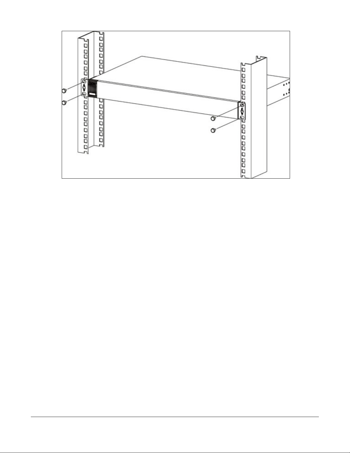
Figure 9 Mounting the NSW on a Rack (NSW100-28P and NSW200-28P)
2 Using a #2 Philips screwdriver, install the M5 flat head screws through the mounting bracket holes into
the rack.
3 Repeat steps 1 and 2 to attach the second mounting bracket on the other side of the rack.
Note: Make sure you tighten all the four screws to prevent the NSW from getting slanted.
NSW Series User’s Guide
16
Page 17
This chapter describes the front panel and rear panel of the Switch and shows you how to make the
hardware connections.
3.1 Front Panel
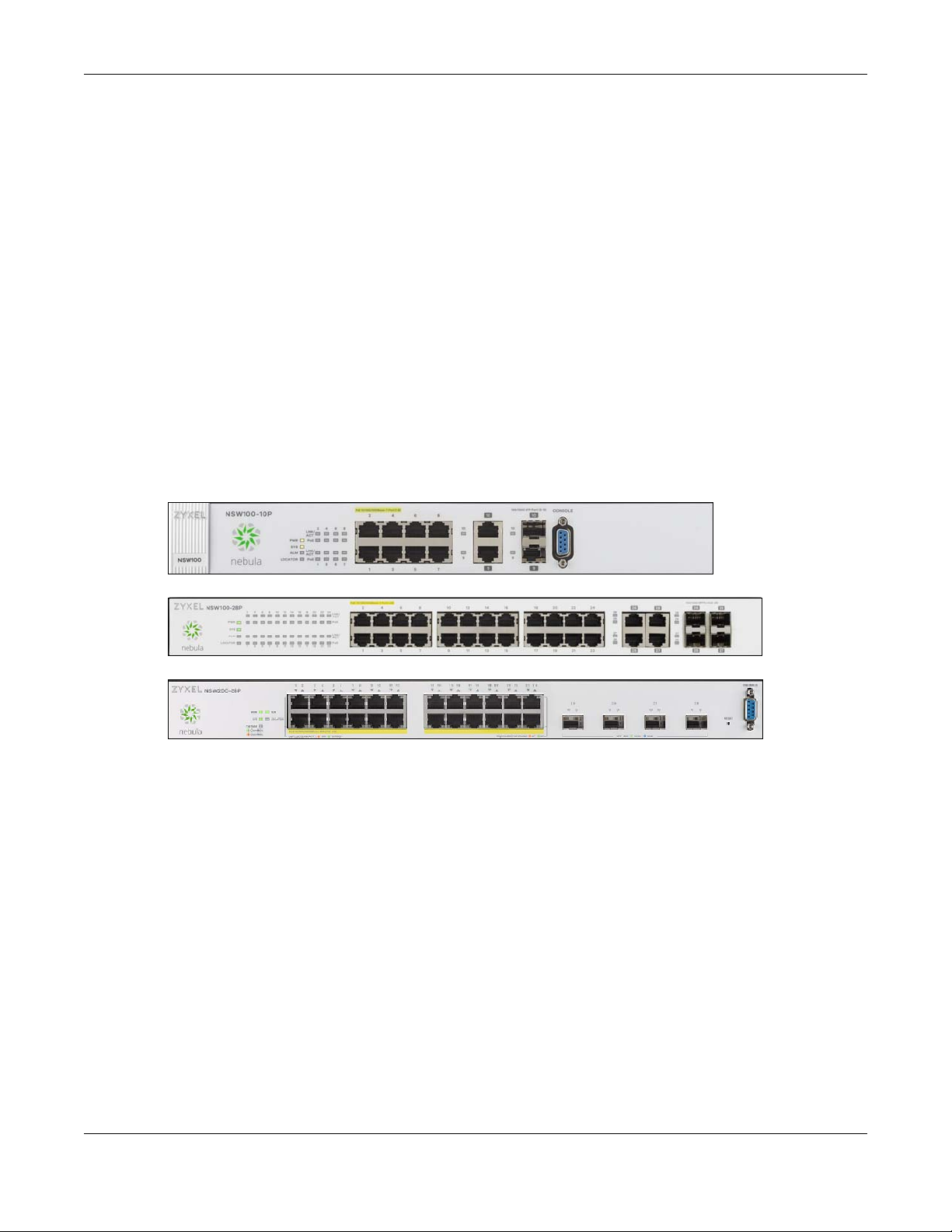
The following figures show the front panels of the NSW.
Figure 10 Front Panel: NSW100-10P
Chapter 3 Hardware Panels
CHAPTER 3
Hardware Panels
Figure 11 Front Panel: NSW100-28P
Figure 12 Front Panel: NSW200-28P
3.1.1 Gigabit Ethernet Ports
See Table 1 on page 8, for detailed information about port features of the NSW Series.
The NSW has 1000Base-T auto-negotiating, auto-crossover Ethernet ports. In 10/100/1000 Mbps Gigabit
Ethernet, the speed can be 10 Mbps, 100 Mbps or 1000 Mbps. The duplex mode can be half duplex or
full duplex.
An auto-negotiating port can detect and adjust to the optimum Ethernet speed (10/100/1000 Mbps)
and duplex mode (full duplex or half duplex) of the connected device.
An auto-crossover (auto-MDI/MDI-X) port automatically works with a straight-through or crossover
Ethernet cable.
When auto-negotiation is turned on, an Ethernet port negotiates with the peer automatically to
determine the connection speed and duplex mode. If the peer Ethernet port does not support autonegotiation or turns off this feature, the NSW determines the connection speed by detecting the signal
on the cable and using half duplex mode. When the NSW’s auto-negotiation is turned off, an Ethernet
NSW Series User’s Guide
17
Page 18
Chapter 3 Hardware Panels
port uses the pre-configured speed and duplex mode when making a connection, thus requiring you to
make sure that the settings of the peer Ethernet port are the same in order to connect.
3.1.1.1 Default Ethernet Negotiation Settings
The factory default negotiation settings for the Gigabit ports on the NSW are:
• Speed: Auto
•Duplex: Auto
• Flow control: Off
• Link Aggregation: Disabled
3.1.1.2 Auto-crossover
All ports are auto-crossover, that is auto-MDIX ports (Media Dependent Interface Crossover), so you may
use either a straight-through Ethernet cable or crossover Ethernet cable for all Gigabit port connections.
Auto-crossover ports automatically sense whether they need to function as crossover or straight ports, so
crossover cables can connect both computers and switches/hubs.
3.1.2 PoE
The NSW supports both the IEEE 802.3af Power over Ethernet (PoE) and IEEE 802.3at Power over Ethernet
(PoE) plus standards. The NSW is a Power Sourcing Equipment (PSE) because it provides a source of
power via its Ethernet ports. Each device that receives power through an Ethernet port is a Powered
Device (PD).
See Table 1 on page 8 for detailed information about PoE maximum power of each model.
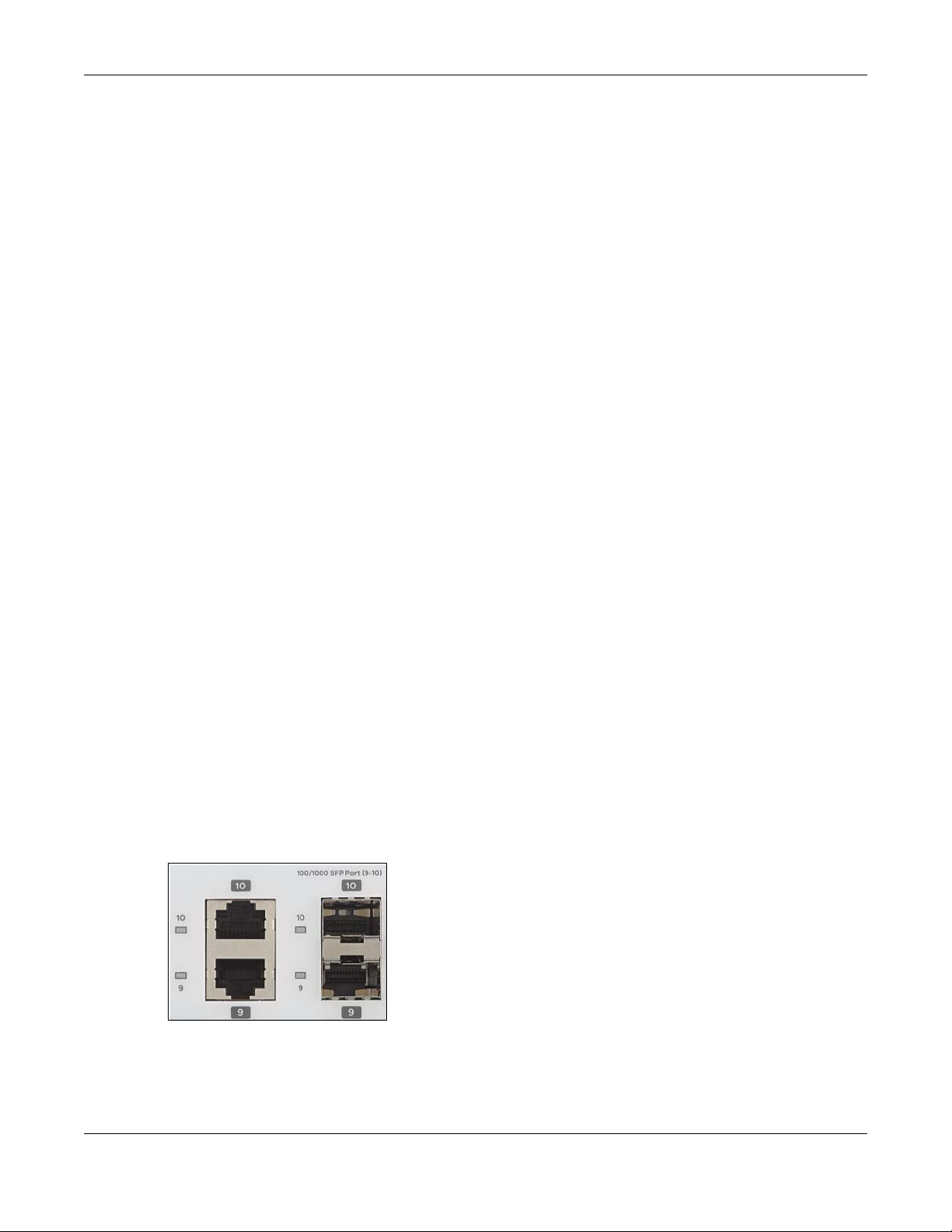
3.1.3 Combo Port
A combo port is for uplink connections. It consists of a Gigabit Ethernet port for Ethernet connection,
and a transceiver slot for fiber connection. The fiber connection takes priority if the corresponding
Gigabit port is also connected.
• 10/100/1000 Mbps Gigabit Ports - Connect these ports to high-bandwidth backbone network
Ethernet switches using 1000BASE-T compatible Category 5/5e/6 copper cables.
• Transceiver Slots - Use SFP in these slots for connections to backbone Ethernet switches.
Figure 13 Combo Port Example: Gigabit Port and Transceiver Slot
3.1.4 Transceiver Slots
See Table 1 on page 8, for detailed information about port features of the NSW Series.
NSW Series User’s Guide
18
Page 19

Chapter 3 Hardware Panels
See Section 3.1.3 on page 18, for more information about combo ports.
The transceiver slots are for Small Form-Factor Pluggable (SFP), SFP+ transceivers or DAC cable. The SFP+
(SFP Plus) and the DAC cable are enhanced versions of the SFP and support data rates of up to 10
Gbps. A transceiver is a single unit that houses a transmitter and a receiver. Use a transceiver or a DAC
cable to connect a fiber-optic cable to the NSW. The NSW does not come with transceivers nor DAC
cables. You must use transceivers or DAC cables that comply with the Small Form-factor Pluggable (SFP)
Transceiver MultiSource Agreement (MSA). See the SFF committee’s INF-8074i specification Rev 1.0 for
details.
You can change transceivers or the DAC cables while the NSW is operating. You can use different
transceivers to connect to Ethernet switches with different types of fiber-optic connectors.
• Type: SFP connection interface
Connection speed: 100/1000 Megabit per second (Mbps)
• Type: SFP+/DAC connection interface
Connection speed: 1 or 10 Gigabit per second (Gbps)
To avoid possible eye injury, do not look into an operating fiber-optic
module’s connectors.
3.1.4.1 Transceiver Installation
Use the following steps to install a mini-GBIC transceiver (SFP module).
1 Insert the transceiver into the slot with the exposed section of PCB board facing down.
2 Press the transceiver firmly until it clicks into place.
3 The NSW automatically detects the installed transceiver. Check the LEDs to verify that it is functioning
properly.
4 Close the transceiver’s latch (latch styles vary).
5 Connect the fiber optic cables to the transceiver.
Figure 14 Transceiver Installation Example
Figure 15 Connecting the Fiber Optic Cables
NSW Series User’s Guide
19
Page 20
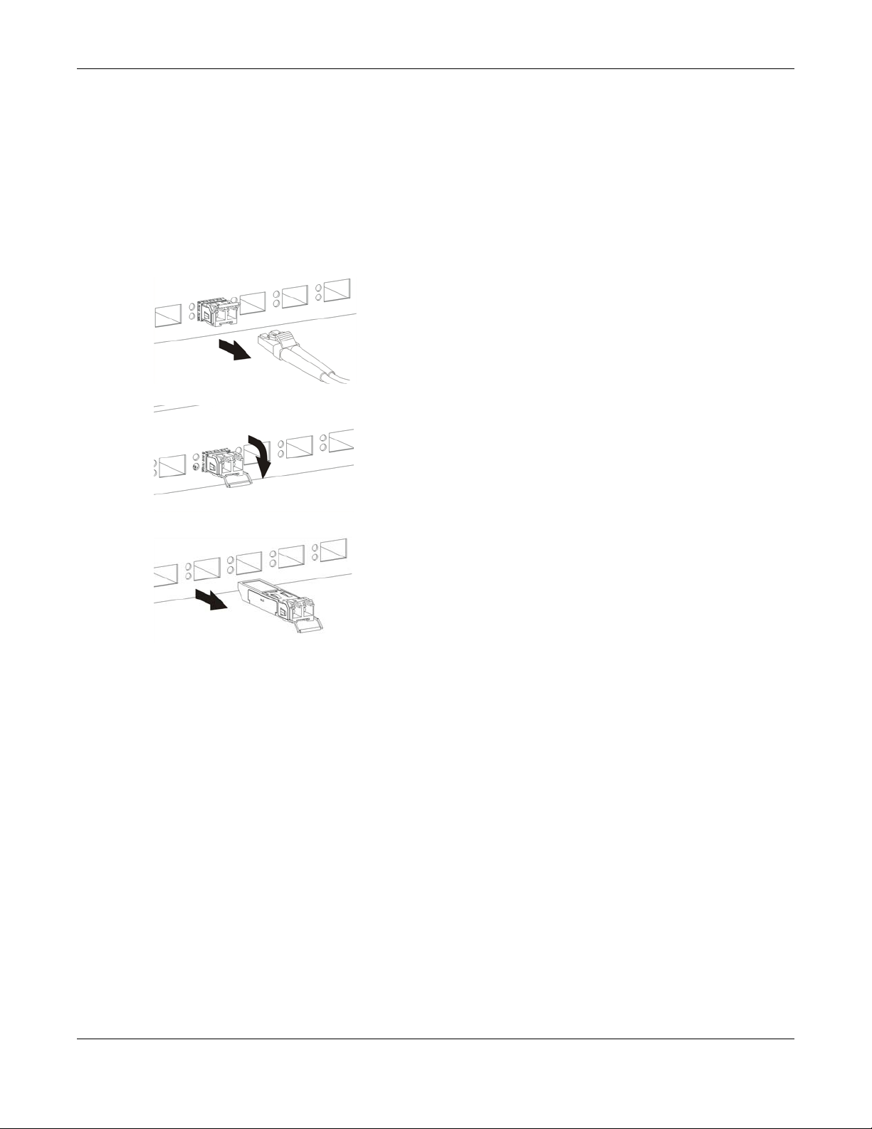
3.1.4.2 Transceiver Removal
Use the following steps to remove a mini-GBIC transceiver (SFP module).
1 Remove the fiber optic cables from the transceiver.
2 Open the transceiver’s latch (latch styles vary).
3 Pull the transceiver out of the slot.
Figure 16 Removing the Fiber Optic Cables
Figure 17 Opening the Transceiver’s Latch Example
Chapter 3 Hardware Panels
Figure 18 Transceiver Removal Example
3.1.5 Console Port
To see system settings, such as system information, VLAN status, etc., you can use a computer with
terminal emulation software configured to the following parameters:
• VT100
• Terminal emulation
• 115200 bps (NSW200-28P) or 9600 bps (NSW100-10P)
• No parity, 8 data bits, 1 stop bit
• No flow control
Connect the male 9-pin end of the console cable to the console port of the NSW. Connect the female
end to a serial port (COM1, COM2 or other COM port) of your computer.
3.2 Rear Panel
The following figures show the rear panels of the NSW.
NSW Series User’s Guide
20
Page 21
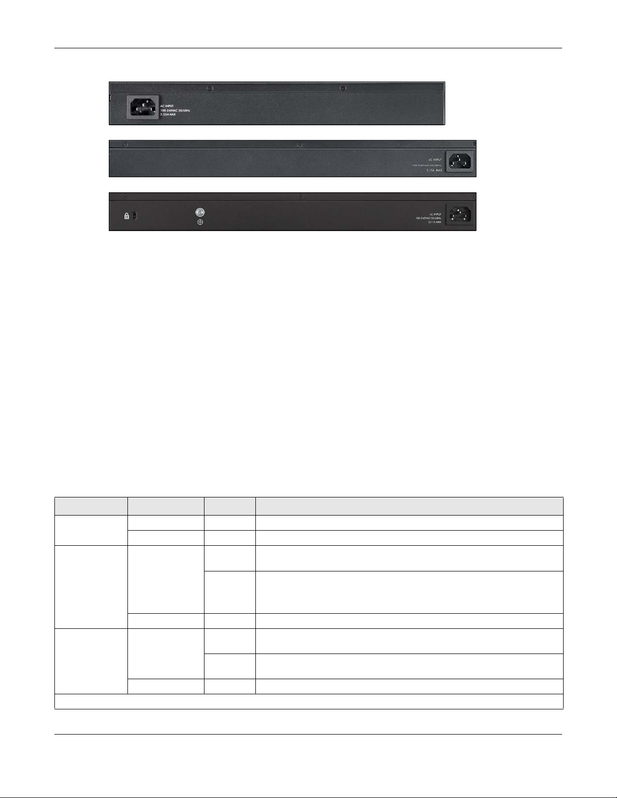
Figure 19 Rear Panel: NSW100-10P
Figure 20 Rear Panel: NSW100-28P
Figure 21 Rear Panel: NSW200-28P
3.2.1 Power Connector
Note: Make sure you are using the correct power source as shown on the panel.
To connect power to the NSW, insert the female end of the power cord to the AC power receptacle on
the rear panel. Connect the other end of the supplied power cord to a power outlet. Make sure that no
objects obstruct the airflow of the fans (located on the side of the unit).
Chapter 3 Hardware Panels
See Chapter 10 on page 59 for information on the NSW’s power supply requirements.
3.3 LEDs
After you connect the power to the NSW, view the LEDs to ensure proper functioning of the NSW and as
an aid in troubleshooting.
The following table is for NSW100 Series.
Table 2 LED Descriptions for NSW100 Series
LED COLOR STATUS DESCRIPTION
PWR Green On The system is receiving power from the power slot.
Off The system is not receiving power from the power module in the power slot.
SYS Green On The system is on and functioning properly. The NSW can connect to the
Nebula Control Center.
Blinking The system is rebooting and performing self-diagnostic tests.
If the system LED is blinking green with the alarm LED blinking red, it means the
NSW cannot connect to the Nebula Control Center.
Off The power is off or the system is not ready/malfunctioning.
ALM Red On The system is having a hardware failure, such as high device temperature,
Blinking If the alarm LED is blinking red with the system LED blinking green, it means the
Off The system is functioning normally.
10/100/1000Base-T Ports
wrong voltage, or abnormal fan speed.
NSW cannot connect to the Nebula Control Center.
NSW Series User’s Guide
21
Page 22
Chapter 3 Hardware Panels
Table 2 LED Descriptions for NSW100 Series (continued)
LED COLOR STATUS DESCRIPTION
1-8 (NSW10010P)/1-24
(NSW100-28P)
LNK/ACT
PoE 10/100/1000Base-T Ports
1-8 (NSW10010P)/1-24
(NSW100-28P)
PoE
100/1000 Mbps SFP Slots
9-10 (NSW10010P)/25-28
(NSW100-28P)
LNK/ACT
Green On The link to a 10 Mbps or a 1000 Mbps Ethernet network is up.
Blinking The system is transmitting/receiving to/from a 10 Mbps or a 1000 Mbps
Ethernet network.
Amber On The link to a 100 Mbps Ethernet network is up.
Blinking The system is transmitting/receiving to/from a 100 Mbps Ethernet network.
Off The Ethernet link is down.
Green On Power supplied to all PoE Ethernet ports meets the IEEE 802.3at standard.
Amber On Power supplied to all PoE Ethernet ports meets the IEEE 802.3af standard.
Off The PoE is off or the Ethernet link is down.
Green On The port has a successful 1000 Mbps connection.
Blinking The port is transmitting or receiving data at 1000 Mbps.
Amber On The port has a successful 100 Mbps connection.
Blinking The port is transmitting or receiving data at 100 Mbps.
Off This link is disconnected.
The following table is for NSW200-28P.
Table 3 LED Descriptions for NSW200-28P
LED COLOR STATUS DESCRIPTION
PWR Green On The system is receiving power from the power slot.
Off The system is not receiving power from the power module in the power slot.
SYS Green On The system is on and functioning properly. The NSW can connect to the
Nebula Control Center.
Blinking The system is rebooting and performing self-diagnostic tests.
If the system LED is blinking green with the alarm LED blinking red, it means the
NSW cannot connect to the Nebula Control Center.
Off The power is off or the system is not ready/malfunctioning.
FAN Green On The fan is functioning properly.
Amber On The fan is not functioning at a proper speed or malfunctioning.
PoE MAX Green On PoE power usage is over 80 percent of the power supplied budget, but
Amber On PoE power usage is more than 95 percent of the power supplied budget.
Off PoE power usage is below 80 percent of the power supplied budget.
10/100/1000Base-T Ports
1-24 LNK/ACT
(Left)
Green On The link to a 10 Mbps or a 1000 Mbps Ethernet network is up.
Blinking The system is transmitting/receiving to/from a 10 Mbps or a 1000 Mbps
Amber On The link to a 100 Mbps Ethernet network is up.
Blinking The system is transmitting/receiving to/from a 100 Mbps Ethernet network.
Off The Ethernet link is down.
below 95 percent of the power supplied budget.
Ethernet network.
NSW Series User’s Guide
22
Page 23

Chapter 3 Hardware Panels
Table 3 LED Descriptions for NSW200-28P (continued)
LED COLOR STATUS DESCRIPTION
PoE 10/100/1000Base-T Ports
1-24 PoE (Right) Green On Power supplied to all PoE Ethernet ports meets the IEEE 802.3at standard.
Amber On Power supplied to all PoE Ethernet ports meets the IEEE 802.3af standard.
Off The PoE is off or the Ethernet link is down.
1000 Mbps/10G SFP+ Slots
25-28 LNK/ACT Green On The port has a successful 1000 Mbps connection.
Blinking The port is transmitting or receiving data at 1000 Mbps.
Blue On The port has a successful 10 Gbps connection.
Blinking The port is transmitting or receiving data at 10 Gbps.
Off This link is disconnected.
NSW Series User’s Guide
23
Page 24

PART II
Technical Reference
24
Page 25

4.1 Overview
This section introduces the configuration and functions of the web configurator.
The screens are based on NSW200-28P.
The web configurator is an HTML-based management interface that allows easy NSW setup and
management via Internet browser. Use Internet Explorer 9.0 and later versions, Mozilla Firefox 21 and
later versions, Safari 6.0 and later versions or Google Chrome 26.0 and later versions. The recommended
screen resolution is 1024 by 768 pixels.
In order to use the web configurator you need to allow:
• Web browser pop-up windows from your device. Web pop-up blocking is enabled by default in
Windows XP SP (Service Pack) 2.
• JavaScript (enabled by default).
• Java permissions (enabled by default).
CHAPTER 4
The Web Configurator
4.2 System Login
1 Start your web browser.
2 The NSW is a DHCP client by default. Type “http://DHCP-assigned IP” in the Location or Address field.
Press [ENTER].
If the NSW is not connected to a DHCP server, type “http://” and the static IP address of the NSW in the
Location or Address field. Press [ENTER]. Your computer must be in the same subnet in order to access
this website address.
3 The login screen appears. The default username is admin. The associated default password is assigned
by the NCC when the NSW is registered with the NCC or 1234. The date and time display as shown if you
have not configured a time server nor manually entered a time and date in the General Setup screen.
NSW Series User’s Guide
25
Page 26

Chapter 4 The Web Configurator
A
B
CD
EF
Figure 22 Web Configurator: Login
4 Click OK to view the first web configurator screen.
4.3 The Status Screen
The Status screen is the first screen that displays after you access the web configurator.
The following figure shows the navigating components of a web configurator screen.
Figure 23 Web Configurator Home Screen for PoE model(s) (Status)
A - Click the menu items to open submenu links, and then click on a submenu link to open the screen in
the main window.
B, C, D, E, F - These are quick links which allow you to perform certain tasks no matter which screen you
are currently working in.
B - Click this link to update the information in the screen you are viewing currently.
C - Click this link to save your configuration into the NSW’s nonvolatile memory. Nonvolatile memory is
the configuration of your NSW that stays the same even if the NSW’s power is turned off.
D - Click this link to go to the status page of the NSW.
E - Click this link to log out of the web configurator.
NSW Series User’s Guide
26
Page 27

Chapter 4 The Web Configurator
F - Click this link to display web help pages. The help pages provide descriptions for each configuration
screen.
The following table describes the links in the navigation panel. The navigation panel varies depending
on the product model you use.
Table 4 Navigation Panel Links
LINK DESCRIPTION
Basic Settings
System Info This link takes you to a screen that displays general system information.
IP Setup This link takes you to a screen where you can configure the DHCP client, and a static IP address
(IP address and subnet mask).
Port Setup This link takes you to a screen where you can configure settings for individual NSW ports.
DNS
(NSW200-28P
only)
Advanced Application
VLAN This link takes you to screens where you can configure port-based or 802.1Q VLAN. You can
VLAN Status This link takes you to a screen where you can view and search all VLAN groups.
VLAN Detail This link takes you to a screen where you can view detailed port settings and status of the VLAN
Static VLAN This link takes you to a screen where you can configure and view 802.1Q VLAN parameters for
VLAN Port Setting This link takes you to a screen where you can configure the static VLAN settings on a port.
Management
Maintenance This link takes you to screens where you can perform firmware and configuration file mainte-
Firmware
Upgrade
Restore Configuration/Backup
Configuration
Tech-Support This link takes you to a screen where you can log information of CPU utilization history, memory
Diagnostic This link takes you to a screen where you can ping IP addresses, run traceroute, test port(s) and
This link takes you to a screen where you can configure DNS (domain name server) IP
addresses.
also configure a protocol based VLAN or a subnet based VLAN in these screens.
group.
the NSW.
nance as well as reboot the system.
This link takes you to a screen where you can upload firmware to your device.
This link takes you to a screen where you can backup and restore your device’s configuration
(settings) or reset the factory default setting.
and Mbuf (Memory Buffer) log, and crash reports.
show the NSW’s location.
4.4 Saving Your Configuration
When you are done modifying the settings in a screen, click Apply to save your changes back to the
run-time memory. Settings in the run-time memory are lost when the NSW’s power is turned off.
Click the Save link in the upper right hand corner of the web configurator to save your configuration to
nonvolatile memory. Nonvolatile memory refers to the NSW’s storage that remains even if the NSW’s
power is turned off.
Note: Use the Save link when you are done with a configuration session.
NSW Series User’s Guide
27
Page 28

4.5 Switch Lockout
You could block yourself (and all others) from managing the NSW if you do one of the following:
1 Delete the management VLAN (default is VLAN 1).
2 Delete all port-based VLANs with the CPU port as a member. The “CPU port” is the management port of
the NSW.
3 Filter all traffic to the CPU port.
4 Disable all ports.
5 Misconfigure the text configuration file.
6 Forget the password and/or IP address.
7 Prevent all services from accessing the NSW.
8 Change a service port number but forget it.
Chapter 4 The Web Configurator
Note: Be careful not to lock yourself and others out of the NSW.
4.6 Resetting the NSW
You can reset your NSW via the web configurator, or the reset button on the front panel according to
the NSW you’re using.
4.7 Logging Out of the Web Configurator
Click Logout in a screen to exit the web configurator. You have to log in with your password again after
you log out. This is recommended after you finish a management session for security reasons.
You also have to log in with your password again, when the NSW times out.
Figure 24 Web Configurator: Logout Screen
NSW Series User’s Guide
28
Page 29

4.8 Help
The web configurator’s online help has descriptions of individual screens and some supplementary
information.
Click the Help link from a web configurator screen to view an online help description of that screen.
Chapter 4 The Web Configurator
NSW Series User’s Guide
29
Page 30

5.1 Status
The Status screen displays when you log into the NSW or click Status at the top right corner of the web
configurator. The Status screen displays general device information, system status, and its IP addresses.
Figure 25 Status
CHAPTER 5
Status
The following table describes the labels in this screen.
Table 5 Status
LABEL DESCRIPTION
Device Information
Device Type This field displays the model name of the NSW.
Registered
Status
Boot Version This field displays the version number and date of the boot module that is currently on the NSW.
System Name This field displays the name used to identify the NSW on any network.
Firmware
Version
System Location This field displays the location configured for the NSW in the Nebula Control Center.
Serial Number This field displays the serial number of the NSW. The serial number is used for device tracking and
This field displays Registered when the NSW is registered with the Nebula Control Center and
Unregistered when it is not. You can register the NSW in Nebula Control Center (preferable) or
myZyxel.com. If you register the NSW in myZyxel.com but didn't create an organization in Nebula
Control Center yet, then you will need to register the NSW in Nebula Control Center again. An
unregistered NSW cannot be managed by Nebula Control Center.
This field displays the version number and date of the firmware the NSW is currently running.
control.
NSW Series User’s Guide
30
Page 31

Chapter 5 Status
Table 5 Status (continued)
LABEL DESCRIPTION
System Time This field displays the current date and time in the UAG. The format is mm-dd-yyyy hh:mm:ss.
MAC Address This field displays the MAC addresses of the NSW.
System Up Time This field displays how long the NSW has been running since it last restarted or was turned on.
Login Timeout This field displays how many minutes a management session can be left idle before the session
times out. After it times out you have to log in with your password again.
Detail Click this link to go to the Basic Setting > System Info screen to check other detailed information,
such as system resource usage and the NSW temperature, fan speeds or voltage.
IP Address Information
IPv4 Address This field displays the NSW’s current IPv4 address. 0.0.0.0 means no IP address is assigned.
Subnet Mask This field displays the NSW’s subnet mask. 0.0.0.0 means no subnet mask is assigned.
Default
Gateway
IP Setup Click the link to go to the Basic Setting > IP Setup screen.
Quick Links This section provides the shortcut link to a specific configuration screen.
This field displays the IP address of the NSW’s default gateway. 0.0.0.0 means no gateway is
assigned.
NSW Series User’s Guide
31
Page 32

6.1 Overview
This chapter describes how to configure the System Info, IP Setup, and Port Setup screens.
See Table 4 on page 27 for menu differences of the NSW Series.
6.1.1 What You Can Do
• Use the System Info screen (Section 6.2 on page 32) to check the firmware version number.
• Use the IP Setup screen (Section 6.3 on page 34) to configure the NSW IP address, default gateway
device, and the management VLAN ID.
• Use the Port Setup screen (Section 6.5 on page 39) to configure the NSW port settings.
• Use the DNS screen (Section 6.6 on page 41) to configure the default domain name server.
Chapter 6 Basic Setting
CHAPTER 6
Basic Setting
6.2 System Information
In the navigation panel, click Basic Setting > System Info to display the screen as shown. Use this screen
to view general system information. You can check the firmware version number.
NSW Series User’s Guide
32
Page 33

Figure 26 Basic Setting > System Info
The following table describes the labels in this screen.
Table 6 Basic Setting > System Info
LABEL DESCRIPTION
System Name This field displays the descriptive name of the NSW for identification purposes.
Product Model This field displays the product model of the NSW. Use this information when searching for firmware
upgrade or looking for other support information in the website.
ZyNOS F/W
Version
Ethernet
Address
CPU Utilization CPU utilization quantifies how busy the system is. Current (%) displays the current percentage of
Memory
Utilization
Hardware Monitor
Temperature
Unit
This field displays the version number of the NSW 's current firmware including the date created.
This field refers to the Ethernet MAC (Media Access Control) address of the NSW.
CPU utilization.
Memory utilization shows how much DRAM memory is available (Total (byte)) and in use (Used
(byte)). It also displays the current percentage of memory utilization (Utilization (%)).
The NSW has temperature sensors that are capable of detecting and reporting if the
temperature rises above the threshold. You may choose the temperature unit (Centigrade or
Fahrenheit) in this field.
NSW Series User’s Guide
33
Page 34

Chapter 6 Basic Setting
Table 6 Basic Setting > System Info (continued)
LABEL DESCRIPTION
Temperature BOARD, MAC and PHY refer to the location of the temperature sensors on the NSW printed circuit
board.
Current This shows the current temperature at this sensor.
MAX This field displays the maximum temperature measured at this sensor.
MIN This field displays the minimum temperature measured at this sensor.
Threshold This field displays the upper temperature limit at this sensor.
Status This field displays Normal for temperatures below the threshold and Error for those above.
Fan Speed
(RPM)
Current This field displays this fan's current speed in Revolutions Per Minute (RPM).
MAX This field displays this fan's maximum speed measured in Revolutions Per Minute (RPM).
MIN This field displays this fan's minimum speed measured in Revolutions Per Minute (RPM). "<41" is
Threshold This field displays the minimum speed at which a normal fan should work.
Status Normal indicates that this fan is functioning above the minimum speed. Error indicates that this
Voltage(V) The power supply for each voltage has a sensor that is capable of detecting and reporting if the
Current This is the current voltage reading.
MAX This field displays the maximum voltage measured at this point.
MIN This field displays the minimum voltage measured at this point.
Threshold This field displays the percentage tolerance of the voltage with which the NSW still works.
Status Normal indicates that the voltage is within an acceptable operating range at this point;
A properly functioning fan is an essential component (along with a sufficiently ventilated, cool
operating environment) in order for the device to stay within the temperature threshold. Each fan
has a sensor that is capable of detecting and reporting if the fan speed falls below the threshold
shown.
displayed for speeds too small to measure (under 2000 RPM).
fan is functioning below the minimum speed.
voltage falls out of the tolerance range.
otherwise Error is displayed.
6.3 IP Setup for NSW100 Series
Use the IP Setup screen to configure the NSW IP address, default gateway device, and the
management VLAN ID. The default gateway specifies the IP address of the default gateway (next hop)
for outgoing traffic.
Note: If you can access the NCC via the Internet, you may change the NSW static IP address
via the NCC.
Use this screen to manage the IP address.
NSW Series User’s Guide
34
Page 35

Chapter 6 Basic Setting
Figure 27 Basic Setting > IP Setup (NSW100 Series)
The following table describes the labels in this screen.
Table 7 Basic Setting > IP Setup (NSW100 Series)
LABEL DESCRIPTION
Default Management IP Address
DHCP Client Select this option if there is a DHCP server that can assign the NSW an IP address, subnet mask,
Static IP
Address
IP Address Enter the IP address of your NSW in dotted decimal notation.
IP Subnet
Mask
Default
Gateway
Static
Domain
Name Server
Preference 1-2Enter a domain name server IPv4 address in this field. 1 and 2 are the priority of the DNS server
VID Enter the VLAN identification number.
Add Click this to create a new entry.
a default gateway IP address and a domain name server IP address automatically.
Select this option if you don’t have a DHCP server or if you wish to assign static IP address
information to the NSW. You need to fill in the following fields when you select this option.
Enter the IP subnet mask in dotted decimal notation, for example, 255.255.255.0.
Enter the default gateway of the Zyxel device.
You can assign static domain name to its corresponding IP address. You need to fill in the
following fields.
address.
This saves your changes to the NSW’s run-time memory. The NSW loses these changes if it is
turned off or loses power, so use the Save link on the top navigation panel to save your changes
to the non-volatile memory when you are done configuring.
Cancel Click Cancel to reset the fields to your previous configuration.
Index This field displays the index number of an entry.
IP Address This field displays IP address of the NSW.
IP Subnet Mask This field displays the subnet mask of the NSW.
VID This field displays the VLAN identification number of the NSW.
Apply Click Apply to save your changes to the NSW’s run-time memory. The NSW loses these changes
if it is turned off or loses power, so use the Save link on the top navigation panel to save your
changes to the non-volatile memory when you are done configuring.
Cancel Click Cancel to reset the fields to your previous configuration.
NSW Series User’s Guide
35
Page 36
Chapter 6 Basic Setting
6.4 IP Setup for NSW200-28P
6.4.1 Management IP Address
The NSW needs an IP address for it to be managed over the network. The factory default IP address is
DHCP Client. If there is not a DHCP server to assign the NSW an IP address, then you must give the NSW a
static IP address. The subnet mask specifies the network number portion of an IP address.
Note: You must configure a VLAN first. Each VLAN can only have one management IP
address.
Figure 28 Basic Setting > IP Setup
The following table describes the labels in this screen.
Table 8 Basic Setting > IP Setup
LABEL DESCRIPTION
Index This field displays the index number of an entry.
IP Address This field displays IP address of the NSW.
IP Subnet Mask This field displays the subnet mask of the NSW.
VID This field displays the VLAN identification number of the NSW.
Type This shows whether this IP address is dynamically assigned from a DHCP server or manually
Renew Click this to renew the dynamic IP address.
Release Click this to release the dynamic IP address.
assigned (Static).
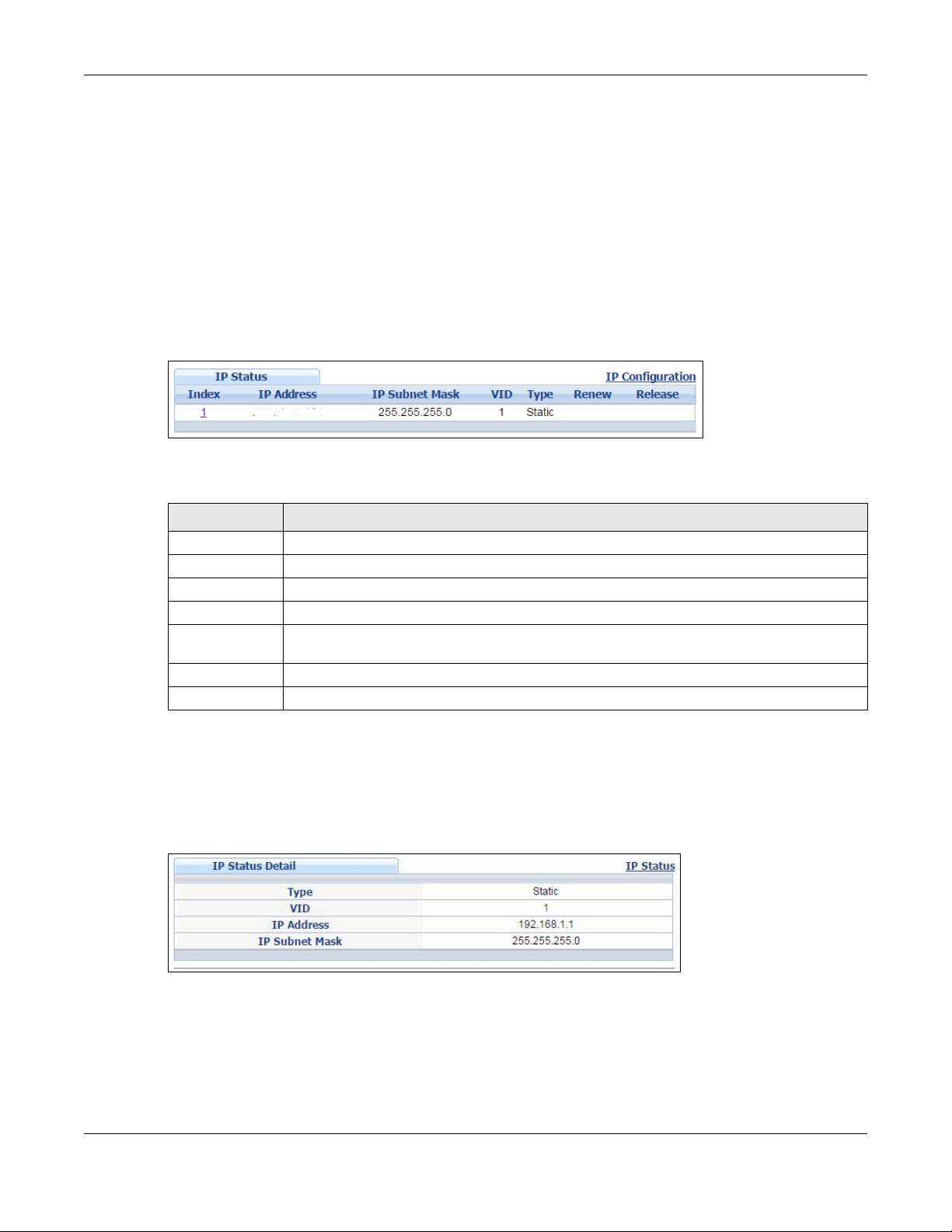
6.4.2 IP Status Details
Use this screen to view IP status details. Click a number in the Index column in the IP Status screen to
display the screen as shown next.
Figure 29 Basic Setting > IP Setup > IP Status Details: Static
NSW Series User’s Guide
36
Page 37

Chapter 6 Basic Setting
The following table describes the labels in this screen.
Table 9 Basic Setting > IP Setup > IP Status Details: Static
LABEL DESCRIPTION
Type This shows whether ths IP address is dynamically assigned from a DHCP server or manually
VID This is the VLAN identification number.
IP Address This is the IP address of your NSW in dotted decimal notation.
IP Subnet Mask This is the IP subnet mask of your NSW in dotted decimal notation for example 255.255.255.0.
assigned (Static or DHCP).
Figure 30 Basic Setting > IP Setup > IP Status Details: DHCP
The following table describes the labels in this screen.
Table 10 Basic Setting > IP Setup > IP Status Details: DHCP
LABEL DESCRIPTION
Type This shows whether this IP address is dynamically assigned from a DHCP server or manually
assigned (Static or DHCP).
VID This is the VLAN identification number.
IP Address This is the IP address of your NSW in dotted decimal notation.
IP Subnet Mask This is the IP subnet mask of your NSW in dotted decimal notation for example 255.255.255.0.
Lease Time This displays the length of time in seconds that this interface can use the current dynamic IP
Renew Time This displays the length of time from the lease start that the NSW will request to renew its current
Rebind Time This displays the length of time from the lease start that the NSW will request to get any dynamic
Lease Time Start This displays the date and time that the current dynamic IP address assignment from the DHCP
Lease Time End This displays the date and time that the current dynamic IP address assignment from the DHCP
Default
Gateway
DNS Server This displays the IP address of the primary and secondary DNS servers assigned by the DHCP
address from the DHCP server.
dynamic IP address from the DHCP server.
IP address from the DHCP server.
server began. You should configure date and time in Basic Setting > General Setup.
server will end. You should configure date and time in Basic Setting > General Setup.
This displays the IP address of the default gateway assigned by the DHCP server. 0.0.0.0 means
no gateway is assigned.
server. 0.0.0.0 means no DNS server is assigned.
NSW Series User’s Guide
37
Page 38

6.4.3 IP Configurations
Use this screen to configure the default gateway device, and manage the IP address.
Figure 31 Basic Setting > IP Setup > IP Configuration
Chapter 6 Basic Setting
The following table describes the labels in this screen.
Table 11 Basic Setting > IP Setup > IP Configuration
LABEL DESCRIPTION
Default
Gateway
Apply Click Apply to save your changes to the NSW’s run-time memory. The NSW loses these changes
Cancel Click Cancel to reset the fields to your previous configuration.
IP Interface
DHCP Client Select this option if you have a DHCP server that can assign the NSW an IP address, subnet
Static IP
Address
IP Address Enter the IP address of your NSW in dotted decimal notation.
IP Subnet
Mask
VID Enter the VLAN identification number.
Add Click this to create a new entry.
Cancel Click Cancel to reset the fields to your previous configuration.
Index This field displays the index number of an entry.
IP Address This field displays IP address of the NSW.
Type the IP address of the default outgoing gateway in dotted decimal notation, for example
192.168.1.254.
if it is turned off or loses power, so use the Save link on the top navigation panel to save your
changes to the non-volatile memory when you are done configuring.
mask, a default gateway IP address and a domain name server IP address automatically.
Select this option if you don’t have a DHCP server or if you wish to assign static IP address
information to the NSW. You need to fill in the following fields when you select this option.
Enter the IP subnet mask in dotted decimal notation, for example, 255.255.255.0.
This saves your changes to the NSW’s run-time memory. The NSW loses these changes if it is
turned off or loses power, so use the Save link on the top navigation panel to save your changes
to the non-volatile memory when you are done configuring.
NSW Series User’s Guide
38
Page 39

Table 11 Basic Setting > IP Setup > IP Configuration (continued)
LABEL DESCRIPTION
IP Subnet Mask This field displays the subnet mask of the NSW.
VID This field displays the VLAN identification number of the NSW.
Type This field displays the type of IP address status.
Delete Click Delete to remove the selected entry from the summary table.
Cancel Click Cancel to clear the check boxes.
6.5 Port Setup
Use this screen to configure the NSW port settings. Click Basic Setting > Port Setup in the navigation panel
to display the configuration screen.
Chapter 6 Basic Setting
Select an entry’s check box to select a specific entry. Otherwise, select the check box in the
table heading row to select all entries.
Note: Deleting all IP subnets locks you out of the NSW.
NSW Series User’s Guide
39
Page 40

Chapter 6 Basic Setting
Figure 32 Basic Setting > Port Setup
The following table describes the labels in this screen.
Table 12 Basic Setting > Port Setup
LABEL DESCRIPTION
Port This is the port index number.
* Settings in this row apply to all ports.
Use this row only if you want to make some settings the same for all ports. Use this row first to set
the common settings and then make adjustments on a port-by-port basis.
Note: Changes in this row are copied to all the ports as soon as you make them.
Active Select this check box to enable a port. The factory default for all ports is enabled. A port must be
enabled for data transmission to occur.
Name Enter a descriptive name that identifies this port. You can enter up to 64 alpha-numerical
characters.
Note: Due to space limitation, the port name may be truncated in some web
configurator screens.
NSW Series User’s Guide
40
Page 41

Chapter 6 Basic Setting
Table 12 Basic Setting > Port Setup (continued)
LABEL DESCRIPTION
Type This field displays the capacity that the port can support.
Speed/Duplex Select the speed and the duplex mode of the Ethernet connection on this port. Choices are
Auto-1000M, 10M/Half Duplex, 10M/Full Duplex, 100M/Half Duplex, 100M/Full Duplex and 1000M/
Full Duplex (Gigabit connections only). 10G port choices are 1000M/Full Duplex and 10G/Full
Duplex.
Selecting Auto-1000M (auto-negotiation) allows one port to negotiate with a peer port
automatically to obtain the connection speed (of up to 1000M) and duplex mode that both ends
support. When auto-negotiation is turned on, a port on the NSW negotiates with the peer
automatically to determine the connection speed and duplex mode. If the peer port does not
support auto-negotiation or turns off this feature, the NSW determines the connection speed by
detecting the signal on the cable and using half duplex mode. When the NSW’s auto-negotiation
is turned off, a port uses the pre-configured speed and duplex mode when making a connection,
thus requiring you to make sure that the settings of the peer port are the same in order to
connect.
802.1p Priority This priority value is added to incoming frames without a (802.1p) priority queue tag.
The following descriptions are based on the traffic types defined in the IEEE 802.1d standard
(which incorporates the 802.1p).
• Level 7: Typically used for network control traffic such as router configuration messages.
• Level 6: Typically used for voice traffic that is especially sensitive to jitter (jitter is the variations
in delay).
• Level 5: Typically used for video that consumes high bandwidth and is sensitive to jitter.
• Level 4: Typically used for controlled load, latency-sensitive traffic such as SNA (Systems
Network Architecture) transactions.
• Level 3: Typically used for “excellent effort” or better than best effort and would include
important business traffic that can tolerate some delay.
• Level 2: This is for “spare bandwidth”.
• Level 1: This is typically used for non-critical “background” traffic such as bulk transfers that
are allowed but that should not affect other applications and users.
• Level 0: Typically used for best-effort traffic.
Media Type
(NSW200-28P
only)
You can insert either an SFP+ transceiver or an SFP+ Direct Attach Copper (DAC) cable into the
10 Gigabit interface of the NSW. An SFP+ Direct Attach Copper (DAC) is an SFP+ housing that has
no optical module but uses a fixed-length passive copper cable assembly, which reduces cost
and power significantly.
Apply Click Apply to save your changes to the NSW’s run-time memory. The NSW loses these changes if
Cancel Click Cancel to begin configuring this screen afresh.
6.6 DNS
DNS (Domain Name System) is for mapping a domain name to its corresponding IP address and vice
versa. Use the DNS screen to configure and view the default DNS servers on the NSW.
Select the media type (sfp_plus or dac10g) of the SFP+ module that is attached to the 10 Gigabit
interface.
it is turned off or loses power, so use the Save link on the top navigation panel to save your
changes to the non-volatile memory when you are done configuring.
NSW Series User’s Guide
41
Page 42

Chapter 6 Basic Setting
Figure 33 Basic Setting > DNS
The following table describes the labels in this screen.
Table 13 Basic Setting > DNS
LABEL DESCRIPTION
Static Domain Name Server
Preference This is the priority of the DNS server address.
Server Address Enter a domain name server IPv6/IPv4 address in order to be able to use a domain name
instead of an IP address.
Apply Click Apply to save your changes to the NSW’s run-time memory. The NSW loses these
changes if it is turned off or loses power, so use the Save link on the top navigation panel to
save your changes to the nonvolatile memory when you are done configuring.
Cancel Click Cancel to reset the fields to your previous configuration.
Domain Name Server Table
Index This field displays priority of the DNS server address.
Server Address This field displays the IP address of the DNS server.
Source This field displays whether the DNS server address is configured manually (Static) or
obtained automatically using DHCP/DHCPv6 (Dynamic).
NSW Series User’s Guide
42
Page 43

7.1 Overview
This chapter shows you how to view status and settings of VLAN groups as well as configuring static VLAN
and port-based VLANs.
7.1.1 What You Can Do
• Use the VLAN Status screen (Section 7.2 on page 42) to view and search all VLAN groups.
• Use the VLAN Detail screen (Section 7.2.1 on page 43) to view detailed port settings and status of the
VLAN group.
• Use the Static VLAN screen (Section 7.4 on page 44) to configure and view 802.1Q VLAN parameters
for the NSW.
• Use the VLAN Port Setting screen (Section 7.5 on page 46) to configure the static VLAN (IEEE 802.1Q)
settings on a port.
CHAPTER 7
VLAN
7.2 VLAN Status
Use this screen to view and search all VLAN groups. Click Advanced Application > VLAN from the
navigation panel to display the VLAN Status screen as shown next.
Figure 34 Advanced Application > VLAN: VLAN Status
NSW Series User’s Guide
42
Page 44

Chapter 7 VLAN
The following table describes the labels in this screen.
Table 14 Advanced Application > VLAN: VLAN Status
LABEL DESCRIPTION
VLAN Search by
VID
The Number of
VLAN
The Number of
Search Results
Index This is the VLAN index number. Click on an index number to view more VLAN details.
VID This is the VLAN identification number that was configured in the Static VLAN screen.
Elapsed Time This field shows how long it has been since a normal VLAN was registered or a static VLAN was
Status This field shows how this VLAN was added to the NSW.
Change Pages Click Previous or Next to show the previous/next screen if all status information cannot be seen in
Enter an existing VLAN ID number(s) (separated by a comma) and click Search to display only
the specified VLAN(s) in the list below.
Leave this field blank and click Search to display all VLANs configured on the NSW.
This is the number of VLANs configured on the NSW.
This is the number of VLANs that match the searching criteria and display in the list below.
This field displays only when you use the Search button to look for certain VLANs.
set up.
Static: added as a permanent entry
one screen.
7.2.1 VLAN Details
Use this screen to view detailed port settings and status of the VLAN group. Click on an index number in
the VLAN Status screen to display VLAN details.
Figure 35 Advanced Application > VLAN > VLAN Detail
The following table describes the labels in this screen.
Table 15 Advanced Application > VLAN > VLAN Detail
LABEL DESCRIPTION
VLAN Status Click this to go to the VLAN Status screen.
VID This is the VLAN identification number that was configured in the Static VLAN screen.
Port Number This column displays the ports that are participating in a VLAN. A tagged port is marked as T, an
Elapsed Time This field shows how long it has been since a normal VLAN was registered or a static VLAN was
Status This field shows how this VLAN was added to the NSW.
untagged port is marked as U and ports not participating in a VLAN are marked as “–“.
set up.
Static: added as a permanent entry
NSW Series User’s Guide
43
Page 45

7.3 VLAN Configuration
Use this screen to view IEEE 802.1Q VLAN parameters for the NSW. Click Advanced Application > VLAN >
VLAN Configuration to see the following screen.
Figure 36 Advanced Application > VLAN > VLAN Configuration
The following table describes the labels in the above screen.
Table 16 Advanced Application > VLAN > VLAN Configuration
LABEL DESCRIPTION
Static VLAN Setup Click Click Here to configure the Static VLAN for the NSW.
VLAN Port Setup Click Click Here to configure the VLAN Port for the NSW.
Chapter 7 VLAN
7.4 Configure a Static VLAN
Use a static VLAN to decide whether an incoming frame on a port should be
• sent to a VLAN group as normal depending on its VLAN tag.
• sent to a group whether it has a VLAN tag or not.
• blocked from a VLAN group regardless of its VLAN tag.
You can also tag all outgoing frames (that were previously untagged) from a port with the specified
VID.
Use this screen to configure a static VLAN for the NSW. Click the Static VLAN Setup link in the VLAN
Configuration screen to display the screen as shown next.
NSW Series User’s Guide
44
Page 46

Chapter 7 VLAN
Figure 37 Advanced Application > VLAN > VLAN Configuration > Static VLAN Setup
NSW Series User’s Guide
45
Page 47

Chapter 7 VLAN
The following table describes the related labels in this screen.
Table 17 Advanced Application > VLAN > VLAN Configuration > Static VLAN Setup
LABEL DESCRIPTION
ACTIVE Select this check box to activate the VLAN settings.
Name Enter a descriptive name for the VLAN group for identification purposes. This name consists of up
VLAN Group ID Enter the VLAN ID for this static entry; the valid range is between 1 and 4094.
Port The port number identifies the port you are configuring.
* Settings in this row apply to all ports.
to 64 printable characters. Spaces are allowed.
Use this row only if you want to make some settings the same for all ports. Use this row first to set
the common settings and then make adjustments on a port-by-port basis.
Note: Changes in this row are copied to all the ports as soon as you make them.
Control Select Normal for the port to dynamically join this VLAN group using GVRP. This is the default
selection.
Select Fixed for the port to be a permanent member of this VLAN group.
Tagging Select TX Tagging if you want the port to tag all outgoing frames transmitted with this VLAN
Group ID.
Add Click Add to save your changes to the NSW’s run-time memory. The NSW loses these changes if it
is turned off or loses power, so use the Save link on the top-right of the Web Configurator to save
your changes to the non-volatile memory when you are done configuring.
Cancel Click Cancel to change the fields back to their last saved values.
Clear Click Clear to start configuring the screen again.
VID This field displays the ID number of the VLAN group. Click the number to edit the VLAN settings.
Active This field indicates whether the VLAN settings are enabled (Yes) or disabled (No).
Name This field displays the descriptive name for this VLAN group.
Select an entry’s check box to select a specific entry. Otherwise, select the check box in the
table heading row to select all entries.
Delete Click Delete to remove the selected entry from the summary table.
Cancel Click Cancel to clear the check boxes.
7.5 Configure VLAN Port Settings
Use the VLAN Port Setup screen to configure the static VLAN settings on a port. Click the VLAN Port Setup
link in the VLAN Configuration screen.
NSW Series User’s Guide
46
Page 48

Chapter 7 VLAN
Figure 38 Advanced Application > VLAN > VLAN Configuration > VLAN Port Setup
The following table describes the labels in this screen.
Table 18 Advanced Application > VLAN > VLAN Configuration> VLAN Port Setup
LABEL DESCRIPTION
Port This field displays the port number.
* Settings in this row apply to all ports.
Use this row only if you want to make some settings the same for all ports. Use this row first to set
the common settings and then make adjustments on a port-by-port basis.
Note: Changes in this row are copied to all the ports as soon as you make them.
PVID A PVID (Port VLAN ID) is a tag that adds to incoming untagged frames received on a port so
that the frames are forwarded to the VLAN group that the tag defines.
Enter a number between 1 and 4094 as the port VLAN ID.
NSW Series User’s Guide
47
Page 49

Chapter 7 VLAN
Table 18 Advanced Application > VLAN > VLAN Configuration> VLAN Port Setup
LABEL DESCRIPTION
VLAN Trunking Enable VLAN Trunking on ports connected to other switches or routers (but not ports directly
connected to end users) to allow frames belonging to unknown VLAN groups to pass through
the NSW.
Apply Click Apply to save your changes to the NSW’s run-time memory. The NSW loses these
Cancel Click Cancel to begin configuring this screen afresh.
changes if it is turned off or loses power, so use the Save link on the top navigation panel to
save your changes to the non-volatile memory when you are done configuring.
NSW Series User’s Guide
48
Page 50

8.1 Overview
This chapter explains how to configure the screens that let you maintain the firmware and configuration
files.
8.1.1 What You Can Do
• Use the Maintenance screen (Section 8.2 on page 49) to erase running configuration, save a
configuration file or restart the NSW.
• Use the Firmware Upgrade screen (Section 8.3 on page 52) to upload the latest firmware.
• Use the Restore Configuration screen (Section 8.4 on page 53) to upload a stored device
configuration file.
• Use the Backup Configuration screen (Section 8.5 on page 54) to save your configurations for later
use.
• Use the Tech-Support screen (Section 8.6 on page 54) to create reports for customer support if there
are problems with the NSW.
CHAPTER 8
Maintenance
8.2 The Maintenance Screen
Use this screen to manage firmware and your configuration files. Click Management > Maintenance in
the navigation panel to open the following screen.
Figure 39 Management > Maintenance
NSW Series User’s Guide
49
Page 51

Chapter 8 Maintenance
The following table describes the labels in this screen.
Table 19 Management > Maintenance
LABEL DESCRIPTION
Current This field displays which configuration (Configuration 1 or Configuration 2) is currently operating
Firmware
Upgrade
Restore
Configuration
Backup
Configuration
Erase RunningConfiguration
Save
Configuration
Reboot System Click Config 1 to reboot the system and load Configuration 1 on the NSW.
on the NSW.
Click Click Here to go to the Firmware Upgrade screen.
Click Click Here to go to the Restore Configuration screen.
Click Click Here to go to the Backup Configuration screen.
Click Click Here to remove the running configuration on the NSW. The username, password,
system logs and memory logs are not removed.
Click Config 1 to save the current configuration settings to Configuration 1 on the NSW.
Click Config 2 to save the current configuration settings to Configuration 2 on the NSW.
Click Config 2 to reboot the system and load Configuration 2 on the NSW.
Click Factory Default to reboot the system and load the default configuration settings on the
NSW.
Note: Make sure to click the Save button in any screen to save your settings to the
current configuration on the NSW.
Tech-Support Click Click Here to see the Tech-Support screen. You can set CPU and memory thresholds for
log reports and download related log reports for issue analysis. Log reports include CPU history
and utilization, crash and memory.
8.2.1 Erase Running-Configuration
Follow the steps below to remove the running configuration on the NSW. Unlike when you reset the NSW
to the factory defaults, the username, password, system logs and memory logs are not removed.
1 In the Maintenance screen, click the Click Here button next to Erase Running-Configuration to clear all
NSW configuration information you configured.
2 Click OK to remove the running configuration on the NSW.
Figure 40 Erase Running-Configuration: Confirmation
3 In the web configurator, click the Save button in the top of the screen to make the changes take effect.
NSW Series User’s Guide
50
Page 52

8.2.2 Save Configuration
Click Config 1 to save the current configuration settings permanently to Configuration 1 on the NSW.
Click Config 2 to save the current configuration settings permanently to Configuration 2 on the NSW.
Alternatively, click Save on the top right-hand corner in any screen to save the configuration changes
to the current configuration.
Note: Clicking the Apply or Add button does NOT save the changes permanently. All
unsaved changes are erased after you reboot the NSW.
8.2.3 Reboot System
Reboot System allows you to restart the NSW without physically turning the power off. It also allows you to
load configuration one (Config 1), configuration two (Config 2) or the factory default configuration
when you reboot. Follow the steps below to reboot the NSW.
1 In the Maintenance screen, click the Config 1 button next to Reboot System to reboot and load
configuration one. The following screen displays.
Figure 41 Reboot System: Confirmation
Chapter 8 Maintenance
2 Click OK again and then wait for the NSW to restart. This takes up to two minutes. This does not affect the
NSW’s configuration.
Click Config 2 and follow steps 1 to 2 to reboot and load configuration two on the NSW.
Click Factory Default and follow steps 1 to 2 to reboot and load default configuration settings on the
NSW.
Figure 42 Reboot System: Confirmation
NSW Series User’s Guide
51
Page 53

Chapter 8 Maintenance
8.3 Firmware Upgrade
Use the screen to upgrade your NSW to the latest firmware. The NSW supports dual firmware images,
Firmware 1 and Firmware 2. Use this screen to specify which image is updated when firmware is
uploaded using the web configurator and to specify which image is loaded when the NSW starts up.
Make sure you have downloaded (and unzipped) the correct model firmware and version to your
computer before uploading to the device.
Be sure to upload the correct model firmware as uploading the wrong
model firmware may damage your device.
Click Management > Maintenance > Firmware Upgrade to view the screen as shown next.
Figure 43 Management > Maintenance > Firmware Upgrade
Type the path and file name of the firmware file you wish to upload to the NSW in the File Path text box
or click Browse to locate it. You must restart the NSW (manually or use Reboot System) to apply the new
firmware immediately. Firmware upgrades are only applied after a reboot. Click Upgrade to load the
new firmware.
NSW Series User’s Guide
52
Page 54

Chapter 8 Maintenance
After the firmware upgrade process is complete, see Basic Setting > System Info to verify your current
firmware version number.
Table 20 Management > Maintenance > Firmware Upgrade
LABEL DESCRIPTION
Name This is the name of the NSW that you’re configuring.
Version The NSW has two firmware sets, Firmware 1 and Firmware 2, residing in flash.
• Running shows the version number (and model code) and MM/DD/YYYY creation date
of the firmware currently in use on the NSW (Firmware 1 or Firmware 2). The firmware
information is also displayed at System Information in Basic Settings.
• Firmware 1 shows its version number (and model code) and MM/DD/YYYY creation
date.
• Firmware 2 shows its version number (and model code) and MM/DD/YYYY creation
date.
Current Boot Image This displays which firmware is currently in use on the NSW (Firmware 1 or Firmware 2).
Config Boot Image Select which firmware (Firmware 1 or Firmware 2) should load, click Apply and reboot the
NSW to see changes, you will also see changes in the Current Boot Image field above as
well.
Apply Click Apply to save your changes to the NSW’s run-time memory. The NSW loses these
changes if it is turned off or loses power, so use the Save link on the top navigation panel to
save your changes to the non-volatile memory when you are done configuring.
Cancel Click Cancel to begin configuring this screen afresh.
Firmware Choose to upload the new firmware to (Firmware) 1 or (Firmware) 2.
File Path Type the path and file name of the firmware file you wish to upload to the NSW in the File
Path text box or click Browse to locate it.
Upgrade Click Upgrade to load the new firmware. Firmware upgrades are only applied after a
reboot. To reboot, go to Management > Maintenance > Reboot System and click Config 1,
Config 2 or Factory Default (Config 1, Config 2 and Factory Default are the configuration
files you want the NSW to use when it restarts).
8.4 Restore a Configuration File
Use this screen to restore a previously saved configuration from your computer to the NSW.
Figure 44 Management > Maintenance > Restore Configuration
Type the path and file name of the configuration file you wish to restore in the File Path text box or click
Browse to locate it. After you have specified the file, click Restore. "config" is the name of the
configuration file on the NSW, so your backup configuration file is automatically renamed when you
restore using this screen.
NSW Series User’s Guide
53
Page 55

Chapter 8 Maintenance
8.5 Backup a Configuration File
Use this screen to save and store your current device settings.
Backing up your NSW configurations allows you to create various “snap shots” of your device from which
you may restore at a later date.
Back up your current NSW configuration to a computer using the Backup Configuration screen.
Figure 45 Management > Maintenance > Backup Configuration
Follow the steps below to back up the current NSW configuration to your computer in this screen.
1 Click Backup.
2 If the current configuration file is open and/or downloaded to your computer automatically, you can
click File > Save As to save the file to a specific place.
If a dialog box pops up asking whether you want to open or save the file, click Save or Save File to
download it to the default downloads folder on your computer. If a Save As screen displays after you
click Save or Save File, choose a location to save the file on your computer from the Save in drop-down
list box and type a descriptive name for it in the File name list box. Click Save to save the configuration
file to your computer.
8.6 Tech-Support
The Tech-Support feature is a log enhancement tool that logs useful information such as CPU utilization
history, memory and Mbuf (Memory Buffer) log and crash reports for issue analysis by customer support
should you have difficulty with your NSW.
Click Management > Maintenance > Tech-Support to see the following screen.
Figure 46 Management > Maintenance > Tech-Support
NSW Series User’s Guide
54
Page 56

Chapter 8 Maintenance
You may need WordPad or similar software to see the log report correctly. The table below describes
the fields in the above screen.
Table 21 Management > Maintenance > Tech-Support
LABEL DESCRIPTION
All Click Download to see all the log report and system status. This log report is stored in flash
Crash Click Download to see the crash log report. The log will include information of the last
CPU history Click Download to see the CPU history log report. The 7-days log is stored in RAM and you
Memory Section Click Download to see the memory section log report. This log report is stored in flash
Mbuf Click Download to see the Mbuf (Memory Buffer) log report. The log includes Mbuf over
ROM Click Download to see the Read Only Memory (ROM) log report. This report is stored in
memory. If the All log report is too large, you can download the log reports separately
below.
crash and is stored in flash memory.
will need to save it, otherwise it will be lost when the NSW is shutdown or during power
outage.
memory.
threshold information. This log report is stored in flash (permanent) memory.
flash memory.
8.7 Technical Reference
This section provides technical background information on the topics discussed in this chapter.
8.7.1 FTP Command Line
This section shows some examples of uploading to or downloading files from the NSW using FTP
commands. First, understand the filename conventions.
8.7.2 Filename Conventions
The configuration file (also known as the romfile or ROM) contains the factory default settings in the
screens such as password, NSW setup, IP Setup, and so on. Once you have customized the NSW’s
settings, they can be saved back to your computer under a filename of your choosing.
ZyNOS (Zyxel Network Operating System sometimes referred to as the “ras” file) is the system firmware
and has a “bin” filename extension.
Table 22 Filename Conventions
FILE TYPE INTERNAL NAME EXTERNAL NAME DESCRIPTION
Configuration File config *.cfg This is the configuration filename on the
Firmware ras *.bin This is the generic name for the ZyNOS
NSW. Uploading the config file replaces the
specified configuration file system,
including your NSW configurations, systemrelated data (including the default
password), the error log and the trace log.
firmware on the NSW.
NSW Series User’s Guide
55
Page 57

Chapter 8 Maintenance
8.7.2.1 Example FTP Commands
ftp> put firmware.bin ras
This is a sample FTP session showing the transfer of the computer file "firmware.bin" to the NSW.
ftp> get config config.cfg
This is a sample FTP session saving the current configuration to a file called “config.cfg” on your
computer.
If your (T)FTP client does not allow you to have a destination filename different than the source, you will
need to rename them as the NSW only recognizes “config” and “ras”. Be sure you keep unaltered
copies of both files for later use.
Be sure to upload the correct model firmware as uploading the wrong
model firmware may damage your device.
8.7.3 FTP Command Line Procedure
1 Launch the FTP client on your computer.
2 Enter open, followed by a space and the IP address of your NSW.
3 Press [ENTER] when prompted for a username.
4 Enter your password as requested (the default is “assigned by the NCC” when the NSW is registered with
the NCC or “1234”).
5 Enter bin to set transfer mode to binary.
6 Use put to transfer files from the computer to the NSW, for example, put firmware.bin ras transfers
the firmware on your computer (firmware.bin) to the NSW and renames it to “ras”. Similarly, put
config.cfg config transfers the configuration file on your computer (config.cfg) to the NSW and
renames it to “config”. Likewise get config config.cfg transfers the configuration file on the NSW to
your computer and renames it to “config.cfg”. See Table 22 on page 55 for more information on
filename conventions.
7 Enter quit to exit the ftp prompt.
NSW Series User’s Guide
56
Page 58

8.7.4 GUI-based FTP Clients
The following table describes some of the commands that you may see in GUI-based FTP clients.
General Commands for GUI-based FTP Clients
COMMAND DESCRIPTION
Host Address Enter the address of the host server.
Login Type Anonymous.
This is when a user I.D. and password is automatically supplied to the server for
anonymous access. Anonymous logins will work only if your ISP or service administrator
has enabled this option.
Normal.
The server requires a unique User ID and Password to login.
Transfer Type Transfer files in either ASCII (plain text format) or in binary mode. Configuration and
firmware files should be transferred in binary mode.
Initial Remote Directory Specify the default remote directory (path).
Initial Local Directory Specify the default local directory (path).
Chapter 8 Maintenance
NSW Series User’s Guide
57
Page 59
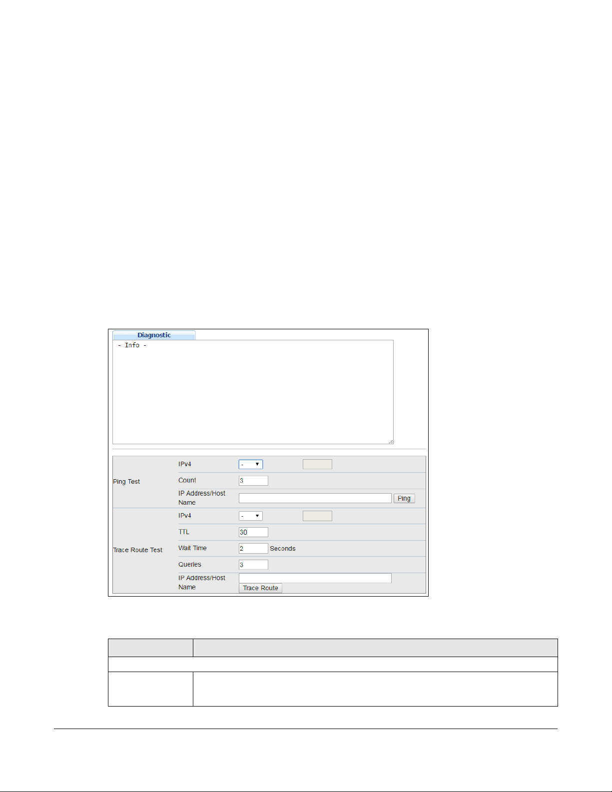
9.1 Overview
This chapter explains the Diagnostic screen. You can use this screen to help you identify problems.
9.2 Diagnostic
Click Management > Diagnostic in the navigation panel to open this screen. Use this screen to ping IP
addresses, run a traceroute, perform port tests or show the NSW’s location between devices.
Figure 47 Management > Diagnostic
CHAPTER 9
Diagnostic
The following table describes the labels in this screen.
Table 23 Management > Diagnostic
LABEL DESCRIPTION
Ping Test
IPv4
(NSW100 Series
only)
Select this option if you want to ping an IPv4 address, and select vlan to specify the ID
number of the VLAN to which the Switch is to send ping requests. Otherwise, select - to send
ping requests to all VLANs on the NSW.
NSW Series User’s Guide
58
Page 60

Chapter 9 Diagnostic
Table 23 Management > Diagnostic (continued)
LABEL DESCRIPTION
Count Enter the number of ICMP Echo Request (ping) messages the NSW continuously sends.
IP Address/Host
Name
Trace Route Test
IPv4
(NSW100 Series
only)
Type the IP address or host name of a device that you want to ping in order to test a
connection.
Click Ping to have the NSW ping the IP address.
Select this option if you want to trace the route packets take to a device with an IPv4
address, and select vlan to specify the ID number of the VLAN on which the NSW traces the
path. Otherwise, select - to trace the path on any VLAN.
The device to which you want to run a traceroute must belong to the VLAN you
specify here.
TTL Enter the Time To Live (TTL) value for the ICMP Echo Request packets. This is to set the
maximum number of the hops (routers) a packet can travel through. Each router along the
path will decrement the TTL value by one and forward the packets. When the TTL value
becomes zero and the destination is not found, the router drops the packets and informs the
sender.
Wait Time Specify how many seconds the NSW waits for a response to a probe before running another
Queries Specify how many times the NSW performs the traceroute function.
IP Address/Host
Name
traceroute.
Enter the IP address or host name of a device to which you want to perform a traceroute.
Click Trace Route to have the NSW perform the traceroute function. This determines the path
a packet takes to the specified device.
NSW Series User’s Guide
59
Page 61

CHAPTER 10
Troubleshooting
This chapter offers some suggestions to solve problems you might encounter. The potential problems are
divided into the following categories.
• Power, Hardware Connections, and LEDs
• NSW Access and Login
• NSW Configuration
10.1 Power, Hardware Connections, and LEDs
The NSW does not turn on. None of the LEDs turn on.
1 Make sure you are using the power adaptor or cord included with the NSW.
2 Make sure the power adaptor or cord is connected to the NSW and plugged in to an appropriate
power source. Make sure the power source is turned on.
3 Disconnect and re-connect the power adaptor or cord to the NSW.
4 If the problem continues, contact the vendor.
One of the LEDs does not behave as expected.
1 Make sure you understand the normal behavior of the LED. See Section 3.3 on page 21.
2 Check the hardware connections. See Section 10.1 on page 59.
3 Inspect your cables for damage. Contact the vendor to replace any damaged cables.
4 Disconnect and re-connect the power adaptor or cord to the NSW.
5 If the problem continues, contact the vendor.
NSW Series User’s Guide
59
Page 62

Chapter 10 Troubleshooting
10.2 NSW Access and Login
I forgot the IP address for the NSW.
1 The default IP address is http://DHCP-assigned IP.
2 Use the NCC, the ZON utility, or the console port to find the IP address.
3 If you’re using the console port, use the command line “show ip” to find the IP address.
I forgot the username and/or password.
1 The default username is admin and the default password is assigned by the NCC when the NSW is
registered with the NCC or 1234.
2 If this does not work, you have to reset the device to its factory defaults. See Section 4.6 on page 28.
I cannot see or access the Login screen in the web configurator.
1 Make sure you are using the correct IP address.
• The default IP address is http://DHCP-assigned IP.
• If you changed the IP address, use the new IP address.
• If you changed the IP address and have forgotten it, see the troubleshooting suggestions for I
forgot the IP address for the NSW.
2 Check the hardware connections, and make sure the LEDs are behaving as expected. See Section 3.3
on page 21.
3 Make sure your Internet browser does not block pop-up windows and has JavaScripts and Java
enabled.
4 Make sure your computer is in the same subnet as the NSW. (If you know that there are routers between
your computer and the NSW, skip this step.)
5 Reset the device to its factory defaults, and try to access the NSW with the default IP address. See
Section 4.6 on page 28.
6 If the problem continues, contact the vendor.
I can see the Login screen, but I cannot log in to the NSW.
NSW Series User’s Guide
60
Page 63

Chapter 10 Troubleshooting
1 Make sure you have entered the user name and password correctly. The default user name is admin,
and the default password is assigned by the NCC when the NSW is registered with the NCC or 1234.
These fields are case-sensitive, so make sure [Caps Lock] is not on.
2 Disconnect and re-connect the cord to the NSW.
3 If this does not work, you have to reset the device to its factory defaults. See Section 4.6 on page 28.
Pop-up Windows, JavaScripts and Java Permissions
In order to use the web configurator you need to allow:
• Web browser pop-up windows from your device.
• JavaScripts (enabled by default).
• Java permissions (enabled by default).
10.3 NSW Configuration
I cannot access the NCC portal.
• Check that you are using the correct URL:
• NCC: https://nebula.zyxel.com/
• Make sure your computer’s Ethernet card is installed and functioning properly.
• Check that you have Internet access. In your computer, click Start, (All) Programs, Accessories and
then Command Prompt. In the Command Prompt window, type ‘ping’ followed by a website such as
‘zyxel.com’. If you get a reply try to ping ‘nebula.zyxel.com’.
• Make sure you are using the correct web browser. Browsers supported are:
• Firefox 21 or later
• Chrome 26.0 or later
• IE 10 or later
• Internet Explorer 9.0 or later
• Safari 6.0 or later
I cannot log into the NCC portal.
• Open your web browser and go to https://portal.myzyxel.com. Sign in with the correct email and
password. Click Not a Member Yet if you don't have a myZyxel.com account and create an account.
• Then go to https://nebula.zyxel.com using a supported web browser.
NSW Series User’s Guide
61
Page 64

APPENDIX A
Customer Support
In the event of problems that cannot be solved by using this manual, you should contact your vendor. If
you cannot contact your vendor, then contact a Zyxel office for the region in which you bought the
device.
See http://www.zyxel.com/homepage.shtml and also
http://www.zyxel.com/about_zyxel/zyxel_worldwide.shtml for the latest information.
Please have the following information ready when you contact an office.
Required Information
• Product model and serial number.
• Warranty Information.
• Date that you received your device.
• Brief description of the problem and the steps you took to solve it.
Corporate Headquarters (Worldwide)
Taiwan
• Zyxel Communications Corporation
• http://www.zyxel.com
Asia
China
• Zyxel Communications (Shanghai) Corp.
Zyxel Communications (Beijing) Corp.
Zyxel Communications (Tianjin) Corp.
• http://www.zyxel.cn
India
•Zyxel Technology India Pvt Ltd
• http://www.zyxel.in
Kazakhstan
•Zyxel Kazakhstan
• http://www.zyxel.kz
NSW Series User’s Guide
62
Page 65

Korea
• Zyxel Korea Corp.
• http://www.zyxel.kr
Malaysia
• Zyxel Malaysia Sdn Bhd.
• http://www.zyxel.com.my
Pakistan
• Zyxel Pakistan (Pvt.) Ltd.
• http://www.zyxel.com.pk
Philippines
• Zyxel Philippines
• http://www.zyxel.com.ph
Singapore
• Zyxel Singapore Pte Ltd.
• http://www.zyxel.com.sg
Appendix A Customer Support
Europe
Taiwan
• Zyxel Communications Corporation
• http://www.zyxel.com/tw/zh/
Thailand
• Zyxel Thailand Co., Ltd
• http://www.zyxel.co.th
Vietnam
• Zyxel Communications Corporation-Vietnam Office
• http://www.zyxel.com/vn/vi
Austria
•Zyxel Deutschland GmbH
• http://www.zyxel.de
Belarus
•Zyxel BY
• http://www.zyxel.by
NSW Series User’s Guide
63
Page 66

Appendix A Customer Support
Belgium
• Zyxel Communications B.V.
• http://www.zyxel.com/be/nl/
• http://www.zyxel.com/be/fr/
Bulgaria
•Zyxel България
• http://www.zyxel.com/bg/bg/
Czech Republic
• Zyxel Communications Czech s.r.o
• http://www.zyxel.cz
Denmark
• Zyxel Communications A/S
• http://www.zyxel.dk
Estonia
• Zyxel Estonia
• http://www.zyxel.com/ee/et/
Finland
• Zyxel Communications
• http://www.zyxel.fi
France
•Zyxel France
• http://www.zyxel.fr
Germany
•Zyxel Deutschland GmbH
• http://www.zyxel.de
Hungary
• Zyxel Hungary & SEE
• http://www.zyxel.hu
Italy
• Zyxel Communications Italy
• http://www.zyxel.it/
NSW Series User’s Guide
64
Page 67

Appendix A Customer Support
Latvia
•Zyxel Latvia
• http://www.zyxel.com/lv/lv/homepage.shtml
Lithuania
•Zyxel Lithuania
• http://www.zyxel.com/lt/lt/homepage.shtml
Netherlands
• Zyxel Benelux
• http://www.zyxel.nl
Norway
• Zyxel Communications
• http://www.zyxel.no
Poland
• Zyxel Communications Poland
• http://www.zyxel.pl
Romania
• Zyxel Romania
• http://www.zyxel.com/ro/ro
Russia
• Zyxel Russia
• http://www.zyxel.ru
Slovakia
• Zyxel Communications Czech s.r.o. organizacna zlozka
• http://www.zyxel.sk
Spain
• Zyxel Communications ES Ltd
• http://www.zyxel.es
Sweden
• Zyxel Communications
• http://www.zyxel.se
Switzerland
•Studerus AG
NSW Series User’s Guide
65
Page 68

• http://www.zyxel.ch/
Turkey
• Zyxel Turkey A.S.
• http://www.zyxel.com.tr
UK
• Zyxel Communications UK Ltd.
• http://www.zyxel.co.uk
Ukraine
•Zyxel Ukraine
• http://www.ua.zyxel.com
Latin America
Argentina
• Zyxel Communication Corporation
• http://www.zyxel.com/ec/es/
Appendix A Customer Support
Brazil
• Zyxel Communications Brasil Ltda.
• https://www.zyxel.com/br/pt/
Ecuador
• Zyxel Communication Corporation
• http://www.zyxel.com/ec/es/
Middle East
Israel
• Zyxel Communication Corporation
• http://il.zyxel.com/homepage.shtml
Middle East
• Zyxel Communication Corporation
• http://www.zyxel.com/me/en/
NSW Series User’s Guide
66
Page 69

North America
USA
• Zyxel Communications, Inc. - North America Headquarters
• http://www.zyxel.com/us/en/
Oceania
Australia
• Zyxel Communications Corporation
• http://www.zyxel.com/au/en/
Africa
South Africa
• Nology (Pty) Ltd.
• http://www.zyxel.co.za
Appendix A Customer Support
NSW Series User’s Guide
67
Page 70

Copyright
Copyright © 2017 by Zyxel Communications Corporation.
The contents of this publication may not be reproduced in any part or as a whole, transcribed, stored in a retrieval system, translated into any
language, or transmitted in any form or by any means, electronic, mechanical, magnetic, optical, chemical, photocopying, manual, or
otherwise, without the prior written permission of Zyxel Communications Corporation.
Published by Zyxel Communications Corporation. All rights reserved.
Disclaimer
Zyxel does not assume any liability arising out of the application or use of any products, or software described herein. Neither does it convey any
license under its patent rights nor the patent rights of others. Zyxel further reserves the right to make changes in any products described herein
without notice. This publication is subject to change without notice.
Regulatory Notice and Statement
United States of America
APPENDIX B
Legal Information
The following information applies if you use the product within USA area.
Federal Communications Commission (FCC) EMC Statement
• This device complies with Part 15 of FCC rules. Operation is subject to the following two conditions:
• Changes or modifications not expressly approved by the party responsible for compliance could void the user’s authority to operate the
• This equipment has been tested and found to comply with the limits for a Class A digital device, pursuant to part 15 of the FCC Rules. These
Canada
The following information applies if you use the product within Canada area.
Industry Canada ICES statement
CAN ICES-3 (A)/NMB-3(A)
European Union
The following information applies if you use the product within the European Union.
CE EMC statement
WARNING: This equipment is compliant with Class A of EN55032. In a residential environment this equipment may cause radio interference.
(1) This device may not cause harmful interference.
(2) This device must accept any interference received, including interference that may cause undesired operations.
equipment.
limits are designed to provide reasonable protection against harmful interference when the equipment is operated in a commercial
environment. This equipment generates, uses, and can radiate radio frequency energy and, if not installed and used in accordance with the
instruction manual, may cause harmful interference to radio communications. Operation of this equipment in a residential area is likely to
cause harmful interference in which case the user will be required to correct the interference at his own expense.
NSW Series User’s Guide
68
Page 71

Appendix B Legal Information
List of National Codes
COUNTRY ISO 3166 2 LETTER CODE COUNTRY ISO 3166 2 LETTER CODE
Austria AT Liechtenstein LI
Belgium BE Lithuania LT
Bulgaria BG Luxembourg LU
Croatia HR Malta MT
Cyprus CY Netherlands NL
Czech Republic CZ Norway NO
Denmark DK Poland PL
Estonia EE Portugal PT
Finland FI Romania RO
France FR Serbia RS
Germany DE Slovakia SK
Greece GR Slovenia SI
Hungary HU Spain ES
Iceland IS Sweden SE
Ireland IE Switzerland CH
Italy IT Turkey TR
Latvia LV United Kingdom GB
Safety Warnings
• To avoid possible eye injury, do NOT look into an operating fiber-optic module’s connector.
• Do not use this product near water, for example, in a wet basement or near a swimming pool.
• Do not expose your device to dampness, dust or corrosive liquids.
• Do not store things on the device.
• Do not obstruct the device ventilation slots as insufficient airflow may harm your device. For example, do not place the device in an
enclosed space such as a box or on a very soft surface such as a bed or sofa.
• Do not install, use, or service this device during a thunderstorm. There is a remote risk of electric shock from lightning.
• Connect ONLY suitable accessories to the device.
• Do not open the device or unit. Opening or removing covers can expose you to dangerous high voltage points or other risks. Only qualified
service personnel should service or disassemble this device. Please contact your vendor for further information.
• Make sure to connect the cables to the correct ports.
• Place connecting cables carefully so that no one will step on them or stumble over them.
• Always disconnect all cables from this device before servicing or disassembling.
• Do not remove the plug and connect it to a power outlet by itself; always attach the plug to the power adaptor first before connecting it to
a power outlet.
• Do not allow anything to rest on the power adaptor or cord and do NOT place the product where anyone can walk on the power adaptor
or cord.
• Please use the provided or designated connection cables/power cables/ adaptors. Connect it to the right supply voltage (for example,
110V AC in North America or 230V AC in Europe). If the power adaptor or cord is damaged, it might cause electrocution. Remove it from the
device and the power source, repairing the power adapter or cord is prohibited. Contact your local vendor to order a new one.
• Do not use the device outside, and make sure all the connections are indoors. There is a remote risk of electric shock from lightning.
• Caution: Risk of explosion if battery is replaced by an incorrect type, dispose of used batteries according to the instruction. Dispose them at
the applicable collection point for the recycling of electrical and electronic device. For detailed information about recycling of this product,
please contact your local city office, your household waste disposal service or the store where you purchased the product.
• Use ONLY power wires of the appropriate wire gauge for your device. Connect it to a power supply of the correct voltage.
• Fuse Warning! Replace a fuse only with a fuse of the same type and rating.
• The POE (Power over Ethernet) devices that supply or receive power and their connected Ethernet cables must all be completely indoors.
• The following warning statements apply, where the disconnect device is not incorporated in the device or where the plug on the power
supply cord is intended to serve as the disconnect device,
- For permanently connected devices, a readily accessible disconnect device shall be incorporated external to the device;
- For pluggable devices, the socket-outlet shall be installed near the device and shall be easily accessible.
• This device must be grounded. Never defeat the ground conductor or operate the device in the absence of a suitably installed ground
conductor. Contact the appropriate electrical inspection authority or an electrician if you are uncertain that suitable grounding is available.
• When connecting or disconnecting power to hot-pluggable power supplies, if offered with your system, observe the following guidelines:
- Install the power supply before connecting the power cable to the power supply.
- Unplug the power cable before removing the power supply.
- If the system has multiple sources of power, disconnect power from the system by unplugging all power cables from the power supply.
• CLASS 1 LASER PRODUCT (for products with mini-GBIC slots or laser products, such as fiber-optic transceiver and GPON products).
• PRODUCT COMPLIES WITH 21 CFR 1040.10 AND 1040.11. (for products with mini-GBIC slots or laser products, such as fiber-optic transceiver and
GPON products)
•
• APPAREIL À LASER DE CLASS 1 (for products with mini-GBIC slots or laser products, such as fiber-optic transceiver and GPON products).
• PRODUIT CONFORME SELON 21 CFR 1040.10 ET 1040.11. (for products with mini-GBIC slots or laser products, such as fiber-optic transceiver and
GPON products)
NSW Series User’s Guide
69
Page 72

Environment Statement
European Union - Disposal and Recycling Information
The symbol below means that according to local regulations your product and/or its battery shall be disposed of separately from domestic
waste. If this product is end of life, take it to a recycling station designated by local authorities. At the time of disposal, the separate collection of
your product and/or its battery will help save natural resources and ensure that the environment is sustainable development.
Die folgende Symbol bedeutet, dass Ihr Produkt und/oder seine Batterie gemäß den örtlichen Bestimmungen getrennt vom Hausmüll entsorgt
werden muss. Wenden Sie sich an eine Recyclingstation, wenn dieses Produkt das Ende seiner Lebensdauer erreicht hat. Zum Zeitpunkt der
Entsorgung wird die getrennte Sammlung von Produkt und/oder seiner Bat terie dazu beitragen, natürliche Res sourcen zu sparen und die Umwelt
und die menschliche Gesundheit zu schützen.
El símbolo de abajo indica que según las regulaciones locales, su producto y/o su batería deberán depositarse como basura separada de la
doméstica. Cuando este producto alcance el final de su vida útil, llévelo a un punto limpio. Cuando llegue el momento de desechar el
producto, la recogida por separado éste y/o su batería ayudará a salvar los recursos naturales y a proteger la salud humana y
medioambiental.
Le symbole ci-dessous signifie que selon les réglementations locales votre produit et/ou sa batterie doivent être éliminés séparément des ordures
ménagères. Lorsque ce produit atteint sa fin de vie, amenez-le à un centre de recyclage. Au moment de la mise au rebut, la collecte séparée
de votre produit et/ou de sa batterie aidera à économiser les ressources naturelles et protéger l'environnement et la santé humaine.
Il simbolo sotto significa che secondo i regolamenti locali il vostro prodotto e/o batteria deve essere smaltito separatamente dai rifiuti domestici.
Quando questo prodotto raggiunge la fine della vita di servizio portarlo a una stazione di riciclaggio. Al momento dello smaltimento, la raccolta
separata del vostro prodotto e/o della sua batteria aiuta a risparmiare risorse naturali e a proteggere l'ambiente e la salute umana.
Symbolen innebär att enligt lokal lagstiftning ska produkten och/eller dess batteri kastas separat från hushållsavfallet. När den här produkten når
slutet av sin livslängd ska du ta den till en återvinningsstation. Vid tiden för kasseringen bidrar du till en bättre miljö och mänsklig hälsa genom att
göra dig av med den på ett återvinningsställe.
Appendix B Legal Information
NSW Series User’s Guide
70
Page 73

Environmental Product Declaration
Appendix B Legal Information
NSW Series User’s Guide
71
Page 74
台灣
Appendix B Legal Information
警告使用者:
• 這是甲類的資訊產品,在居住的環境中使用時,可能會造成射頻干擾,在這種情況下,使用者會被要求採取某些適當的對策。」
安全警告 - 為了您的安全,請先閱讀以下警告及指示 :
• 請勿將此產品接近水、火焰或放置在高溫的環境。
• 避免設備接觸
- 任何液體 - 切勿讓設備接觸水、雨水、高濕度、污水腐蝕性的液體或其他水份。
- 灰塵及污物 - 切勿接觸灰塵、污物、沙土、食物或其他不合適的材料。
• 雷雨天氣時,不要安裝,使用或維修此設備。有遭受電擊的風險。
• 切勿重摔或撞擊設備,並勿使用不正確的電源變壓器。
• 若接上不正確的電源變壓器會有爆炸的風險。。
• 請勿隨意更換產品內的電池。
• 如果更換不正確之電池型式,會有爆炸的風險,請依製造商說明書處理使用過之電池。
• 請將廢電池丟棄在適當的電器或電子設備回收處。
• 請勿將設備解體。
• 請勿阻礙設備的散熱孔,空氣對流不足將會造成設備損害。
• 請插在正確的電壓供給插座 ( 如 : 北美 / 台灣電壓 110V AC,歐洲是 230V AC)。
• 假若電源變壓器或電源變壓器的纜線損壞,請從插座拔除,若您還繼續插電使用,會有觸電死亡的風險。
• 請勿試圖修理電源變壓器或電源變壓器的纜線,若有毀損,請直接聯絡您購買的店家,購買一個新的電源變壓器。
• 請勿將此設備安裝於室外,此設備僅適合放置於室內。
• 請勿隨一般垃圾丟棄。
• 請參閱產品背貼上的設備額定功率。
• 請參考產品型錄或是彩盒上的作業溫度。
• 設備必須接地,接地導線不允許被破壞或沒有適當安裝接地導線,如果不確定接地方式是否符合要求可聯繫相應的電氣檢驗機構檢驗。
• 如果您提供的系統中有提供熱插拔電源,連接或斷開電源請遵循以下指導原則
- 先連接電源線至設備連,再連接電源。
- 先斷開電源再拔除連接至設備的電源線。
- 如果系統有多個電源,需拔除所有連接至電源的電源線再關閉設備電源。
• 產品沒有斷電裝置或者採用電源線的插頭視為斷電裝置的一部分,以下警語將適用 :
- 對永久連接之設備, 在設備外部須安裝可觸及之斷電裝置;
- 對插接式之設備, 插座必須接近安裝之地點而且是易於觸及的。
About the Symbols
Various symbols are used in this product to ensure correct usage, to prevent danger to the user and others, and to prevent property damage.
The meaning of these symbols are described below. It is important that you read these descriptions thoroughly and fully understand the
contents.
Explanation of the Symbols
SYMBOL EXPLANATION
Viewing Certifications
Go to http://www.zyxel.com to view this product’s documentation and certifications.
Zyxel Limited Warranty
Zyxel warrants to the original end user (purchaser) that this product is free from any defects in material or workmanship for a specific period (the
Warranty Period) from the date of purchase. The Warranty Period varies by region. Check with your vendor and/or the authorized Zyxel local
Alternating current (AC):
AC is an electric current in which the flow of electric charge periodically reverses direction.
Direct current (DC):
DC if the unidirectional flow or movement of electric charge carriers.
Earth; ground:
A wiring terminal intended for connection of a Protective Earthing Conductor.
Class II equipment:
The method of protection against electric shock in the case of class II equipment is either double insulation
or reinforced insulation.
NSW Series User’s Guide
72
Page 75

distributor for details about the Warranty Period of this product. During the warranty period, and upon proof of purchase, should the product
have indications of failure due to faulty workmanship and/or materials, Zyxel will, at its discretion, repair or replace the defective products or
components without charge for either parts or labor, and to whatever extent it shall deem necessary to restore the product or components to
proper operating condition. Any replacement will consist of a new or re-manufactured functionally equivalent product of equal or higher value,
and will be solely at the discretion of Zyxel. This warranty shall not apply if the product has been modified, misused, tampered with, damaged by
an act of God, or subjected to abnormal working conditions.
Note
Repair or replacement, as provided under this warranty, is the exclusive remedy of the purchaser. This warranty is in lieu of all other warranties,
express or implied, including any implied warranty of merchantability or fitness for a particular use or purpose. Zyxel shall in no event be held
liable for indirect or consequential damages of any kind to the purchaser.
To obtain the services of this warranty, contact your vendor. You may also refer to the warranty policy for the region in which you bought the
device at http://www.zyxel.com/web/support_warranty_info.php.
Registration
Register your product online to receive e-mail notices of firmware upgrades and information at www.zyxel.com for global products, or at
www.us.zyxel.com for North American products.
Trademarks
ZyNOS (Zyxel Network Operating System) and ZON (Zyxel One Network)are registered trademarks of Zyxel Communications, Inc. Other
trademarks mentioned in this publication are used for identification purposes only and may be properties of their respective owners.
Open Source Licenses
This product contains in part some free software distributed under GPL license terms and/or GPL like licenses. Open source licenses are provided
with the firmware package. You can download the latest firmware at www.zyxel.com. To obtain the source code covered under those Licenses,
please contact support@zyxel.com.tw to get it.
Appendix B Legal Information
NSW Series User’s Guide
73
Page 76

Index
Index
Numbers
802.1P priority 40
A
applications
backbone 9
bridging 10
IEEE 802.1Q VLAN 11
auto-crossover 18
B
back up, configuration file 53
basic settings 32
D
default Ethernet settings 18
default IP 8, 36
diagnostics 57
ping 58
disclaimer 68
DNS 41
DNS (Domain Name System) 41
Domain Name System 41
dual firmware images 51
E
Ethernet MAC 33
F
C
certifications
viewing 72
CNC
portal 61
configuration
change running config 51
saving 27
configuration file
backup 53
restore 53
saving 50
console port 20
contact information 62
copyright 68
customer support 62
FCC interference statement 68
file transfer using FTP
command example 55
filename convention, configuration
configuration
file names 55
firmware 33
upgrade 52
front panel 17
FTP 55
file transfer procedure 56
G
getting help 29
Gigabit ports 17
NSW Series User’s Guide
74
Page 77

Index
H
hardware installation 13
hardware monitor 33
hardware overview 17
I
installation
desktop 13
precautions 14
rack-mounting 14
transceivers 19
installation scenarios 13
IP address 37
IP setup 34
IP subnet mask 37
L
LEDs 21
lockout 28
login 25
using the command interface. See command
interface. 11
MDIX (Media Dependent Interface Crossover) 18
Media Access Control 33
mounting brackets 14
N
network applications 9
P
ping, test connection 58
port setup 39
port VLAN ID, see PVID 47
ports
speed/duplex 40
power
voltage 34
power connector 21
power status 34
product registration 73
M
MAC 33
MAC (Media Access Control) 33
MAC address 33
maintanence
configuration backup 53
firmware 52
restoring configuration 53
maintenance 49
current configuration 50
main screen 50
management IP address 36, 37
managing the device
good habits 12
using FTP. See FTP. 11
using Telnet. See command interface. 11
R
rack-mounting 14
rear panel connections 21
reboot
load configuration 51
reboot system 51
registration
product 73
resetting 28, 50
to factory default settings 50
restoring configuration 28, 53
rubber feet 13
running configuration 50
erase 50
reset 50
NSW Series User’s Guide
75
Page 78

Index
S
save configuration 27, 50
Small Form-factor Pluggable (SFP) 19
static VLAN 44
control 46
tagging 46
status 26, 30
power 34
VLAN 42
switch lockout 28
switch reset 28
system information 32
system reboot 51
T
Tech-Support 54
log enhancement 54
temperature indicator 34
terminal emulation 20
trademarks 73
transceiver MultiSource Agreement (MSA) 19
transceivers 19
installation 19
removal 20
status 42, 43
trunking 48
VLAN number 35, 36, 37, 38
VLAN trunking 48
VT100 20
W
warranty 72
note 73
web configurator
getting help 29
home 26
login 25
logout 28
Z
ZyNOS (ZyXEL Network Operating System) 55
U
user name 25
default 25
V
ventilation holes 13
VID 35, 38, 43
VLAN
number of VLANs 43
port number 43
port settings 46
PVID 47
static VLAN 44
NSW Series User’s Guide
76
 Loading...