


R40W46 Series
Zenith R40W46 Series, R40W46F Series, R45W46 Series, R45W46F Series, R40W46FA Service Manual
...
SERVICE MANUAL
Product Type: Projection TV
Chassis: MP-03AA
Manual Series:
Manual Part #:
Model Line:
Product Year: 2003
R40W46
R40W46F
R45W46
R45W46F
Model Series:
CONTENTS
Product Specifications..................................................4
Description of Controls .................................................5
Adjustment Instructions...............................................14
Diagrams ...................................................................22
Parts List ...................................................................34
Schematics....................................................................
Published Oct. 2003
by Technical Publications
Zenith Electronics Corporation
201 James Record Road
Huntsville, Alabama 35824-1513
Copyright © 2003 by Zenith Electronics Corporation
Printed in Korea

- 2 -
PRODUCT SAFETY
IMPORTANT SAFETY NOTICE
This manual was prepared for use only by properly trained audiovisual service
technicians. When servicing this product, under no circumstances should the
original design be modified or altered without permission from Zenith
Electronics Corporation. All components should be replaced only with types
identical to those in the original circuit and their physical location, wiring, and
lead dress must conform to original layout upon completion of repairs. If any
fuse (or Fusible Resistor) in this TV receiver is blown, replace it only with the
factory specified fuse type and rating. When replacing a high wattage resistor
(Oxide Metal Film Resistor, over 1W), keep the resistor 10mm away from PCB.
Always keep wires away from high voltage or high temperature parts.
Special components are also used to prevent shock and fire hazard.
These components are indicated by the letter “x” included in their component
designators and are required to maintain safe performance. No deviations are
allowed without prior approval by Zenith Electronics Corporation. Service work
should be performed only after you are thoroughly familiar with these safety
checks and servicing guidelines.
Circuit diagrams may occasionally differ from the actual circuit used.
This way, implementation of the latest safety and performance improvement
changes into the set is not delayed until the new service literature is printed.
CAUTION: Do not attempt to modify this product in any way.
Never perform customized installations without manufacturer’s
approval.
Unauthorized modifications will not only void the warranty, but may
lead to property damage or user injury.
GENERAL GUIDANCE
An lsolation Transformer should always be used during the servicing
of a receiver whose chassis is not isolated from the AC power line. Use a
transformer of adequate power rating to protect against personal injury from
electrical shocks. It will also protect the receiver and its components from being
damaged by accidental shorts of the circuitry that may be inadvertently
introduced during the service operation.
Before returning the receiver to the customer, always perform an AC leakage
current check on the exposed metallic parts of the cabinet, such as antennas,
terminals, etc., to be sure the set is safe to operate
without damage of electrical shock.
LEAKAGE CURRENT COLD CHECK
(ANTENNA COLD CHECK)
With the instrument’s AC plug removed from AC source, connect an electrical
jumper across the two AC plug prongs. Place the AC switch in the on position,
connect one lead of ohm-meter to the AC plug prongs tied together, and touch
other ohm-meter lead in turn to each exposed metallic parts such as antenna
terminals, phone jacks, etc. If the exposed metallic part has a return path to the
chassis, the measured resistance should be between 1MΩ and 5.2MΩ. When
the exposed metal has no return path to the chassis the reading must be
infinite. Any other abnormality that exists must be corrected before
the receiver is returned to the customer.
ELECTROSTATICALLY SENSITIVE DEVICES
Some semiconductor (solid-state) devices can be damaged easily by static
electricity. Such components commonly are called Electrostatically Sensitive
(ES) Devices. Examples of typical ES devices are integrated circuits and some
field-effect transistors and semiconductor “chip” components. The following
techniques should be used to help reduce the incidence of component damage
caused by static electricity.
1. Immediately before handling any semiconductor component or
semiconductor-equipped assembly, drain off any electrostatic charge on the
body by touching a known earth ground. Alternatively, obtain and wear a
commercially available discharging wrist strap device, which should be
removed for potential shock reasons prior to applying power to the unit under
test.
2. After removing an electrical assembly equipped with ES devices, place the
assembly on a conductive surface such as an ESD mat, to prevent
electrostatic charge buildup or exposure of the assembly.
3. Use only a grounded-tip soldering iron to solder or unsolder ES devices.
4. Use only an anti-static solder removal device. Some solder removal devices
not classified as “anti-static” can generate electrical charges sufficient to
damage ES devices.
5. Do not use freon-propelled chemicals. These can generate electrical charge
sufficient to damage ES devices.
6. Do not remove a replacement ES device from its protective package until
immediately before you are ready to install it. (Most replacement ES devices
are packaged with leads electrically shorted together by conductive foam,
aluminum foil, or comparable conductive material.)
7. Immediately before removing the protective material from the leads of a
replacement ES device, touch the protective material to the chassis or circuit
assembly into which the device will be installed.
Caution: Be sure no power is applied to the chassis or circuit, and observe
all other safety precautions.
8. Minimize bodily motions when handling unpackaged replacement ES
devices. (Otherwise, seemingly harmless motion, such as the brushing
together of your clothing or the lifting of your foot from a carpeted floor, can
generate static electricity sufficient to damage an ES device.)
REGULATORY INFORMATION
This equipment has been tested and found to comply with the limits for a Class
B digital device, pursuant to Part 15 of the FCC Rules.
These limits are designed to provide reasonable protection against harmful
interference when the equipment is operated in a residential installation. This
equipment generates, uses and can radiate radio frequency energy and, if not
installed and used in accordance with the instruction manual, may cause
harmful interference to radio communications. However, there is no guarantee
that interference will not occur in a particular installation. If this equipment does
cause harmful interference to radio or television reception, which can be
determined by turning the equipment off and on, the user is encouraged to try
to correct the interference by one or more of the following measures: Reorient
or relocate the receiving antenna; Increase the separation between the
equipment and receiver; Connect the equipment into an outlet on a circuit
different from that to which the receiver is connected; Consult the dealer or an
experienced radio/TV technician for help.
The responsible party for this device’s compliance is:
Zenith Electronics Corporation
201 James Record Road
Huntsville, AL 35824, USA
Digital TV Hotline: 1-800-243-0000

- 3 -
SPECIFICATIONS.................................................................4
DESCRIPTION OF CONTROLS...........................................5
PROGRAMMING CODES.....................................................9
ADJUSTMENT INSTRUCTION...........................................14
PRINTED CIRCUIT BOARDS.............................................22
BLOCK DIAGRAM...............................................................32
EXPLODED VIEW..........................................................34,36
EXPLODED VIEW PARTS LIST....................................35,37
REPLACEMENT PARTS LIST............................................38
SCHEMATIC DIAGRAM..........................................................
PRINTED CIRCUIT BOARDS.................................................
TABLE OF CONTENTS

- 4 -
SPECIFICATIONS
Model R40W46, R40W46F, R45W46, R45W46F
Power requirements AC 120V
Television system NTSC
Television channels VHF : 2 ~ 13, UHF : 14 ~ 69
Cable : 01 ~ 125
Power consumption See the back of the TV
External antenna impedance 75 Ω
Audio output 15W + 15W
External input ports Video input jacks (4 sets)
S-video input port (2)
Component input jacks (2 sets)
DVI-HDTV input jack (1)
Variable audio output jacks (1 set)
Monitor output jack (1)
- 5 -
DESCRIPTION OF CONTROLS
1 2 3
4 5 6
7 8 9
0
tv
vcr
cable
dvd
sat
mode
light
power
tv/video
sleep
comp/dvi
flashbk
ccarc
video
audio
fcr
mute
vol
ch
swappipch- pipch+
pip
still
pip input position
mts
menu exit
recordstop
pause
rew
play
ff
skip
right
enter
left
down
up
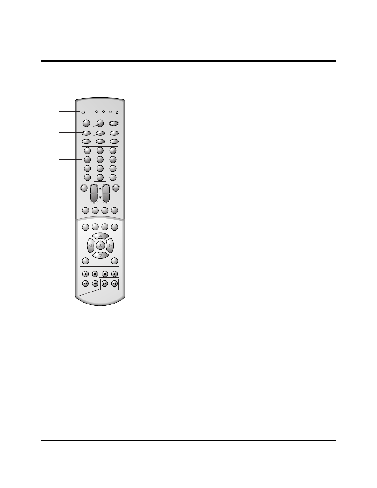
1. MODE INDICATOR LIGHTS
Show active remote mode every time any button is
pressed.
2. MODE
Selects the remote operating mode: TV, VCR, Cable,
DVD and Satellite. Select other operating modes, for the
remote to control external devices.
3. LIGHT
Illuminates the remote control keys.
4. TV/VIDEO
Selects TV, VIDEO, COMPONENT, or DVI mode.
5. COMP/DVI
Selects COMPONENT or DVI mode.
6. ARC
Selects 4:3, 16:9, Horizon, Zoom 1, or Zoom 2 picture formats.
7. NUMBER BUTTONS
Direct channel selection.
8. VIDEO
Selects factory preset picture settings:
Clear, Optimum, Soft,
or
User.
9. FCR ( Favorite Channel Review )
Selects favorite channels.
Refer to "Favorite channel memory".
10.CHANNEL UP/DOWN
• Selects the desired channel.
• Selects the desired menu option when menu is
displayed on the screen.
VOLUME UP/DOWN
• Increase or decrease sound level.
• Enters or adjusts the selected menu when menu is
displayed on the screen.
11.STILL
Freezes still the sub picture in PIP mode.
Freezes the currently-viewed picture.
12.MENU
Displays on-screen menus.
13.VCR BUTTONS
Control some video cassette recorders.
14.SKIP Left/Right
Playing CDs: Selects previous/next song.
Playing DVDs: Selects previous/next movie chapter.
1
2
3
4
6
7
8
9
11
10
12
13
14
5
- 6 -
DESCRIPTION OF CONTROLS
1 2 3
4 5 6
7 8 9
0
tv
vcr
cable
dvd
sat
mode
light
power
tv/video
sleep
comp/dvi
flashbk
ccarc
video
audio
fcr
mute
vol
ch
swappipch- pipch+
pip
still
pip input position
mts
menu exit
recordstop
pause
rew
play
ff
skip
right
enter
left
down
up
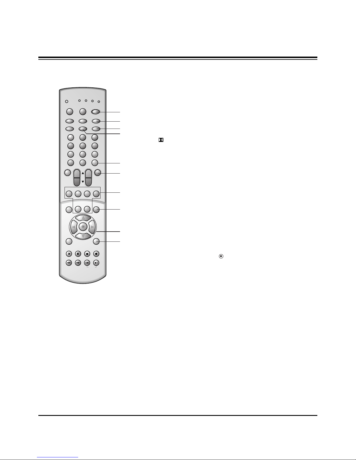
15.POWER (or ON/OFF)
Refer to "Turning the TV on/off".
16.SLEEP
Sets desired sleep time.
17.FLASHBK
Returns to the previous channel.
18. CC
Selects the CAPTIONS:
On, EZ Mute, or Off.
19.AUDIO
Selects the sound appropriate for the program's
character;
Virtual, Flat, Music, Movie, Sports or User.
20.MUTE
Reduce to half level of original sound or mute the sound.
21.PIP (Picture-in-Picture)
PIP
Selects the PIP mode, twin picture window, or POP
mode.
PIPCH +
/
-
Selects the sub picture channel.
SWAP
Switches the main and sub pictures.
PIP INPUT
Selects the input signal for the sub picture.
POSITION
Moves the sub picture to another corner of the main
picture.
22. MTS BUTTON
Selects MTS sound:
Mono, Stereo, or SAP.
23.UP
D
/ DOWNE/ LEFTF/ RIGHTG/ ENTER
• Navigates the on-screen menus and adjusts the system
settings and preferences.
• Recalls current TV mode (Remote control only).
24.EXIT
Clears all on-screen displays and returns to TV viewing
from any menu.
15
17
23
24
18
16
19
20
21
22

- 7 -
DESCRIPTION OF CONTROLS
Fixation of TV movement:
• To prevent the movement of the projection TV, fix
TV’s caster with 4 stopper as shown.
• Casters (on the bottom)
Turn and move the TV easily.
Stopper
ch
volmuteentermenutv/video
on/off
26
15 4 12 23 20 25 10
This is a simplified representation of front panel.
25.STAND BY INDICATOR (O)
Illuminates brightly when the TV is in standby mode. Dims when the TV is switched on.
26.REMOTE CONTROL SENSOR

- 8 -
DESCRIPTION OF CONTROLS
1. IN 1 JACKS : Connect external equipment outputs (VCR, DVD, CAMCORDER) to these
inputs. Press the tv/video button to select
Video 1.
2. IN 2 JACKS : Connect external equipment outputs (VCR, DVD, CAMCORDER) to these inputs. Press
the tv/video button to select
Video 2.
3. IN 3 JACKS : Connect external equipment outputs (VCR, DVD, CAMCORDER) to these inputs. Press
the tv/video button to select
Video 3.
4. IN 4 JACKS : Connect external equipment outputs (VCR, DVD, CAMCORDER) to these inputs. Press
the tv/video button to select
Video 4.
5. MONITOR OUTPUT JACKS : Connect second TV or a monitor to these outputs for monitoring the
selected program.
6. VARIABLE AUDIO OUT JACKS: Connect analog stereo amplifier to your front speaker.
7. DVD/DTV INPUT JACKS : Connect component output jacks to these inputs. Use the tv/video or
comp/dvi button to select
Component 1, Component 2.
8. DVI-HDTV INPUT JACK: Connect set-top box to these input. Use the tv/video or comp/dvi button to
select
DVI.
Note : Avoid having a fixed image remain in the screen for a long period of time. Typically a frozen still
picture from a VCR is present ; the fixed image may remain visible on the screen.
Easy A/V Connection
If a external equipment is disconnected, the TV
displays as shown right and you can only select input
source connected with tv/video or comp/dvi button
on the remote control. (It’s not available in DVI input
source.)
ANT IN
75Ω
L
L
(R)
(L)
(R)
(L)
Y
PB
PR
Y
PB
PR
COMPONENT 1
DVD/DTV INPUT
(480i/480p/1080i)
COMPONENT 2
S - VIDEO
( )
VIDEO
VIDEO
(L)-AUDIO-(R)
MONITOR
OUTPUT
IN 2
DVI
AUDIO
(L)-AUDIO-(R)
VARIABLE
AUDIO OUTPUT
IN 4
IN 1
AUDIO
VIDEO
MONO
MONO
DVI-HDTV INPUT
External Equipment Connection and Viewing Setup
S-VIDEO VIDEO
- AUDIO -
L/MONO
R
IN 3
1
7
3
2
4
6
8
5
S-VIDEO INPUT JACK
S-VIDEO
INPUT
JACK
You can connect additional equipment, such as VCRs, camcorders etc. to your TV.
Connection panels shown here may be somewhat different from your TV.
Here is an example drawing of a typical jackpack layout.
- 9 -
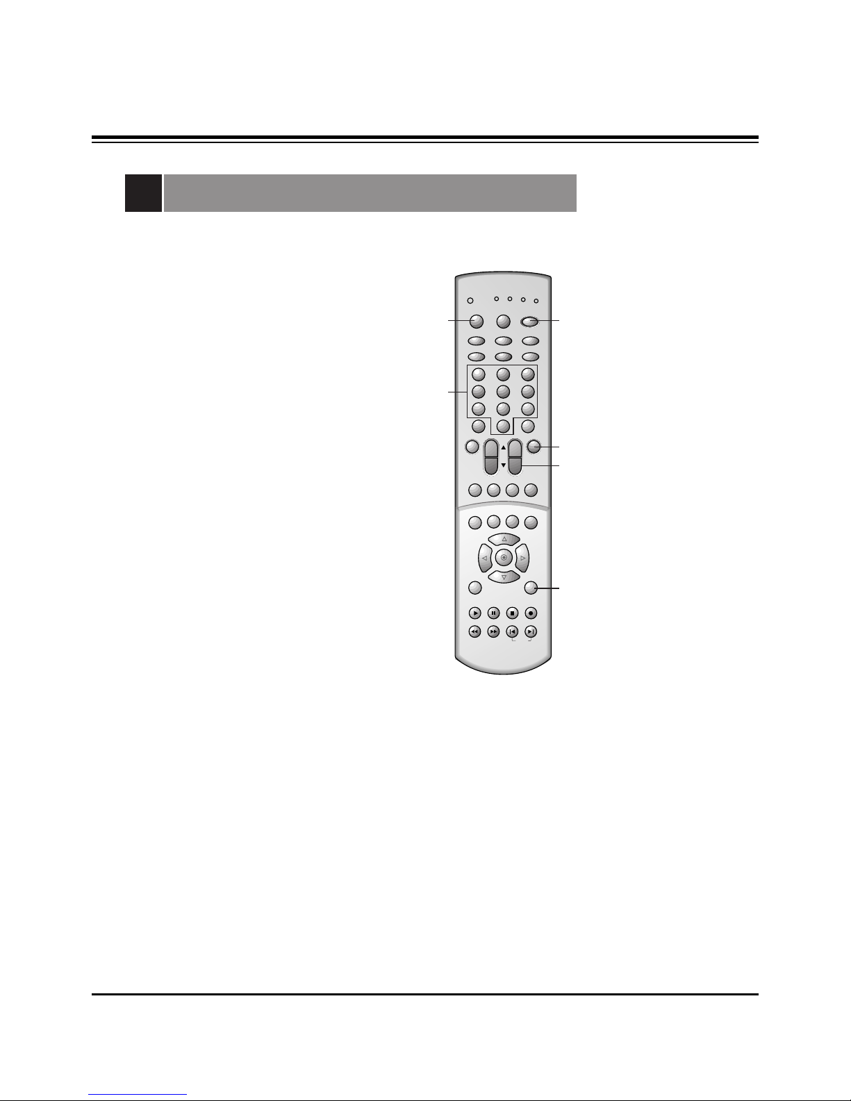
PROGRAMMING CODES
Programming the Remote
The remote control for your HD receiver is a multi-brand or universal
remote control. It can be programmed to operate most remotecontrollable devices of other manufacturers.
Note that the remote control may not control all models of other
brands.
1. Test your remote control.
To find out whether your remote control can operate the
component without programming, turn on the component such as
a VCR and press the corresponding mode button (VCR) on the
remote control, while pointing at the component. Test the POWER
and CH +/- buttons to see if the component responds properly. If
not, the remote requires programming to operate the device.
2. Turn on the component to be programmed, then press the
corresponding mode button on the remote control.
3. Press the POWER and MUTE buttons simultaneously, the remote
control is ready to be programmed for the code.
4. There are two ways to find the right code for the component.
A. If you press the CH +/- buttons repeatedly, the codes will
change one at-a-time. Press the POWER button after each code
change. If the right code is found, the device will turn off.
B. Enter a code number using the number buttons on the remote.
Programming code numbers for the corresponding component
can be found on the following pages. Again, if the code is correct,
the device will turn off.
5. Press the EXIT button to store the code.
6. Test the remote control functions to see if the component
responds properly. If not, repeat from step 2.
1 2 3
4 5 6
7 8 9
0
tv
vcr
cable
dvd
sat
mode
light
power
tv/video
sleep
comp/dvi
flashbk
ccarc
video
audio
fcr
mute
vol
ch
swappipch- pipch+
pip
still
pip input position
mts
menu exit
recordstop
pause
rew
play
ff
skip
right
enter
left
down
up
3/4
3
4
5
2
4

- 10 -
PROGRAMMING CODES
Programming Codes
TV
A MARK 112 143
ADMIRAL 072 081 161
AKAI 006 146
AMPRO 073 167
AMSTRAD 052
ANAM 043 054 056
080 104 108
112 115 118
121 131
AOC 004 006 058
112
BLAUPUNKT 088
CANDLE 002 003 004
006
CAPEHART 058
CETRONIC 043
CITIZEN 002 003 004
006 043 101
103 143
CLASSIC 043
CONCERTO 004
CONTEC 039 043 050
051
CORONADO 143
CRAIG 043 054
CROWN 043 143
CURTIS MATHES 004 006 101
116 143
CXC 043
DAEWOO 004 016 017
043 044 055
071 076 103
107 111 114
117 120 123
125 127 128
136 143
DAYTRON 004 116 143
DYNASTY 043
DYNATECH 062
ELECTROHOME 024 077 143
EMERSON 004 005 006
028 043 047
048 050 051
096 116 143
151 153 154
155
FISHER 007 057
FUNAI 028 043
FUTURETECH 043
GE 004 006 008
009 034 056
073 074 091
116 130 144
155 160 161
165
GOLDSTAR 004 102 106
110 112 113
116 119 122
127 137 143
HALL MARK 004 116
HITACHI 004 006 009
010 011 012
023 041 075
143 158 163
166
INFINITY 164
INKEL 129
JBL 164
JCPENNY 004 006 008
009 024 030
065 101 143
156 160
JENSEN 013
JVC 034 038 070
083 145
KEC 043
KENWOOD 006 070
KLOSS 002 059
KMC 143
KTV 006 043 143
154
LG 255
LODGENET 072
LOGIK 072
LUXMAN 004
LXI 007 015 052
081 160 164
166
MAGNAVOX 003 004 006
022 059 060
061 063 064
127 143 160
164
MARANTZ 006 077 164
MATSUI 164
MEMOREX 004 007 072
116
METZ 088
MGA 004 006 024
028 042 049
077 116
MINERVA 088
MITSUBISHI 004 006 024
028 040 042
109 116 124
146
MTC 004 006 062
101
NAD 015 025
NEC 006 007 016
019 024 040
056 130 132
134
NIKEI 043
ONKING 043
ONWA 043
OPTONICA 019 081
PANASONIC 034 056 080
092 164
PHILCO 003 004 006
024 043 056
059 060 063
064 127 143
164
PHILIPS 003 004 005
006 038 059
070 093 143
160 164
PIONEER 006 018 023
025 027 116
135 176
PORTLAND 004 143
PROSCAN 144 160 161
165 167
PROTON 004 058 116
131 143 171
173
QUASAR 034 056 092
RADIO SHACK 019 043 047
116 127 143
RCA 004 006 023
024 056 065
074 144 152
156 160 161
165
REALISTIC 007 019 043
047
ROCTEC 186
RUNCO 168 169
SAMPO 004 006 058
116
SAMSUNG 004 050 089
101 105 113
116 127 133
137 143 160
SANYO 007 020 021
033 039 053
057 082 166
SCOTT 004 028 043
048 116 143
SEARS 004 007 015
028 030 057
082 094 101
116 143 160
Sharp 004 014 019
022 028 029
081 143 170
175
SIEMENS 088
SIGNATURE 072
SONY 041 070 079
085 126 139
147 185
SOUNDESIGN 003 004 028
043 116
SPECTRICON 112
SSS 004 043
SUPRE MACY 002
SYLVANIA 003 004 006
044 059 060
063 064 116
127 140 160
164
TANDY 081
TATUNG 056 062
TECHNICS 034 080 084
TECHWOOD 004
TEKNIKA 002 003 004
006 024 028
031 043 072
077 101 103
143
TELEFUNKEN 037 046 086
087
TELERENT 072
TERA 172
TMK 004 116
TOSHIBA 007 015 030
040 051 062
101 138
TOTEVISION 143
UNIVERSAL 008 009
VIDEO CONCEPTS 146
VIDIKRON 174
VIDTECH 004 116
WARDS 004 008 009
019 028 060
061 063 064
072 074 116
143 164
YAMAHA 004 006
YORK 004 116
YUPITERU 043
ZENITH 001 072 073
095 103 157
ZONDA 112
Brand Codes Brand Codes Brand Codes Brand Codes

- 11 -
PROGRAMMING CODES
VCRs
AIWA 034
AKAI 016 043 046
124 125 146
AMPRO 072
ANAM 031 033 103
AUDIO DYNAMICS 012 023 039
043
BROKSONIC 035 037 129
CANON 028 031 033
CAPEHART 108
CRAIG 003 040 135
CURTIS MATHES 031 033 041
DAEWOO 005 007 010
064 065 108
110 111 112
116 117 119
DAYTRON 108
DBX 012 023 039
043
DYNATECH 034 053
ELECTROHOME 059
EMERSON 006 017 025
027 029 031
034 035 036
037 046 101
129 131 138
153
FISHER 003 008 009
010
FUNAI 034
GE 031 033 063
072 107 109
144 147
GO VIDEO 132 136
GOLDSTAR 012 013 020
101 106 114
123
HARMAN KARDON 012 045
HITACHI 004 018 026
034 043 063
137 150
INSTANTREPLAY 031 033
JCL 031 033
JCPENNY 012 013 015
033 040 066
101
JENSEN 043
JVC 012 031 033
043 048 050
055 060 130
150 152
KENWOOD 014 034 039
043 047 048
LG 255
LLOYD 034
LXI 003 009 013
014 017 034
101 106
MAGIN 040
MAGNAVOX 031 033 034
041 067 068
MARANTZ 012 031 033
067 069
MARTA 101
MATSUI 027 030
MEI 031 033
MEMOREX 003 010 014
031 033 034
053 072 101
102 134 139
MGA 045 046 059
MINOLTA 013 020
MITSUBISHI 013 020 045
046 049 051
059 061 151
MTC 034 040
MULTITECH 024 034
NEC 012 023 039
043 048
NORDMENDE 043
OPTONICA 053 054
PANASONIC 066 070 074
083 133 140
145
PENTAX 013 020 031
033 063
PHILCO 031 034 067
PHILIPS 031 033 034
054 067 071
101
PILOT 101
PIONEER 013 021 048
PORTLAND 108
PULSAR 072
QUARTZ 011 014
QUASAR 033 066 075
145
RCA 013 020 033
034 040 041
062 063 107
109 140 144
145 147
REALISTIC 003 008 010
014 031 033
034 040 053
054 101
RICO 058
RUNCO 148
SALORA 014
SAMSUNG 032 040 102
104 105 107
109 112 113
115 120 122
125
SANSUI 022 043 048
135
SANYO 003 007 010
014 102 134
SCOTT 017 037 112
129 131
SEARS 003 008 009
010 013 014
017 020 031
042 073 081
101
SHARP 031 054 149
SHINTOM 024
SONY 003 009 031
052 056 057
058 076 077
078 149
SOUNDESIGN 034
STS 013
SYLVANIA 031 033 034
059 067
SYMPHONIC 034
TANDY 010 034
TATUNG 039 043
TEAC 034 039 043
TECHNICS 031 033 070
TEKNIKA 019 031 033
034 101
THOMAS 034
TMK 006
TOSHIBA 008 013 042
047 059 082
112 131
TOTEVISION 040 101
UNITECH 040
VECTOR RESEARCH 012
VICTOR 048
VIDEO CONCEPTS 012 034 046
VIDEOSONIC 040
WARDS 003 013 017
024 031 033
034 040 053
054 131
YAMAHA 012 034 039
043
ZENITH 001 034 048
056 058 072
080 101
Brand Codes Brand Codes Brand Codes

- 12 -
PROGRAMMING CODES
Programming Codes
SAT
ALPHASTAR DSR 123
AMPLICA 050
BIRDVIEW 051 126 129
BSR 053
CAPETRONICS 053
CHANNEL MASTER 013 014 015
018 036 055
CHAPARRAL 008 009 012
077
CITOH 054
CURTIS MATHES 050 145
DRAKE 005 006 007
010 011 052
112 116 141
DX ANTENNA 024 046 056
076
ECHOSTAR 038 040 057
058 093 094
095 096 097
098 099 100
122
ELECTRO HOME 089
EUROPLUS 114
FUJITSU 017 021 022
027 133 134
GENERAL INSTRUMENT 003 004 016
029 031 059
101
HITACHI 139 140
HOUSTON TRACKER 033 037 039
051 057 104
HUGHES 068
HYTEK 053
JANIEL 060 147
JERROLD 061
KATHREIN 108
LEGEND 057
LG 255
LUTRON 132
LUXOR 062 144
MACOM 010 059 063
064 065
MEMOREX 057
NEXTWAVE 028 124 125
NORSAT 069 070
PACE SKY SATELLITE143
PANASONIC 060 142
PANSAT 121
PERSONAL CABLE 117
PHILIPS 071
PICO 105
PRESIDENT 019 102
PRIMESTAR 030 110 111
PROSAT 072
RCA 066 106
REALISTIC 043 074
SAMSUNG 123
SATELLITE SERVICE CO 028 035 047
057 085
SCIENTIFIC ATLANTA 032 138
SONY 103
STARCAST 041
SUPER GUIDE 020 124 125
TEECOM 023 026 075
087 088 090
107 130 137
TOSHIBA 002 127
UNIDEN 016 025 042
043 044 045
048 049 078
079 080 086
101 135 136
VIEWSTAR 115
WINEGARD 128 146
ZENITH 001 081 082
083 084 091
120
Brand Codes Brand Codes Brand Codes
DVD
APEX DIGITAL 022
DENON 020 014
GE 005 006
GOLDSTAR 010 016 025
HARMAN KARDON 027
JVC 012
LG 001 010 016
025
MAGNAVOX 013
MARANTZ 024
MITSUBISHI 002
NAD 023
ONKYO 008 017
PANASONIC 003 009
PHILIPS 013
PIONEER 004 026
PROCEED 021
PROSCAN 005 006
RCA 005 006
SAMSUNG 011 015
SONY 007
THOMPSON 005 006
TOSHIBA 019 008
YAMAHA 009 018
ZENITH 010 016 025
Brand Codes Brand Codes Brand Codes

- 13 -
PROGRAMMING CODES
CATV
ABC 003 004 039
042 046 052
053
ANTRONIK 014
ARCHER 005 007 014
024
CABLE STAR 026
CENTURION 092
CENTURY 007
CITIZEN 007
COLOUR VOICE 065 090
COMBANO 080 081
COMTRONICS 019 030
DIAMOND 023
EAGLE 020 030 040
EASTERN 057 062 066
ELECTRICORD 032
GE 072
GEMINI 008 022 025
054
GI 052 074
GOLDEN CHANNEL 030
HAMLIN 049 050 055
HITACHI 052 055
HOSPITALITY 070 077
JERROLD 002 003 004
008 009 010
052 069 074
LG 255
M-NET 037
MACOM 033
MAGNAVOX 010 012 064
079
MEMOREX 001
MOVIE TIME 028 032
NSC 015 028 038
071 073
OAK 016 031 037
053
PANASONIC 044 047
PARAGON 001
PHILIPS 006 012 013
020 065 085
090
PIONEER 034 051 052
063 076
POST NEWS WEEK 016
PRUCER 059
PTS 011 048 071
072 073 074
PULSAR 001
RCA 047
REGAL 049 050
REGENCY 057
REMBRANT 025
RK 091
SAMSUNG 030 068
SCIENTIFIC ATLANTA 003 011 041
042 043 045
046
SHERITECH 022
SIGNAL 030
SIGNATURE 052
SL MARX 030
SPRUCER 047 078
STARCOM 002 004 008
009
STARGATE 008 030
SYLVANIA 067
TADIRAN 030
TANDY 017
TEXSCAN 029 067
TOCOM 039 040 056
TOSHIBA 001
UNIKA 007 014 024
UNITED CABLE 004 053
UNIVERSAL 007 014
024 026 027
032 035
VIEWSTAR 012 015 018
086 087 088
089
ZENITH 001 060 093
Brand Codes Brand Codes Brand Codes
These instructions are applied to only MP-03AA/B chassis.
Notes
1.Because this is not a hot chassis, it is not necessary to use
an isolation transformer.
However, the use of isolation transformer will help protect
test instrument.
2.Adjustments must be done in the correct order.
3.The receiver must be operated for about 60 minutes proir to
the adjustment.
Pre-heatrun must be operated receiving moving pictures or
100% white pattern.
[ Never operate the SET over 10 minutes with still picture
because a fluorescent material may get damage.
1. Raster Slant/Focus Adjustment
1-1. Preliminary steps
(1) Apply power to the unit and switch the unit ON.
(2) Receive the signal.
(3) Select INSTART key on the Service Remote and then
select “0 RASTER ADJ” move the cursor or by pressing
the key No. 0.
(4) Adjust Lens Focus/Electric focus temporarily.
[ When selecting “0 RASTER ADJ” mode after entering
adjustment mode with INSTART key, the convergence resets
and then preparation for adjustment complete.
[ The convergence reset is possible even from convergence
adjustment mode.
1) Enter into convergence adjustment mode: Select INSTART
key on the Service Remote and then select “3
CONVERGENCE” move the cursor or using the key No..
2) Convergence reset: After press the key No. 5, press the
ENTER key.
3) Adjustment mode release: Press the INSTART key
1-2. Adjustment
(1) Make Green raster by covering Red and Blue.
(2) Rotate Green DY and tilt the screen like figure below.
(3) Make 2 color raster with Red or Blue and Green.
(4) Coincide the slope of red and blue raster to that of green.
Note) 1. When adjusting raster slope, loosen the DY and fasten it
after adjusting.
2. Never rotate and adjust the fixed DY without loosing it.
(5) After adjustment complete, exit the RASTER adjustment
mode using ENTER key and exit the SVC adjustment
mode using INSTART key.
[ When release the RASTER adjustment mode using
ENTER Key it turns the data of the convergence with in
situ automatically and the adjustment is completed.
2. Beam Alignment Adjustment
2-1. Test Equipment
Video Test Generator(801GF) or Signal Generator that can
produce NTSC DOT pattern(408NPS or 5518/5418
equipment)
2-2. Preliminary steps
(1) Heat run over 45 minutes.
(2) Pre-adjust Raster slope, Raster position, Centering
Magnet & Lens focus.
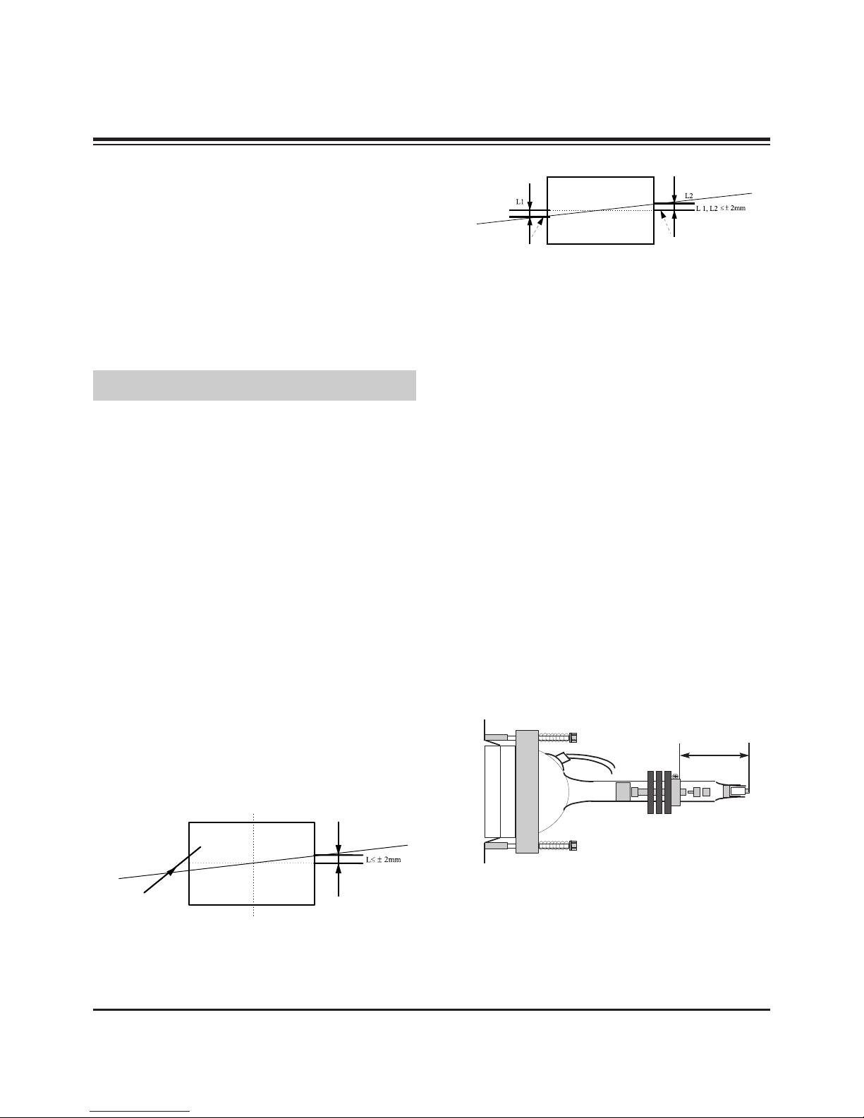
(3) Check if the Magnet is located 45mm from the end of CRT.
(4) In case of using 801GF : Receive #13 DOT Pattern of
VGA mode(Format #5) through PC input terminal.
In case of using NTSC generator : Receive Dot signal
through the external input terminal.
2-3. 2-Pole Magnet Adjustment
(1) Make Green raster by covering Red and Blue.
(2) Check the center position of DOT pattern on the center of
the screen after turning Green focus volume left.
- 14 -
ADJUSTMENT INSTRUCTIONS
Mechanical
Center
Green Light
Red/Blue Light
45mm
45mm
(3) Turning green focus volume right and adjust 2-Pole
magnet so the position to coincide that of item ”(2)”.
(4) Adjust not to shift the screen by turning green focus
volume clockwise and counter clockwise.
(5) If the screen shifts, readjust (2)~(4).
(6) Do the same method in Red and Blue.
2-4. Beam Shape(4 & 6-Pole Magnet)
Adjustment
(1) Do after 2-Pole magnet adjustment.
(2) Make Green raster using lens cover and turn the focus
volume right.
(3) Make the dot in the center a perfect circle using 4 & 6-Pole
magnet.
(4) Do the same method in Red & Blue.
(5) Fasten the Magnet after adjustment.
(6) Adjust focus accurately.
3. Centering Magnet Adjustment
3-1. Preliminary steps
(1) Receive the image signal.
(2) Select INSTART key on the Service Remote and then
select “0 RASTER ADJ” move the cursor or using the key
No..
(3) When selecting the adjustment mode, the convergence
resets automatically and then preparation for adjustment
complete.
3-2. Adjustment
(1) Execute adjustment of Red, Green and Blue centering
Magnet.
Locate the Green centering Magnet in middle.
(2) Application the SGS THOMSON CONVERGENCE ASSY,
adjust center of Blue image signal from the center of Green
image signal 30!3mm in order to reach this standing with
the left side, adjust center of Red image signal from the
center of Green image signal 30!3mm in order to reach
this standing with the right side
(3) After adjustment complete, exit the RASTER adjustment
mode using ENTER key and exit the SVC adjustment
mode using INSTART key.
4. High Voltage Regulation Adjustment
4-1. Test Equipment
Digital Multi-Meter(DMM)
4-2. Preliminary steps
Select INSTART key on the Remote Control and then select
“1 HIGH VOLTAGE ADJ” move the cursor or using the key
No..
(Manual adjustment : setting contrast/bright to 0 (A/V no
signal))
4-3. Adjustment
(1) Connect DMM to the P415(+), P416(-) of Deflection Board.
(2) Adjust VR401 so that the P415(+), P416(-) voltage is
21.7!0.1V. (High voltage 31.5KV)
(3) After adjustment complete, exit the High Voltage
adjustment mode using any key and exit the SVC
adjustment mode using INSTART key.
5. CUT-OFF Voltage Adjustment
5-1. Preliminary steps
(1) Select INSTART key on the Remote Control and then
select “2 SCREEN ADJ” move the cursor or using the key
No..
(2) Adjustment must be operated in a dark room (simple dark
room)
5-2. Adjustment
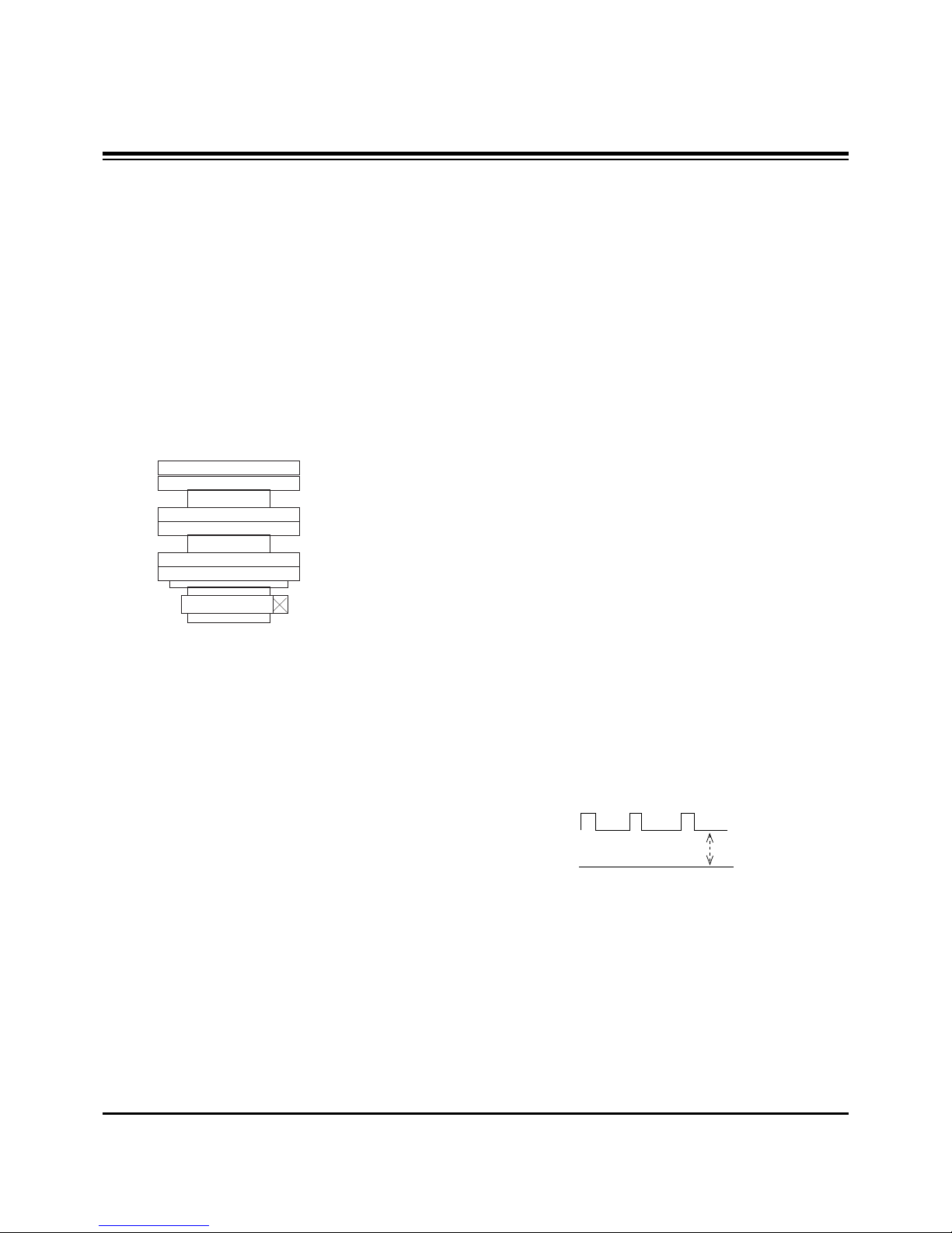
(1) Test Equipment: Oscilloscope, 100:1 Probe
(2) Connect oscilloscope to cathode of R, G, B(R926R/B/G:
SCREEN ADJ on the PCB) and GND.
(3) Turning Screen Volume (R/G/B) in Focus Pack and adjust
R/G/B is 165V!0.5V.
(4) After adjustment complete, exit the CUT-OFF adjustment
mode using ENTER key and exit the SVC adjustment
mode using INSTART key.
- 15 -
ADJUSTMENT INSTRUCTIONS
2 Pole Magnet
4 Pole Magnet
6 Pole Magnet
0V
165V±0.5V
6. Deflection Adjustment
6-1. Preliminary steps
After adjusting the NTSC first, 1080i it adjust.
6-2. NTSC Adjustment
(1) Preliminary steps
1) Select INSTART key on the Service Remote and then
select “0 RASTER ADJ” move the cursor or using the
key No..
2) Make Green raster using lens cover.
(2) Adjustment
1) Select the below each mode using CHD, CHE on the
Service Remote Control and adjust using
VOLG, VOLF.
2) Check the H POSI, V POSI is 21, 38 and When is
wrong, adjust each at corresponding price.
3) Does not adjust H, V Position in the NTSC Mode, adjust
with centering magnet.
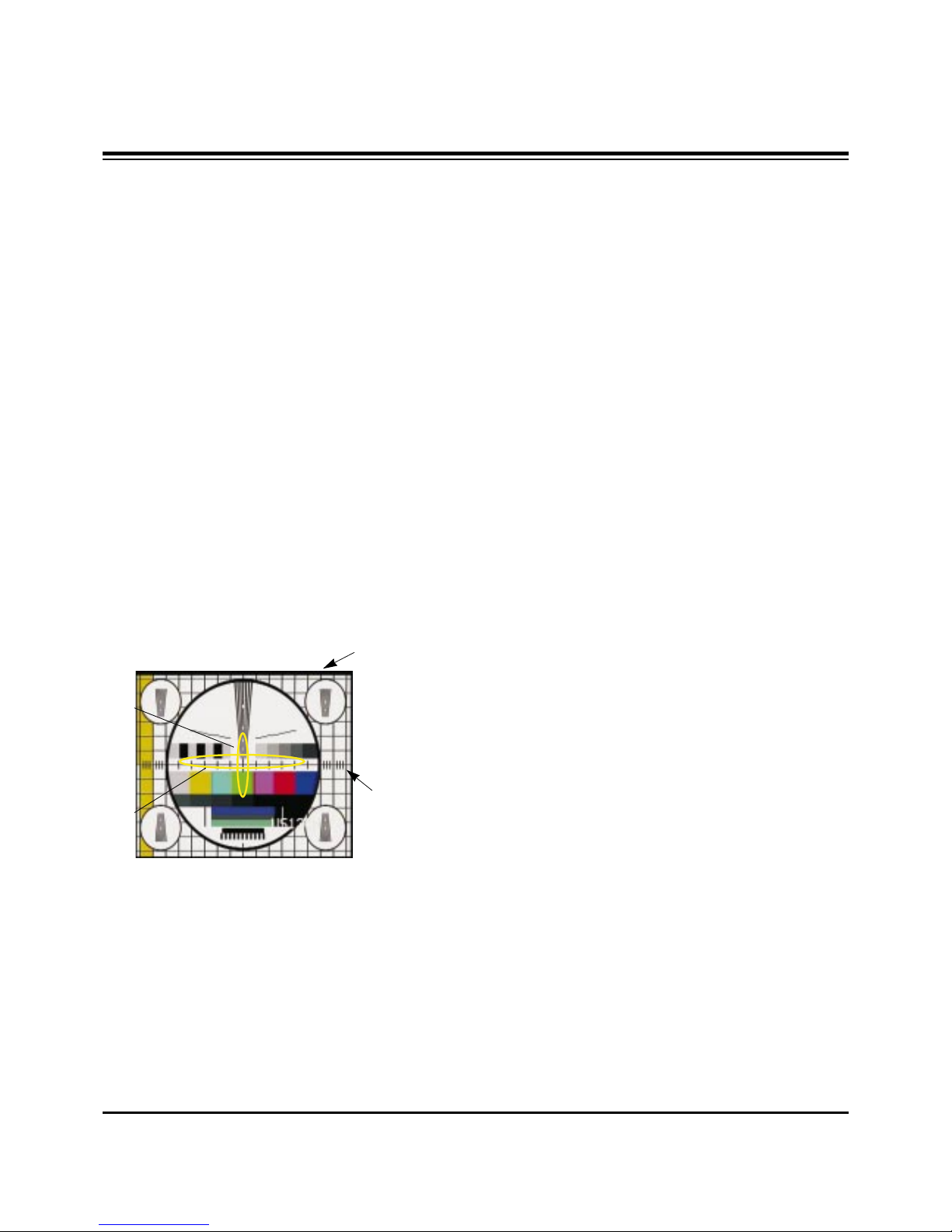
4) H SIZE : Horizontal SIZE Adjustment
Adjust until third line of circle outermost horizontal size
is accord with the edge of the frame.
5) V-SIZE : Vertical SIZE Adjustment
Adjust until fifth Vertical BAR from upper and lower
center of the screen is accord with the last point of the
frame.
6) UP VLI : Upper Vertical Linearity Adjustment
Adjust the vertical interval of screen upper.
7) LO VLI : Lower Vertical Linearity Adjustment
Adjust the vertical interval of screen lower.
8) PIN PH : Horizontal Trapezoid Fixation
Adjust the horizontal width of screen upper and lower is
to be same.
9) PIN AM : Horizontal PARABOLA Correction
Adjust the vertical line of most angle lattice of right/ left
of screen to be balance with vertical line of center of
screen.
10) V LIN : Vertical Linearity Adjustment
Adjust the vertical size of the screen to be same with
upper and lower.
11) S CORR : S Correction
Adjust the each lattice width Top/Center/Bottom of
screen to be identical.
12) UP CPI : Upper Pincushion Correction
Adjust the pincushion of upper of screen
13) LO CPI : Lower Pincushion Correction
Adjust the pincushion of lower of screen
14) After adjustment complete, exit the RASTER
adjustment mode using ENTER key and exit the SVC
adjustment mode using INSTART key.
6-3. 1080i Adjustment
(1) Test Equipment
SETTOP BOX with 1080i output
(2) Preliminary steps
1) After adjust 1080i with output of the SETTOP BOX,
connects the Y signal which is output from SETTOP
BOX with the VIDEO input terminal of the SIDEAV(AV3).
2) Select INSTART key on the Remote Control and then
select “8 1080I-ADJ” move the cursor or using the key
No..
Connected to AV3 is 1080i the black/white signal
appears in the screen.
3) Select INSTART key on the Remote Control and then
select “0 RASTER ADJ” move the cursor or using the
key No..
4) Make Green raster using lens cover.
(3) Adjustment
1) Select the below each mode using CHD, CHE on the
Remote Control and adjust using VOLG, VOLF.
2) H POSI : Horizontal Position Adjustment
Adjust so that the horizontal center line of screen is in
accord with geometric horizontal center line of the
screen JIG.
3) V POSI : Vertical Position Adjustment
Adjust so that the vertical center line of screen is in accord
with geometric vertical center line of the screen JIG.
4) H SIZE : Horizontal SIZE Adjustment
Adjust until third line of circle outermost horizontal size
is accord with the edge of the frame.
- 16 -
ADJUSTMENT INSTRUCTIONS
Fig. 3
Fifth Vertical BAR
Third line
- 17 -
5) V-SIZE : Vertical SIZE Adjustment
Adjust until fifth Vertical BAR from upper and lower
center of the screen is accord with the last point of the
frame.
6) UP VLI : Upper Vertical Linearity Adjustment
Adjust the vertical interval of screen upper.
7) LO VLI : Lower Vertical Linearity Adjustment
Adjust the vertical interval of screen lower.
8) PIN PH : Horizontal Trapezoid Fixation
Adjust the horizontal width of screen upper and lower is
to be same.
9) PIN AM : Horizontal PARABOLA Correction
Adjust the vertical line of most angle lattice of right/ left
of screen to be balance with vertical line of center of
screen.
10) V LIN : Vertical Linearity Adjustment
Adjust the vertical size of the screen to be same with
upper and lower.
11) S CORR : S Correction
Adjust the each lattice width Top/Center/Bottom of
screen to be identical.
12) UP CPI : Upper Pincushion Correction
Adjust the pincushion of upper of screen
13) LO CPI : Lower Pincushion Correction
Adjust the pincushion of lower of screen
14) After adjustment complete, exit the RASTER
adjustment mode using ENTER key and exit the SVC
adjustment mode using INSTART key.
7. Lens Focus and Electric Focus
Adjustment
7-1. Preliminary steps
(1) Electric focus,Raster slope & Raster position must be pre-
adjusted.
(2) Heat-run over 45 minutes.
(3) Tune the TV set to receive Cross Hatch
(4) Adjustment must be operated in a dark room(simple dark
room) and pay attention not to touch the lens during
adjustment.
(5) Make any one color raster using lens cover.
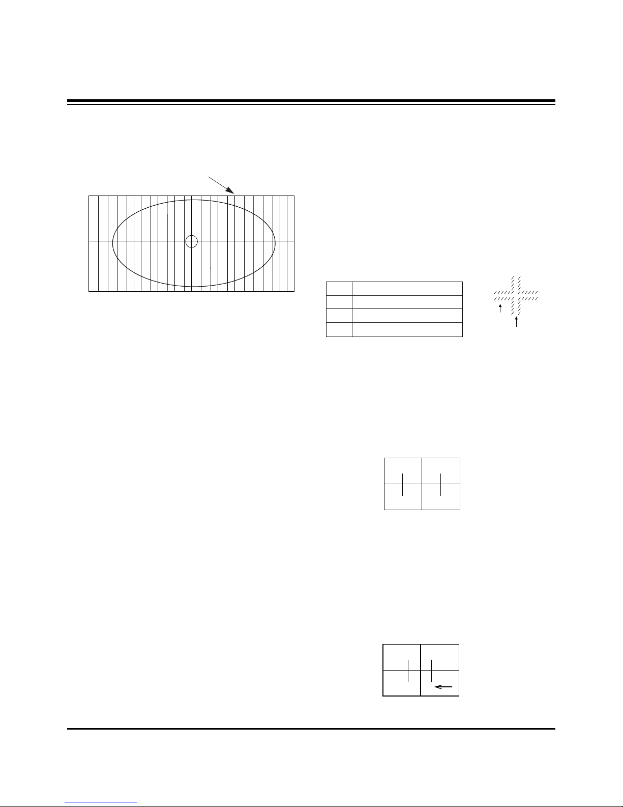
(6) Rotating lens right from the front side chromatic aberration
occurs beside Cross-hatch line changes as follows;.
7-2. Green Lens Adjustment
(1)Turn the lens until the chromatic aberration changed Blue
to Red point.
(2) Observing all screen, if the tendency of chromatic
aberration is non-linear, adjust to appear Red chromatic
aberration in 3.5 Cross-Hatch section at center screen.
At this time, in case that the difference of bright line of Red
chromatic aberration is not equal at both sides, adjust to
have more Red chromatic aberration.
(3)Switching the signal to 13CH and operate adjustment
minutely.
(4)Adjust Green focus control volume of focus pack so that
the external big circle's part appeared cleary.
(5) Adjust accurately by repeat the upper control.
(6) Especially, noting to the Green light because it influenced
on picture's function.
7-3. Red Lens Adjustment
(1) Turn the lens until the chromatic aberration changed
orange to scarlet.
(2) Adjust the chromatic aberration so it is centered correctly.
(3) Use the same method for the Red focus as was used for
the Green focus.
ADJUSTMENT INSTRUCTIONS
CHROMATIC
ABERRATION
CROSS HATCH
SIGNAL
Lens
Red
Green
Blue
Change of chromatic aberration
Orange $ Scarlet
Blue
$ Red
Purple
$ Green
Fig. 3
Fifth Vertical BAR
- 18 -
ADJUSTMENT INSTRUCTIONS
7-4. Blue Lens Adjustment
(1) Rotate the lens until the chromatic abberration of 3.5
Cross-Hatch left from center point changes from Violet to
Green. Adjust the chromatic abberration to be center point
between violet and green.
(2) Adjust the chromatic aberration become center of purple
and green.
(3) Use the same method for the Blue focus as was used for
the Green focus.
7-5. After adjustment Red, Green & Blue lens, remove lens
cover and receive Cross-Hatch pattern and check the
overall focus. If need, repeat above.
8. Convergence Adjustment
Execute the convergence adjustment in NTSC MODE and
1080i MODE and each method does with method lower part.
NTSC Mode : Adjust in CH13.
1080i Mode : Adjust the Y signal which is output from the
SETTOP BOX after putting in in the AV3. (Refer to deflection
adjustment)
8-1. Preliminary steps
(1)This adjustment should be performed after warming up 60
minutes.
(2)This adjustment should be performed after vertical
/horizontal raster position, beam alignment magnet and
focus adjustment.
(3)Always apply a signal during this adjustment.
(4) Adjust uses the JIG screen which is lattice pattern.
8-2. Adjustment
(1) Select INSTART key on the Remote Control and then
select “3 CONVERGENCE” move the cursor or using the
key No..
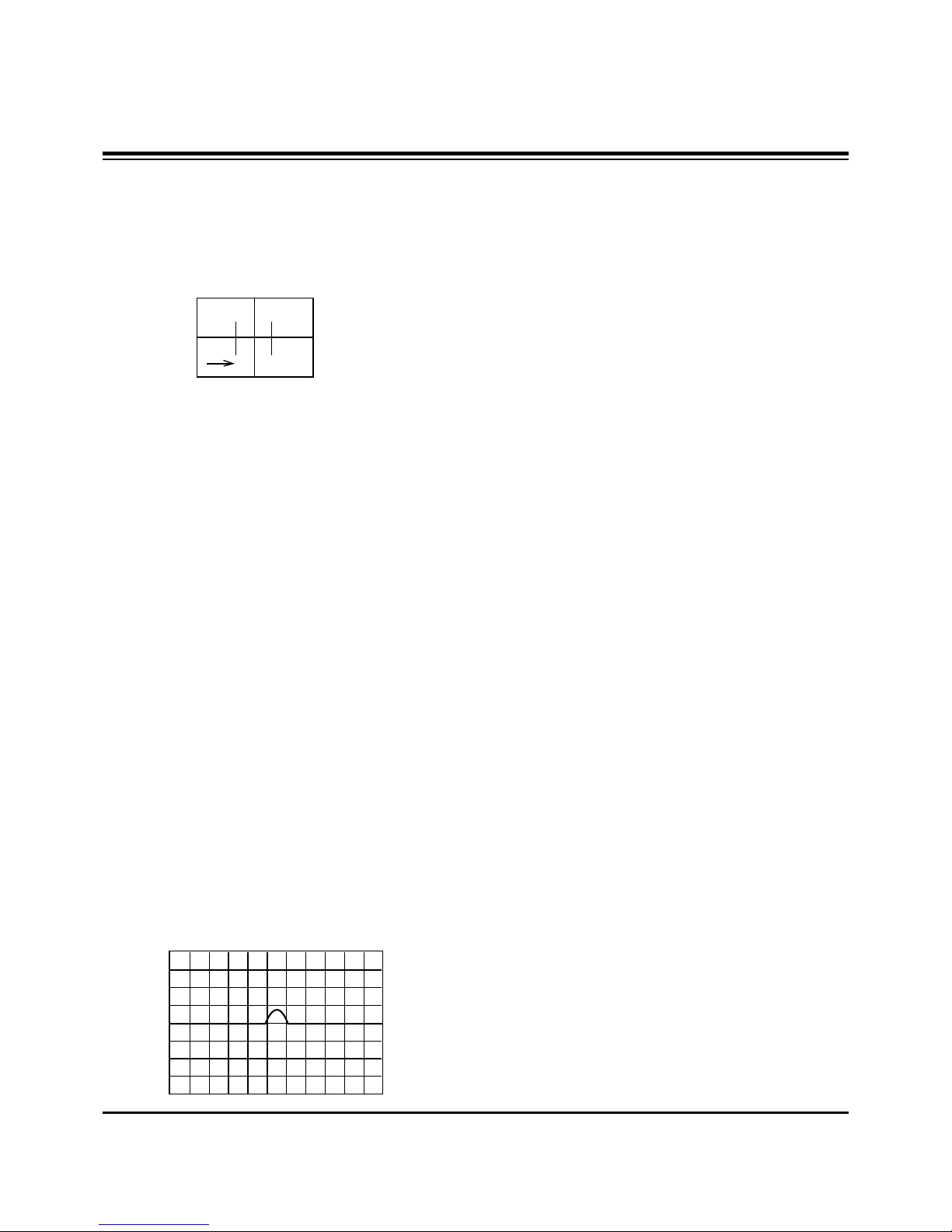
(2)Horizontal/Vertical phase Adjustment
1) Press the button 9 & 5 to get into the phase adjustment
mode.
2) Horizontal phase Adjustment : Move the convex portion
to the middle of TV screen. Adjust the right and left
height of second lattice into same height.
(Using the F, G buttons)
(3) Horizontal Pattern Position Adjustment
1) Press the button 9 & 4 to get into the pattern shift mode.
2) Adjust the pattern and image to be pile up by pressing
the MUTE key.
3) Adjust the center of pattern and image to be agree.
(Using the F,G,D,E buttons)
4) Use the (ENTER) button to exit this adjustment.
5) To save the adjustment data press 9, 2 then ENTER.
(4) Convergence Automatic Adjustment
Convergence adjust uses the PC and Camera
automatically in basic, after automatic adjusting against the
portion where the Convergence is not right with lower part
manually adjustment with same method.
(5) Green Convergence Adjustment (manually)
1) After the OSD to appear in the screen by pressing key
No. 2, change with green(G) adjustment mode by
pressing TV/AV.
2) Display green color only on the screen by corvering to
red CRT and blue CRT.
3) Adjust to coincide green pattern with screen jig pattern.
(Using the F,G,D,E buttons)
At this time, Move cursor from center screen to around
screen and adjust convergence.
(6) Red Convergence Adjustment (manually)
1) After the OSD to appear in the screen by pressing key
No. 2, change with red(R) adjustment mode by
pressing TV/AV.
2) If you need, cover the Blue lens.
3) Coincide the red screen with green screen in same way
with that of green convergence adjustment.
(7) Blue Convergence Adjustment (manually)
1) After the OSD to appear in the screen by pressing key
No. 2, change with blue(B) adjustment mode by
pressing TV/AV.
2) Coincide the blue screen with green screen in same way
with that of green convergence adjustment.
(8) Adjusted Data Saving (manually)
1) Save the data after adjustment by pressing 9, 1, and
ENTER key.
2) Quit convergence adjustment mode.
(Using the INSTART key)

8-3. Inicializing of AUTO CONVERGENCE
(1) Select INSTART key on the Remote Control and then
select “3 CONVERGENCE” move the cursor or using the
key No..
(2) Press MENU key and then select ‘3.AC POSITION MES.’.
(3) When adjusted normally, “OK” will appear on the center of
screen. When finishing the adjustment, quit Convergnece
adjustment mode.
(Using the ENTER and INSTART buttons)
9. White Balance Adjustment
9-1. Test Equipment
Brightness meter(CA-110)
9-2. Preliminary steps
(1) Adjust after Screen and Focus adjustment has been
completed.
(2) This adjustment must be operated in a dark room or
equivalent.
(3) The brightness meter must be located in 20!5cm distance
from the center of the screen.
(4) Set the BURST OUT Setting of PATTERN GENERATER
is OFF.
9-3. Adjustment(manually)
(1) Select INSTART key on the Remote Control and then
select “4 WHITE BALANCE” move the cursor or using the
key No..
(2) Receive the WINDOW signal. (NTSC 13CH)
1) After enter the adjustment mode using INSTART key,
select “4 WHITE BALANCE” of adjustment mode.
2) High Light=160±3cd/m
2
Low Light=10±3cd/m
2
(3) Set Bright to H/Light adjustment mode in (2) and adjust R-
DRIVE, B-DRIVE until color coordinate becomes X=269±3,
Y=274±3.
Warm : X=313±3, Y=320±3.
Normal : X=295±3, Y=305±3.
Cool: X=277±3, Y=280±3.
(4) Set Bright to L/Light adjustment mode in (2) and adjust R-
CUTOFF, B-CUTOFF until color coordinate becomes
X=269±3, Y=274±3.
Warm : X=313±3, Y=320±3.
Normal : X=295±3, Y=305±3.
Cool: X=277±3, Y=280±3.
(5) After adjustment complete, exit the RASTER adjustment
mode using ENTER key and exit the SVC adjustment
mode using INSTART key.
10. SUB-BRIGHTNESS Adjustment
(Only NTSC Mode)
(1) Select NTSC CH14.
(2) Select INSTART key on the Remote Control and then
select “5 SUB-BRIGHTNESS” move the cursor or using
the key No..
When select “5 SUB-BRIGHTNESS” mode after entering
adjustment mode with INSTART key, then preparation for
adjustment complete.
(3) Adjust until the “2” disappear. (Using the VOL F, G)
(4) After adjustment complete, exit the RASTER adjustment
mode using ENTER key and exit the SVC adjustment
mode using INSTART key.
- 19 -
ADJUSTMENT INSTRUCTIONS
01 2 3 4 5 6 7 8 9
US14CH
 Loading...