


SYSTEM 3 SY2738RK
Zenith SYSTEM 3 SY2738RK, SYSTEM 3 SY3538RK, System 3 SY2738, System 3 SY2739, System 3 SY2779 Operating Manual & Warranty
...
THEQUALITY GOES IN BEFORETHE NAME GOES ON
Return the
Product
Registration
Card and your
TV could be
n!
:ros
ue
tanual!
SAFETY WARNINGS
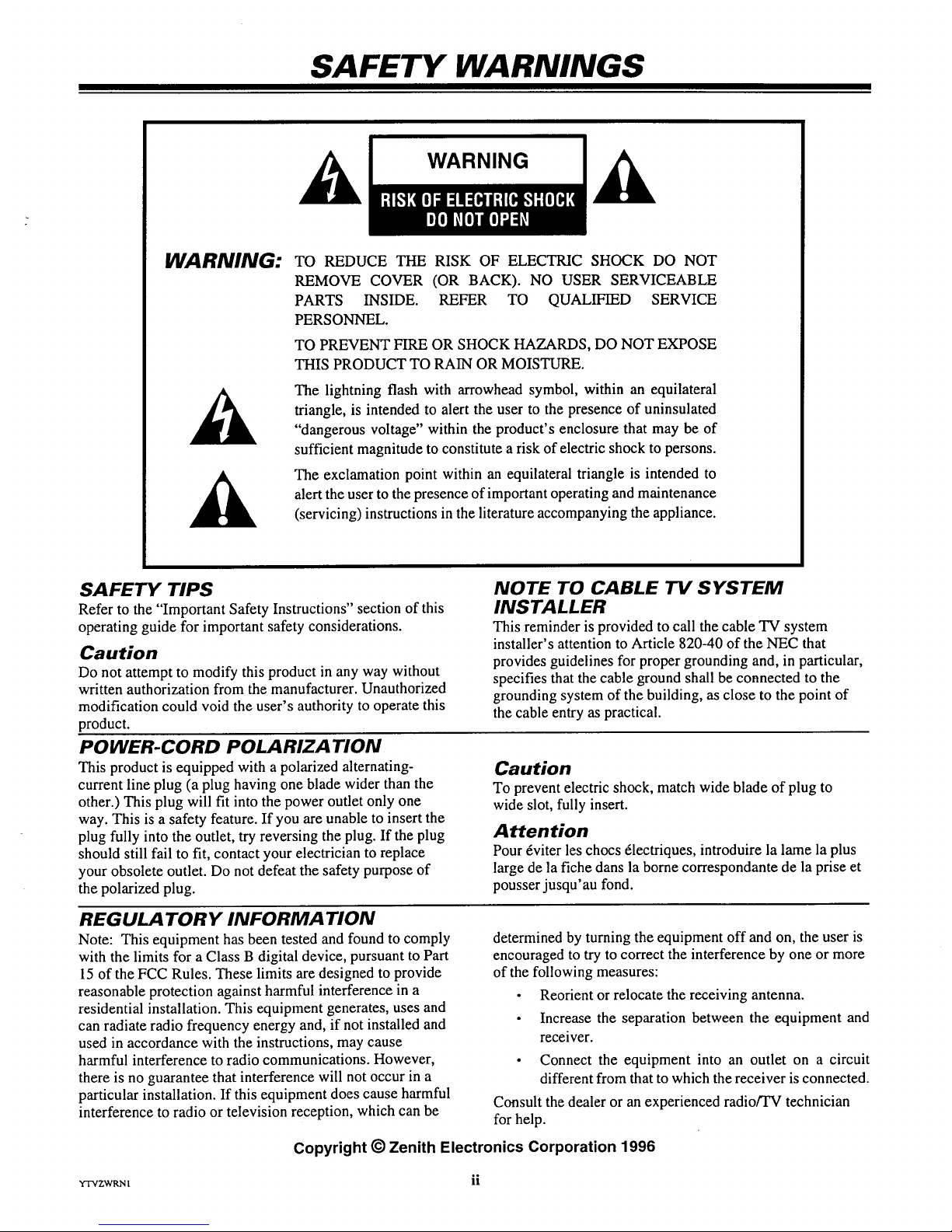
WARNING:
WARNING
TO REDUCE THE RISK OF ELECTRIC SHOCK DO NOT
REMOVE COVER (OR BACK). NO USER SERVICEABLE
PARTS INSIDE. REFER TO QUALIFIED SERVICE
PERSONNEL.
TO PREVENT FIRE OR SHOCK HAZARDS, DO NOT EXPOSE
THIS PRODUCT TO RAIN OR MOISTURE.
The lightning flash with arrowhead symbol, within an equilateral
triangle, is intended to alert the user to the presence of uninsulated
"dangerous voltage" within the product's enclosure that may be of
sufficient magnitude to constitute a risk of electric shock to persons.
The exclamation point within an equilateral triangle is intended to
alert the user to the presence of important operating and maintenance
(servicing) instructions in the literature accompanying the appliance.
SAFETY TIPS
Refer to the "Important Safety Instructions" section of this
operating guide for important safety considerations.
Caution
Do not attempt to modify this product in any way without
written authorization from the manufacturer. Unauthorized
modification could void the user's authority to operate this
product.
POWER-CORD POLARIZATION
This product is equipped with a polarized alternating-
current line plug (a plug having one blade wider than the
other.) This plug will fit into the power outlet only one
way. This is a safety feature. If you are unable to insert the
plug fully into the outlet, try reversing the plug. If the plug
should still fail to fit, contact your electrician to replace
your obsolete outlet. Do not defeat the safety purpose of
the polarized plug.
NOTE TO CABLE TV SYSTEM
INSTALLER
This reminder is provided to call the cable TV system
installer's attention to Article 820-40 of the NEC that
provides guidelines for proper grounding and, in particular,
specifies that the cable ground shall be connected to the
grounding system of the building, as close to the point of
the cable entry as practical.
Caution
To prevent electric shock, match wide blade of plug to
wide slot, fully insert.
Attention
Pour _viter les chocs 61ectriques, introduire la lame la plus
large de la fiche dans la borne correspondante de la prise et
pousser jusqu'au fond.
REGULA TORY INFORMATION
Note: This equipment has been tested and found to comply
with the limits for a Class B digital device, pursuant to Part
15 of the FCC Rules. These limits are designed to provide
reasonable protection against harmful interference in a
residential installation. This equipment generates, uses and
can radiate radio frequency energy and, if not installed and
used in accordance with the instructions, may cause
harmful interference to radio communications. However,
there is no guarantee that interference will not occur in a
particular installation. If this equipment does cause harmful
interference to radio or television reception, which can be
determined by turning the equipment off and on, the user is
encouraged to try to correct the interference by one or more
of the following measures:
• Reorient or relocate the receiving antenna.
• Increase the separation between the equipment and
receiver.
• Connect the equipment into an outlet on a circuit
different from that to which the receiver is connected.
Consult the dealer or an experienced radio/TV technician
for help.
Copyright © Zenith Electronics Corporation 1996
rrvzwRNI ii
IMPORTANT SAFETY INSTRUCTIONS
Your product has been manufactured and tested with your safety in mind. However, improper use can result in potential electrical
shock or fire hazards. To avoid defeating the safeguards that have been built into your new product, please read and observe the
following safety points when installing and using your new product, and save them for future reference.
Observing the simple precautions discussed in this section of the operating guide can help you get many years of enjoyment and
safe operation that are built into your new product.
1. Read Instructions
All the safety and operating instructions should be
read before the product is operated.
2. Follow Instructions
All operating and use instructions should be fol-
lowed.
,
.
Retain Instructions
The safety and operating instructions should be re-
tained for future reference.
Heed Warnings
All warnings on the product and in the operating in-
structions should be adhered to.
5. Cleaning
Unplug this product from the wall outlet before
cleaning. Do not use liquid cleaners or aerosol
cleaners. Use a damp cloth for cleaning.
6. Water and Moisture
Do not use this product near water -- for example,
near a bath tub, wash bowl, kitchen sink, or laundry
tub, in a wet basement, or near a swimming pool.
7. Accessories
Do not place this product on an unstable cart,
stand, tripod, bracket, or table. The product may
fall, causing serious injury to a child or adult, and
serious damage to the product. Use only with a
cart, stand, tripod, bracket, or tablerecommended
by the manufacturer, or sold with the product. Any
mounting of the product should follow the manufac-
turer's instructions, and should use a mounting
accessory recommended by the manufacturer.
8. Transporting Product
A product and cart combination should be moved
with care. Quick stops, excessive force, and uneven
surfaces may cause the product and cart combina-
tion to overturn.
PORTABLE CART WARNING
9. Attachments
Do not use attachments not recommended by the
product manufacturer as they may cause hazards.
10. Ventilation
Slots and openings in the cabinet are provided for
ventilation and to ensure reliable operation of the
product and to protect it from overheating, and
these openings must not be blocked or covered. The
openings should never be blocked by placing the
product on a bed, sofa, rug, or other similar sur-
face. This product should not be placed in a built-in
installation such as a bookcase or rack unless
proper ventilation is provided or the manufacturer's
instructions have been adhered to.
11. Power Sources
This product should be operated only from the type
of power source indicated on the marking label. If
you are not sure of the type of power supply to
your home, consult your product dealer or local
power company. For products intended to operate
from battery power, or other sources, refer to the
operating instructions.
12. Line-Cord Polarization __
This product is equipped with a polarized alternat-
ing-current line plug (a plug having one blade
wider than the other). This plug will fit into the
power outlet only one way. This is a safety feature.
If you are unable to insert the plug fully into the
outlet, try reversing the plug. If the plug should
still fail to fit, contact your electrician to replace
your obsolete outlet. Do not defeat the safety pur-
pose of the polarized plug.
13. Power-Cord Protection
Power-supply cords should be routed so that they
are not likely to be walked on or pinched by items
placed upon or against them, paying particular at-
tention to cords at plugs, convenience receptacles,
and the point where they exit from the product.
°,°
YSAFEI 111

IMPORTANT SAFETY INSTRUCTIONS
14.
Outdoor Antenna Grounding
If an outside antenna or cable system is connected
to the product, be sure the antenna or cable system
is grounded so as to provide some protection
against voltage surges and built-up static charges.
Article 810 of the National Electrical Code
(U.S.A.), ANSI/NFPA 70 provides information
with regard to proper grounding of the mast and
supporting structure, grounding of the lead-in wire
to an antenna discharge unit, size of grounding con-
ductors, location of antenna-discharge unit,
connection to grounding electrodes, and require-
ments for the grounding electrode.
EXAMPLE OF GROUNDING ACCORDING TO
NATIONAL ELECTRICAL CODE INSTRUCTIONS
Ground_ Antenna Lead in Wire
Antenna Discharge Unit
(NEC Section 810-20)
Grounding Conductors
(NEC Section 810-21)
Ground Clamps
Power Service Grounding
_'.-._= I __ Electrode System (NEC
Art 250, Part H)
NEC - NATIONAL ELECTRICAL CODE
15. Lightning
For added protection for this product (receiver) dur-
ing a lightning storm, or when it is left unattended
and unused for long periods of time, unplug it from
the wall outlet and disconnect the antenna or cable
system. This will prevent damage to the product
due to lightning and power-line surges.
16. Power Lines
An outside antenna system should not be located in
the vicinity of overhead power lines or other elec-
tric light or power circuits, or where it can fall into
such power lines or circuits. When installing an out-
side antenna system, extreme care should be taken
to keep from touching such power lines or circuits
as contact with them might be fatal.
17. Overloading
Do not overload wall outlets and extension cords as
this can result in a risk of fire or electric shock.
18. Object and Liquid Entry
Never push objects of any kind into this product
through openings as they may touch dangerous volt-
age points or short-out parts that could result in a
fire or electric shock. Never spill liquid of any kind
on the product.
19. Servicing
Do not attempt to service this product yourself as
opening or removing covers may expose you to dan-
gerous voltage or other hazards. Refer all servicing
to qualified service personnel.
20. Damage Requiring Service
Unplug this product from the wall outlet and refer
servicing to qualified service personnel under the
following conditions:
a. If the power-supply cord or plug is damaged.
b. If liquid has been spilled, or objects have fallen
into the product.
c. If the product has been exposed to rain or water.
d. If the product does not operate normally by fol-
lowing the operating instructions. Adjust only
those controls that are covered by the operating
instructions as an improper adjustment of other
controls may result in damage and will often re-
quire extensive work by a qualified technician
to restore the product to its normal operation.
e. If the product has been dropped or the cabinet
has been damaged.
f. If the product exhibits a distinct change in per-
formance.
21. Replacement Parts
When replacement parts are required, be sure the
service technician has used replacement parts speci-
fied by the manufacturer or have the same
characteristics as the original part. Unauthorized
substitutions may result in fire, electric shock, or
other hazards.
22. Safety Check
Upon completion of any service or repairs to this
product, ask the service technician to perform
safety checks to determine that the product is in
proper operating condition.
23. Wall or Ceiling Mounting
The product should be mounted to a wall or ceiling
only as recommended by the manufacturer.
24. Heat
The product should be situated away from heat
sources such as radiators, heat registers, stoves, or
other products (including amplifiers) that produce
heat.
YSAFEI iv
CONTENTS
SAFETY WARNINGS
SAFETY TIPS
INTRODUCTION
Welcome .............................................. vi
Installation Considerations ................................ vi
STANDARD CONNECTIONS FOR YOUR TV
Connection Center ..................................... 1--1
Connection Options .................................... 1-=-1
GET TO KNOW THE TV'S CONTROL PANEL
Control Panel ......................................... 2--1
Basic Menu Operation Using the Control Panel .............. 2--1
WHAT YOU SHOULD DO FIRST
Connect The Power .................................... 3--1
Install The Batteries IntoThe Remote Control ............... 3--1
Get To Know Remote Control Basic Menu Operation ......... 3--1
Select Your Language ................................... 3--2
Use Auto Program ..................................... 3--2
Set The Clock in the TV ................................ 3--2
Use Other Menu Options ................................ 3--2
Optional Auto Demo Feature ............................ 3--2
GEM4000 VCR PLUS+C3® REMOTE CONTROL
TV Mode Functions .................................... 4--1
Install the Batteries .................................... 4---2
Programming CABLE, VCR, and AUX Modes .............. 4---2
Auto Find Option ...................................... 4---2
Cable Box Volume Muting .............................. 4---2
Set The Clock in the Remote Control ...................... 4--3
Special Features Codes ................................. 4---3
Key Functions for Zenith Modes .......................... 4--4
Equipment Codes ..................................... 4---5
VCR Plus+ Mode Key Functions ......................... 4---6
VCR Plus+ Channel Mapping ............................ 4---7
VCR Plus+ Recording .................................. 4--9
Troubleshooting ...................................... 4--10
QUICK REFERENCE TO ON-SCREEN MENUS
Available Menus ...................................... 5--1
Basic Menu Operation .................................. 5--1
SETUP MENU
Menu Operation ....................................... 6---1
Using Add/Del/Surf .................................... 6---2
Using Channel Labels .................................. 6---2
Timer Setup: Sleep Timer ............................... 6---2
Timer Setup: On/Off Timer .............................. 6---3
Using Parental Control ................................. 6---3
AUDIO MENU
Menu Operation ....................................... 7--1
VIDEO MENU
Menu Operation ....................................... 8--1
PIP MENU
Menu Operation ....................................... 9--1
SOURCE MENU
Menu Operation ...................................... 10--1
PIP CONNECTIONS AND OPERATION
Introduction ......................................... 11--1
PIP Functions ........................................ I 1--1
Basic Picture-In-Picture Operation ....................... 11--2
Optional Picture-In-Picture Operation .................... 11--3
MAINTENANCE AND TROUBLESHOOTING
Caring For Your TV .................................. 12--I
Extended Absence ................................... 12--1
TV Picture Interference ................................ 12--1
Before Calling For Service ............................. 12--2
RECOMMENDED ACCESSORIES
REPLACEMENT PRODUCT REGISTRATION CARD
AVISO PARA NUESTROS CLIENTES DE HABLA HISPANA
YOUR ZENITH WARRANTY
FEATURES PROVIDED WITH YOUR "IV
This operating guide describes a family of TV models. Not all models have all of the features described in this guide. Different control panels
may be used from model to model. Most models include the following features:
• On-Screen Menus Accessed By Remote or TV Controls
• Picture-In-Picture
• VCR Plus Recording Multi-Brand Programmable Remote
• Parental Control
• MTS Stereo
• Front Channel Surround Sound
• Closed Caption and Text Modes
• Channel Labels for Easy Channel Identification
• Sleep Timer and On/OffTimer
• Automatic Channel Programming
• English/Spanish/French On-Screen Menus
• Audio/Video Input Jacks for Stereo VCR
• 181 Channel Tuning, STD/HRC/ICC Bands
• Antenna/Cable Input Jack
• Variable Audio Output Jacks
• SoundRiteSound Control
(Design and specifications are subject to change without prior notification.)
3130-0 V
INTRODUCTION
WELCOME
Welcome into the family of Zenith Color Television owners.
This guide provides instructions on how to operate your new
TV. In addition, we strongly advise you to read and observe
the precautions listed in the Safety Tips section of this operat-
ing guide. Read this publication carefully so that you will re-
ceive full enjoyment from your new Zenith TV for many years
to come.
Your new TV has been designed and built to give you the very
best in quality, features and performance. There are many re-
gional Zenith authorized service centers throughout the U.S.,
Canada and Mexico who can attend promptly and effectively
to ordinary service needs.
If you should have an unusual performance or service problem
that cannot be satisfactorily resolved by your Zenith authorized
service center, call or write:
Zenith Electronics Corporation
Customer Service Department
1000 Milwaukee Avenue
Glenview, IL 60025-2493
Telephone: (847) 391-8752
Mon-Fri, 8:00 a.m. - 4:30 p.m. Central Time
Send the model number, serial number, and date of purchase
or original installation, with a full explanation of the problem
and the service history. We will welcome the opportunity to
look into your specific question or problem and to be of assis-
tance in resolving it promptly.
The model and serial numbers of your new TV are located on the
back of the TV cabinet. For your future convenience and protec-
tion, we suggest that you record these numbers here:
Model No.
Serial No.
INSTALLATION CONSIDERATIONS
Before you install your TV...
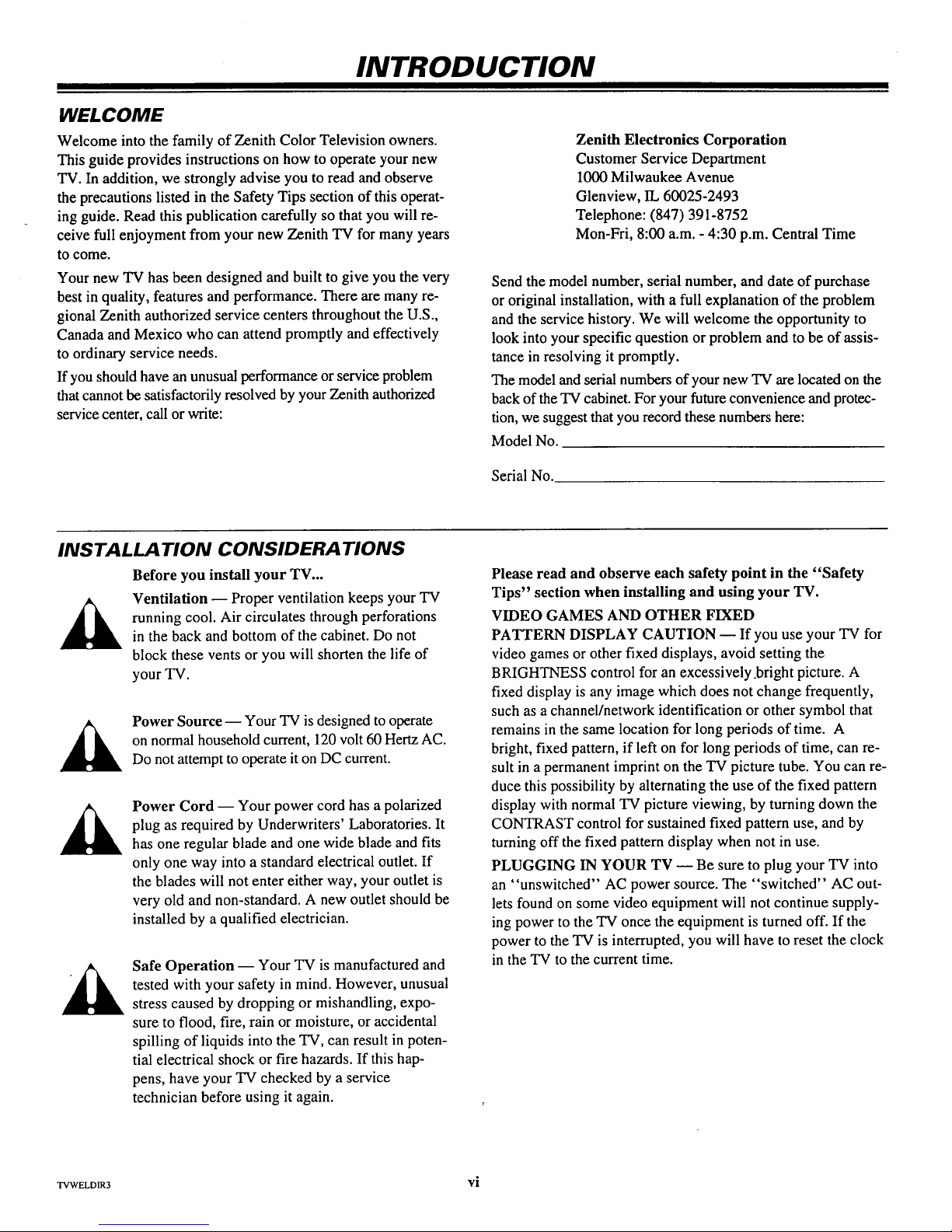
Ventilation -- Proper ventilation keeps your TV
running cool. Air circulates through perforations
in the back and bottom of the cabinet. Do not
block these vents or you will shorten the life of
your TV.
Power Source -- Your TV is designed tooperate
on normal household current, 120 volt 60 Hertz AC.
Do not attempt to operate it on DC current.
Power Cord -- Your power cord has a polarized
plug as required by Underwriters' Laboratories. It
has one regular blade and one wide blade and fits
only one way into a standard electrical outlet. If
the blades will not enter either way, your outlet is
very old and non-standard. A new outlet should be
installed by a qualified electrician.
Safe Operation -- Your TV is manufactured and
tested with your safety in mind. However, unusual
stress caused by dropping or mishandling, expo-
sure to flood, fire, rain or moisture, or accidental
spilling of liquids into the TV, can result in poten-
tial electrical shock or fire hazards. If this hap-
pens, have your TV checked by a service
technician before using it again.
Please read and observe each safety point in the "Safety
Tips" section when installing and using your TV.
VIDEO GAMES AND OTHER FIXED
PATTERN DISPLAY CAUTION -- If you use your TV for
video games or other fixed displays, avoid setting the
BRIGHTNESS control for an excessively_bright picture. A
fixed display is any image which does not change frequently,
such as a channel/network identification or other symbol that
remains in the same location for long periods of time. A
bright, fixed pattern, if left on for long periods of time, can re-
sult in a permanent imprinton the TV picture tube. You can re-
duce this possibility by alternating the use of the fixed pattern
display with normal TV picture viewing, by turningdown the
CONTRAST control for sustained fixed pattern use, and by
turning off the fixed patterndisplay when not in use.
PLUGGING IN YOUR TV -- Be sure to plug yourTV into
an "unswitched" AC power source. The "switched" AC out-
lets found on some video equipment will not continue supply-
ing power to the "IV once the equipment is turned off. If the
power to the TV is interrupted, you will have to reset the clock
in the TV to the current time.
TVWELDIR3 vi
STANDARD CONNECTIONS FOR YOUR TV
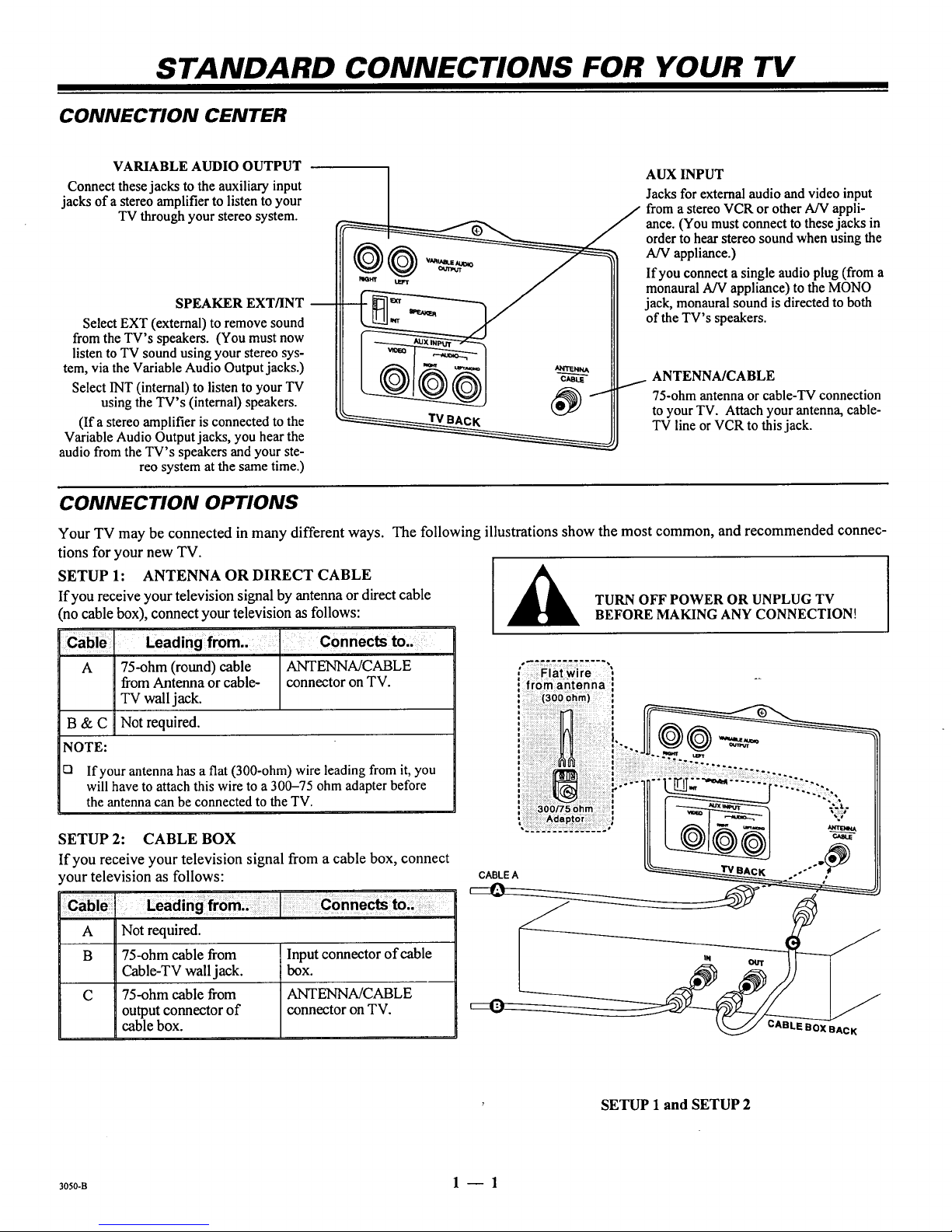
CONNECTION CENTER
VARIABLE AUDIO OUTPUT
Connect these jacks to the auxiliary input
jacks of a stereo amplifier to listen to your
TV through your stereo system.
SPEAKER EXT/INT
Select EXT (external) to remove sound
from the TV's speakers. (You must now
listen to TV sound using your stereo sys-
tem, via the Variable Audio Output jacks.)
Select INT (internal) to listen to your TV
using the TV's (internal) speakers.
(If a stereo amplifier is connected to the
Variable Audio Output jacks, you hear the
audio from the TV's speakers and your ste-
reo system at the same time.)
AUX INPUT
Jacks for external audio and video input
from a stereo VCR or other A/V appli-
ance. (You must connect to these jacks in
order to hear stereo sound when using the
AN appliance.)
If you connect a single audio plug (from a
monaural A/V appliance) to the MONO
jack, monaural sound is directed to both
of the TV's speakers.
ANTENNA/CABLE
75-ohm antenna or cable-TV connection
to your TV. Attach your antenna, cable-
TV line or VCR to this jack.
CONNECTION OPTIONS
Your TV may be connected in many different ways. The following illustrations show the most common, and recommended connec-
tions for your new TV.
SETUP 1: ANTENNA ORDIRECT CABLE
If you receive your television signal by antenna or direct cable
(no cable box), connect your television as follows:
Leading from.. Connects to..
A 75-ohm (round) cable ANTENNA/CABLE
from Antenna or cable- connector on TV.
TV wall jack.
Not required.
B&C
NOTE:
El
If your antenna has a flat (300-ohm) wire leading from it, you
will have to attach this wire to a 300-75 ohm adapter before
the antenna can be connected to the TV.
SETUP 2: CABLE BOX
If you receive your television signal from a cable box, connect
your television as follows:
A Not required.
B 75-ohm cable from
Cable-TV wall jack.
C 75-ohm cable from
output connector of
cable box.
Inputconnector of cable
box.
ANTENNA/CABLE
connector on TV.
TURN OFF POWER OR UNPLUG TV
BEFORE MAKING ANY CONNECTION!
# ..... ............ i
, Flat wire :
i .....
: from antenna :
CABLEA
' /
SETUP 1 and SETUP 2
3oso-B 1 -- 1
STANDARD CONNECTIONS FOR YOUR TV
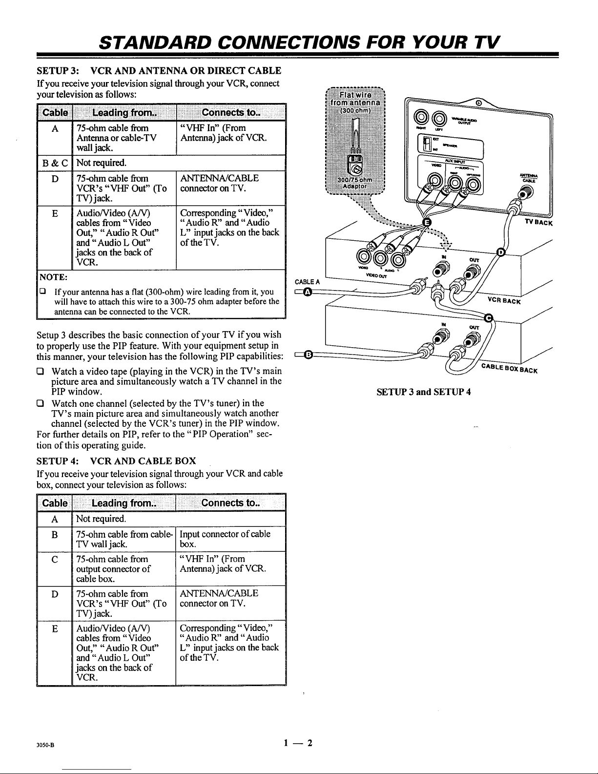
SETUP 3: VCR AND ANTENNA OR DIRECT CABLE
If you receive your television signal throughyour VCR, connect
yourtelevision as follows:
A 75-ohm cable from "VHF In" (From
Antenna orcable-TV Antenna)jack of VCR.
waUjack.
B & C Not required.
D 75-ohm cable from ANTENNA/CABLE
VCR's "VHF Out" (To connector on TV.
TV) jack.
E
Audio/Video (A/V)
cables from "Video
Out," "Audio R Out"
and "Audio L Out"
jacks on the back of
VCR.
Corresponding "Video,"
"Audio R" and "Audio
L" input jacks onthe back
of the TV.
NOTE:
D If your antenna has a flat (300-ohm) wire leading from it, you
will have to attach this wire to a 300-75 ohm adapter before the
antenna can be connected to the VCR.
Setup 3 describes the basic connection of your TV if you wish
to properly use the PIP feature. With your equipment setup in
this manner, your television has the following PIP capabilities:
Q Watch a video tape (playing in the VCR) in the TV's main
picture area and simultaneously watch a TV channel in the
PIP window.
El Watch one channel (selected by the TV's tuner) in the
TV's main picture area and simultaneously watch another
channel (selected by the VCR's tuner) in the PIP window.
For further details on PIP, refer to the "PIP Operation" sec-
tion of this operating guide.
SETUP 4: VCRAND CABLE BOX
If you receive your television signal through your VCR and cable
box, connect your television as follows:
CABLE A
SETUP 3 and SETUP 4
TVBAcK
VCR BACK
OXBAcK
A Not required.
B 75-ohm cable from cable- Input connector of cable
TV wall jack. box.
C 75-ohm cable from "VHF In" (From
output connector of Antenna) jack of VCR.
cable box.
D 75-ohm cable from ANTENNA/CABLE
VCR's "VHF Out" (To connector on TV.
TV) jack.
E
Audio/Video (A/V)
cables from "Video
Out," "Audio R Out"
and "Audio L Out"
jacks on the back of
VCR.
Corresponding "Video,"
"Audio R" and "Audio
L" inputjacks on the back
of the TV.
30so-a 1 -- 2
STANDARD CONNECTIONS FOR YOUR TV
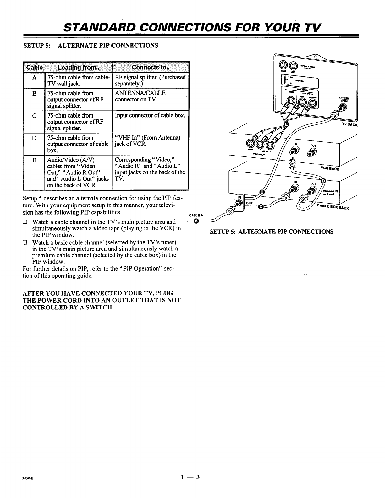
SETUP 5: ALTERNATE PIP CONNECTIONS
A 75-ohm cable from cable- RF signal splitter. (Purchased
TV wall jack. separately.)
B 75-ohm cable from ANTENNA/CABLE
output connector of RF connector on TV.
signal splitter.
C 75-ohm cable from Input connector of cable box.
output connector of RF
signal splitter.
D 75-ohm cable from "VHF In" (From Antenna)
output connector of cable jack of VCR.
box.
E
Audio/Video (A/V)
cables from "Video
Out," "Audio R Out"
and "Audio L Out" jacks
on the back of VCR.
Corresponding "Video,"
"Audio R" and "Audio L"
inputjacks on the back ofthe
TV.
Setup 5 describes an alternate connection for using the PIP fea-
ture. With your equipment setup in this manner, your televi-
sion has the following PIP capabilities:
tSI Watch a cable channel in the TV's main picture area and
simultaneously watch a video tape (playing in the VCR) in
the PIP window.
ISl Watch a basic cable channel (selected by the TV's tuner)
in the TV's main picture area and simultaneously watch a
premium cable channel (selected by the cable box) in the
PIP window.
For further details on PIP, refer to the "PIP Operation" sec-
tion of this operating guide.
CABLE A
'IV BAC
SETUP 5: ALTERNATE PIP CONNECTIONS
AFTER YOU HAVE CONNECTED YOUR TV, PLUG
THE POWER CORD INTO AN OUTLET THAT IS NOT
CONTROLLED BY A SWITCH.
30s0-B 1 -- 3
GET TO KNOW THE TV'S CONTROL PANEL
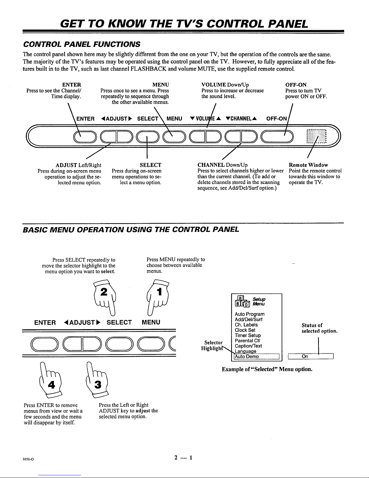
CONTROL PANEL FUNCTIONS
The control panel shown here may be slightly different from the one on your TV, but the operation of the controls are the same.
The majority of the TV's features may be operated using the control panel on the TV. However, to fully appreciate all of the fea-
tures built into the TV, such as last channel FLASHBACK and volume MUTE, use the supplied remote control.
ENTER MENU VOLUME Down/Up OFF-ON
Press to see the Channel/ Press once to see a menu. Press Press to increase or decrease Press to turn TV
Time display, repeatedly to sequence through the sound level, power ON or OFF.
the other available menus.
ENTER <ADJUSTb SELECT_MENU VV0LU/A VCHANNELA OFF-ON
/
/
ADJUST Left/Right SELECT CHANNEL Down/Up
Press during on-screen
menu operations to se-
lect a menu option.
Press during on-screen menu
operation to adjust the se-
lected menu option.
Remote Window
Press to select channels higher or lower Point the remote control
than the current channel. (To add or towards this window to
delete channels stored in the scanning operate the TV.
sequence, see Add/Del/Surf option.)
BASIC MENU OPERA TION USING THE CONTROL PANEL
Press SELECT repeatedly to
move the selector highlight to the
menu option you want to select.
ENTER
Press MENU repeatedly to
choose between available
menus.
,ADJUST), SELECT MENU
Press ENTER to remove
menus from view or wait a
few seconds and the menu
will disappear by itself.
Press the Left or Right
ADJUST key to adjust the
selected menu option.
Selector
HighlighP',,,
[_Setup Menu
Auto Program
Add/Del/Surf
Ch. Labels
Clock Set
]imer Setup
Parental Ctl
Caption/Text
Language
Auto Demo
J I
Status of
selected option.
On I
Example of "Selected" Menu option.
30s0-o 2 -- 1

WHAT YOU SHOULD DO FIRST
(_ CONNECT THE POWER
K
AFTER you have connected the necessary cable(s)to the I [_ ]
jacks on the back of the TV, plug your TV's power cord into l®
I
an AC outlet. Make sure you do not plug the TV into a [_®J
"switched" outlet (an outlet that is controlled by a switch).
m i
II
m
(_ INSTALL THE BATTERIES INTO THE REMOTE CONTROL
If you have not already installed the batteries in the remote control, now is a good time to do so. Batteries are provided, but they
must be installed before it can be used.
Unless your equipment responds to the factory preset codes, you will need to reprogram the remote control with the codes of your
9articular equipment each time you replace batteries. Refer to Remote Control "Programming Options" for details.
To install the batteries:
1. Open the battery compartment by pressing in on the tab and lift-
ing the cover off.
2. Place the batteries into the compartment matching positive with
positive (+ with +), negative with negative (- with -) with the
markings shown in the battery compartment.
3. Replace the compartment cover.
NOTES:
I=1 Do not place heavy objects on top of the remote control
keys. Prolonged unintentional operation of the remote
shortens battery life.
I=l Remove the batteries if the remote control will not be used
for amonth or more. THE REMOTE CONTROLMANUFAC-
TURERIS NOT RESPONSIBLE FOR DAMAGE CAUSED BY
BATI'ERY LEAKAGE.
_ ] Pushtab Into
JL_]_ J remove cover
Do not plug TV into switched outlet on a
VCR or cable-TV decoder
Multi-Brand Remote Control
(_ GET TO KNOW REMOTE CONTROL BASIC MENU OPERATION
Note: You can also use the TV Control Panel to select and ad-
just the on-screen menus. However, not all the TV's features
are available when using the TV Controls.
Use the remote control to access menus:
1. Point remote atTV. Press TV.
PressMENU repeatedlyto view the available menus.
Select a menu.
2. Press Up orDown arrow repeatedlytomove highlight bar to
select a menu option.
3. Use the Left or Right arrow to adjust the selected option.
4. Press QUIT to remove the menu from screen.
3130A-O 3 -- 1
 Loading...