


High Definition (HD) Satellite Receiver DTV1080
Operating Guide
and Warranty
Introduction
Important Overview
Setup and Connections
Remote Control
Initial Setup
Basic Operation
Advanced Program GuideTM
Customization
EZ Help

206-3675
|
WARNING: |
|
WARNING |
||
TO REDUCE THE RISK OF ELECTRONIC SHOCK DO NOT REMOVE COVER (OR BACK). |
||
RISK OF ELECTRIC SHOCK |
NO USER SERVICEABLE PARTS INSIDE. |
|
DO NOT OPEN |
REFER TO QUALIFIED SERVICE PERSONNEL. |
|
|
THE LIGHTNING FLASH WITH ARROWHEAD SYMBOL, WITHIN AN EQUILATERAL TRIANGLE, IS INTENDED TO ALERT THE USER TO THE PRESENCE OF UNINSULATED “DANGEROUS VOLTAGE” WITHIN THE PRODUCT’S ENCLOSURE THAT MAY BE OF SUFFICIENT MAGNITUDE TO CONSTITUTE A RISK OF ELECTRIC SHOCK TO PERSONS.
THE EXCLAMATION POINT WITHIN AN EQUILATERAL TRIANGLE IS INTENDED TO ALERT THE USER TO THE PRESENCE OF IMPORTANT OPERATING AND MAINTENANCE (SERVICING) INSTRUCTIONS IN THE LITERATURE ACCOMPANYING THE APPLIANCE.
WARNING
TO PREVENT FIRE OR SHOCK HAZARDS, DO NOT EXPOSE THIS PRODUCT TO RAIN OR MOISTURE.
NOTE TO CABLE/TV/SATELLITE DISH INSTALLER:
This reminder is provided to call the cable TV system/satellite dish installer’s attention to Article 820-40 of the National Electric Code (U.S.A). The code provides guidelines for proper grounding and, in particular, specifies that the cable ground shall be connected to the grounding system of the building, as close to the point of the cable entry as practical.
POWER CORD POLARIZATION
Caution: TO PREVENT ELECTRONIC SHOCK, MATCH WIDE BLADE OF PLUG TO WIDE SLOT, FULLY INSERT.
Attention: Pour eviter les chocs electriques, introduire la lame la plus large de la flche dans la born.
REGULATORY INFORMATION
This equipment, trade name Zenith, model number, DTV1080, has been tested and found to comply with the limits for a Class B digital device, pursuant to Part 15 of the FCC Rules. These limits are designed to provide reasonable protection against harmful interference when the equipment is operated in a residential installation. This equipment generates, uses and can radiate radio frequency energy and, if not installed and used in accordance with the instruction manual, may cause harmful interference to radio communications.
However, there is no guarantee that interference will not occur in a particular installation. If this equipment does cause harmful interference to radio or television reception, which can be determined by turning the equipment off and on, the user is encouraged to try to correct the interference by one or more of the following measures:
-Reorient or relocate the receiving antenna.
-Increase the separation between the equipment and receiver.
-Connect the equipment into an outlet on a circuit different from that to which the receiver is connected.
-Consult the dealer or an experienced radio/TV technician for help.
REGULATORY INFORMATION: FCC Part 68
•This product complies with Part 68 of the FCC rules. On the back of this product is a label that contains, among other information, the FCC registration number and Ringer Equivalent Number (REN) for this product. If requested, this information must be provided to the telephone company.
•The REN is used to determine the quantity of devices that may be connected to the telephone line. Excessive RENs on the telephone line may result in the devices not ringing in response to an incoming call. Typically, the sum of the RENs should not exceed five (5). To ve certain of the number of devices that may be connected to the line (as determined by the total RENs) contact the local telephone company.
•If this product causes harm to the telephone network, the telephone company will notify you in advance that temporary discontinuance of service may be required. But if advance notice isn’t practical, the telephone company will notify the customer as soon as possible. Also, you will be advised of your right to file a complaint with the FCC if you believe it is necessary.
•The telephone company may make changes to its facilities, equipment, operations or procedures that could affect the operation of the product. If this happens, the telephone company will provide advance notice so you can make the necessary modifications to maintain uninterrupted service.
•Connection to party line service is subject to state tariffs. (Contact the state public utility commission, public service commission, or corporate commission for information.)
•If trouble is experienced with this product, for repair or warranty information, please contact Zenith Electronics Corporation. If the product is causing harm to the telephone network, the telephone company may request that you disconnect the product until the problem is resolved.
•An FCC compliant telephone cord and modular plug is provided with this equipment. This equipment is designed to be connected to the telephone
network or premises wiring using a compatible modular jack which is Part 68 compliant. See installation instructions for details. COMPLIANCE: The responsible party for this product’s compliance is:
Zenith Electronics Corporation, 2000 Millbrook Drive, Lincolnshire, IL, 60069, USA • Phone: 1-847-391-7000
CAUTION
DO NOT ATTEMPT TO MODIFY THIS PRODUCT IN ANY WAY WITHOUT WRITTEN AUTHORIZATION FROM ZENITH ELECTRONICS CORPORATION. UNAUTHORIZED MODIFICATION COULD VOID THE USER’S AUTHORITY TO OPERATE THIS PRODUCT.
THIS EQUIPMENT IS INTENDED TO RECEIVE AND DECODE SIGNALS TRANSMITTED ACCORDING TO ATSC DIGITAL TELEVISION STANDARD A/53, DIRECTV SPECIFICATION AND IS INTENDED TO BE USED WITH AN APPROPRIATE ANTENNA, DISH AND DISPLAY DEVICE THAT YOU MUST PROVIDE.
Dolby Digital®
Manufactured under license from Dolby Laboratories.
“Dolby” and the double-D symbol are trademarks of Dolby Laboratories.
Confidential Unpublished Works. ©1992-1997 Dolby Laboratories, Inc. All rights reserved.
1

IMPORTANT SAFETY INSTRUCTIONS
1. Read Instructions
Read all of the safety and operating instructions before operating the product.
2. Retain Instructions
Keep all safety and operating instructions for future reference.
3. Heed Warnings
Follow warnings on the product and in the operating guide.
4. Follow Instructions
Follow all operating and use instructions.
5. Cleaning
Unplug this product from the wall power outlet before cleaning. Do not use liquid cleaners or aerosol cleaners. Use a damp cloth for cleaning.
6. Attachments
Do not use attachments not recommended by product manufacturer as they may cause hazards.
7. Water and Moisture
Do not use this product near water - for example, near a bathtub, wash bowl, sink, or laundry tub, in a wet basement, or near a swimming pool.
8. Accessories, Carts and Stands
Do not place this product on a slippery or tilted surface or on an unstable cart, stand, tripod, bracket, or table. The product may slide or fall, causing serious injury to a child or adult, and serious damage to the product. Use only with a cart, stand, tripod, bracket, or table recommended by the manufacturer, or sold with the product. Any mounting of the product should follow the manufacturer’s instructions, and should use a mounting accessory recommended by the manufacturer.
9. Transporting Product
Move product and cart combinations with care. Quick stops, excessive force, and uneven surfaces may cause product and cart combination to overturn.
10. Ventilation
Slots and openings in the cabinet must not be blocked or covered. They are provided for ventilation, to ensure reliable operation, and to protect from overheating. Never block openings by placing the product on a bed, sofa, rug, or other similar surface. Do not place the product in a built-in installation such as a bookcase or rack unless proper ventilation is provided or manufacturer’s instructions have been adhered to.
11. Power Sources
Operate product only from the type of power source indicated on marking label. If you are not sure of the type of power supply to your home, consult your product dealer or local power company. For products intended to operate from battery power or other sources, refer to the operating guide.
12. Power-Cord Polarization
This product is equipped with a polarized alternat- ing-current line plug (a plug having one blade wider than the other). As a safety feature, this plug will fit into the power outlet only one way. If you’re unable to insert the plug fully into the outlet, try reversing the plug. If the plug still fails to fit, contact an electrician to replace your obsolete outlet. Do not defeat the safety purpose of the polarized plug.
2
206-3675
|
Antenna Lead-in Wire |
|
Ground |
Antenna Discharge Unit |
|
Clamp |
||
NEC Section 810-20 |
||
|
||
|
Grounding Conductors |
|
Electric Service |
NEC Section 810-21 |
|
Equipment |
|
|
|
Ground Clamps |
|
|
Power Service Grounding |
|
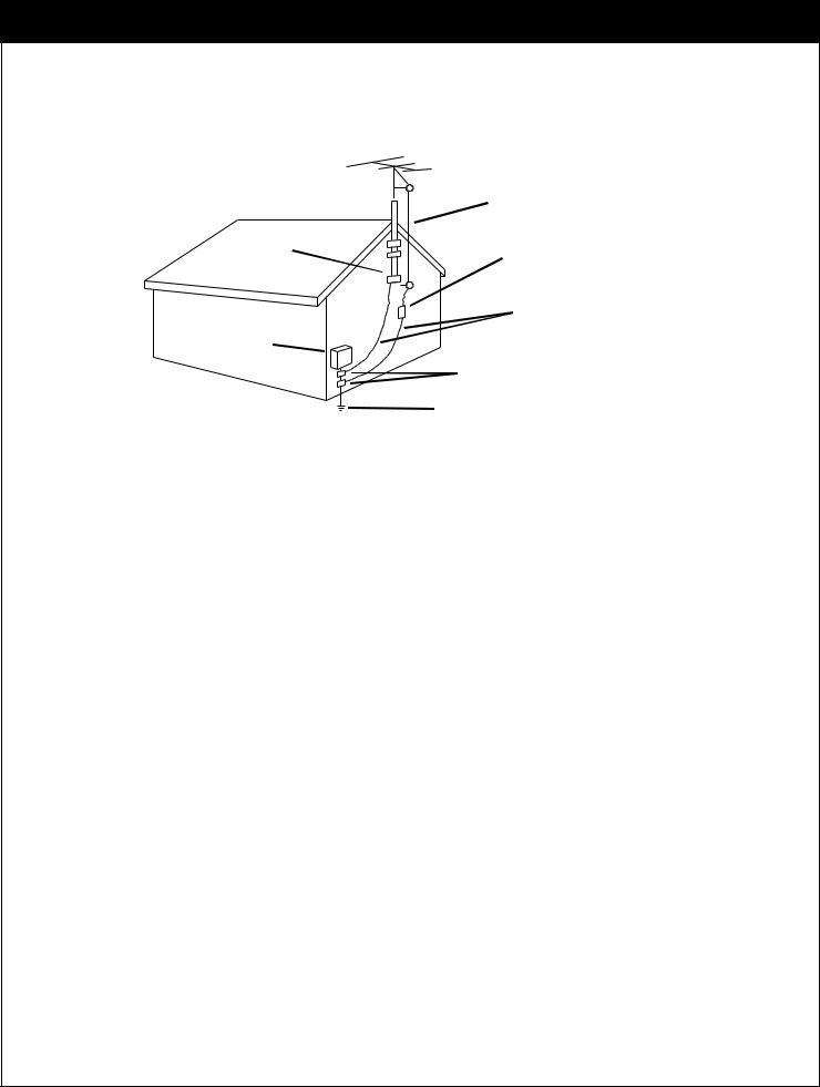
Figure. 1 |
Electrode System |
|
NEC Art 250, Part H |
13. Power-Cord Protection
Route power-supply cords so they are not likely to be walked on or pinched by items placed upon or against them, paying particular attention to cords at plugs, convenience receptacles, and the point where they exit from the product.
14. Outdoor Antenna Grounding
If an outside antenna or cable system is connected to this product, be sure the antenna or cable system is grounded so as to provide some protection against voltage surges and built-up static charges. Article 810 of the National Electrical Code (USA), ANSI/NFPA 70, provides information on grounding of the mast and supporting structure, grounding of the lead-in wire to an antenna discharge unit
connection to the grounding electrodes, and requirements for the grounding electrode. (See Figure.1 on reverse side for an example).
15. Lightning
For added protection for this product during a lightning storm, or when product is left unattended and unused for long periods of time, unplug it from the wall outlet and disconnect antenna or cable system. This will prevent damage to product due to lightning and power line surges.
206-3675
3

IMPORTANT SAFETY INSTRUCTIONS
16. Power Lines
An outside antenna system should not be located in the vicinity of overhead power lines or other electric light or power circuits, or where it can fall into such power lines or circuits. When installing an outside antenna system, take extreme care to keep from touching such power lines or circuits, as contact with them might be fatal.
17. Overloading
Do not overload wall outlets, extension cords or integral convenience receptacles, as this can result in risk of fire or electric shock.
18. Object and Liquid Entry
Never push objects of any kind into this product through openings, as they may touch dangerous voltage points or shortout parts that could result in fire or electric shock. Never spill liquid of any kind on the product.
19. Heat
Keep product away from heat sources such as radiators, heat registers, stoves, or other products (including amplifiers) that produce heat.
20. Wall or Ceiling Mounting
The product should be mounted to a wall or ceiling only as recommended by the manufacturer. The product may slide or fall, causing serious injury to a child or adult and serious damage to the product.
21. Servicing
Do not attempt to service this product yourself, as opening or removing covers may expose you to dangerous voltage or other hazards. Refer all servicing to qualified service personnel.
22. Damage Requiring Service
Unplug this product from the wall outlet and refer servicing to qualified service personnel under these conditions:
-If the power-supply cord or plug is damaged.
-If liquid has been spilled or objects have fallen into the product.
-If the product has been exposed to rain or water.
-If the product doesn’t operate normally by following the operating guide. Adjust only those controls covered by the operating guide; improper adjustment of other controls may result in damage and often requires extensive work by a qualified technician to restore the product to normal operation.
-If the product has been dropped or cabinet has been damaged.
-If the product exhibits a distinct change in performance.
23. Replacement Parts
When replacement part(s) are required, be sure service technician has used replacement part(s) specified by manufacturer or have same characteristics as original part(s).
Unauthorized substitutions may result in fire, electric shock, or other hazards.
24. Safety Check
Upon completion of any service or repairs to this product, ask service technician to perform safety checks to determine that product is in proper operating condition.
4
206-3675

IMPORTANT INFORMATION
Due to copyright restrictions, you may not be able to view some high definition programs in high definition format using this product. If HD viewing is prohibited due to copyright restrictions, you would need to connect SD interfaces to view the program.
With this receiver “Zenith DTV1080” and the proper satellite dish antenna, you may be able to subscribe to local channels from DIRECTV in certain areas. Additional equipment may be required in some markets. Check with your retailer or visit DIRECTV.com for information on availability of local channels from DIRECTV in your area.
Programming subject to change must be physically located in the U.S to receive DIRECTV service. DIRECTV services not available outside the U.S DIRECTV programming is sold separately and independently of DIRECTV System hardware. A valid programming subscription is required to operate DIRECTV System hardware. Activate your DIRECTV programming today at 1-800-DIRECTV (1-800-347-3288)
DIRECTV, the Cyclone Design logo and Advanced Program Guide are trademarks of DIRECTV, Inc., a unit of Hughes Electronics Corp., and are used with permission.
206-3675
5

TABLE OF CONTENTS
|
|
Safety Warning |
|
|
|
|
|
|
|
1 |
||||||||||||||||||||||||||
|
|
|
|
|||||||||||||||||||||||||||||||||
|
|
Important Safety Instructions |
2 |
|||||||||||||||||||||||||||||||||
|
|
Important Information |
|
|
|
|
5 |
|||||||||||||||||||||||||||||
|
|
|
|
|
||||||||||||||||||||||||||||||||
|
|
Table of Contents |
6 |
|||||||||||||||||||||||||||||||||
1. |
Introduction |
1-1. |
A New World of Digital Entertainment |
|
|
|
|
|
|
|
|
|
|
|
|
|
|
8 |
||||||||||||||||||
|
|
|
|
|
||||||||||||||||||||||||||||||||
|
|
1-2. |
Main Features |
9 |
||||||||||||||||||||||||||||||||
2. |
Important Overview |
2-1. |
Sending Signals |
|
|
|
|
|
|
|
|
|
|
|
|
|
|
|
|
|
|
|
|
|
|
|
|
|
10 |
|||||||
|
|
|
|
|||||||||||||||||||||||||||||||||
|
|
2-2. |
TV Signal Formats |
11 |
||||||||||||||||||||||||||||||||
|
|
2-3. |
Normal and Wide Format Signal |
|
|
|
|
|
|
|
|
|
|
|
|
|
|
12 |
||||||||||||||||||
|
|
|
|
|
||||||||||||||||||||||||||||||||
|
|
2-4. |
Audio Signals |
|
|
|
|
|
|
|
|
|
|
|
|
|
|
|
|
|
|
|
|
|
|
|
14 |
|||||||||
|
|
|
|
|
|
|
||||||||||||||||||||||||||||||
|
|
2-5. |
On-Screen Display |
16 |
||||||||||||||||||||||||||||||||
3. |
Setup and Connections |
3-1. |
Unpacking |
18 |
||||||||||||||||||||||||||||||||
|
|
3-2. |
Back Panel of the Zenith HD Satellite Receiver |
20 |
||||||||||||||||||||||||||||||||
|
|
3-3. |
General Recommendations |
|
|
|
|
|
|
|
|
|
|
|
|
|
|
22 |
||||||||||||||||||
|
|
|
|
|
|
|
|
|||||||||||||||||||||||||||||
|
|
3-4. |
Connecting to Antennas |
23 |
||||||||||||||||||||||||||||||||
|
|
3-5. |
TV Connection |
27 |
||||||||||||||||||||||||||||||||
|
|
3-6. |
VCR Connection |
|
|
|
|
|
|
|
|
|
|
|
|
|
|
|
|
|
30 |
|||||||||||||||
|
|
|
|
|
||||||||||||||||||||||||||||||||
4. |
Remote Control |
3-7. |
Audio Connection |
|
|
|
|
|
|
|
|
|
|
|
|
|
|
31 |
||||||||||||||||||
|
|
|
|
|||||||||||||||||||||||||||||||||
4-1. |
Using the Front Panel of the HD satellite receiver |
|
|
|
|
|
|
33 |
||||||||||||||||||||||||||||
|
|
|
||||||||||||||||||||||||||||||||||
|
|
4-2. |
Using the Remote Control |
34 |
||||||||||||||||||||||||||||||||
|
|
4-3. |
Progamming the Remote Control |
37 |
||||||||||||||||||||||||||||||||
|
|
4-4. |
Remote Control Codes for Other Components |
|
|
|
|
|
|
|
38 |
|||||||||||||||||||||||||
|
|
|
|
|
||||||||||||||||||||||||||||||||
5. |
Initial Setup |
|
|
|
|
|
|
|
|
|
|
|
|
|
|
|
|
|
|
|
|
|
|
|
|
|
|
|
|
|
|
41 |
||||
6. |
Basic Operation |
6-1. |
Viewing the Channel Banner |
|
|
|
|
|
42 |
|||||||||||||||||||||||||||
|
|
|
|
|||||||||||||||||||||||||||||||||
|
|
6-2. |
Channel Surfing |
44 |
||||||||||||||||||||||||||||||||
|
|
6-3. Subscription to DIRECTV Programming and ANT/CABLE- |
|
|
|
|
|
|||||||||||||||||||||||||||||
|
|
|
Only operation |
45 |
||||||||||||||||||||||||||||||||
6
206-3675

|
|
|
|
|
|
|
|
|
|
|
|
|
|
|
|
|
|
|
|
|
|
|
|
|
|
|
|
|
|
|
|
|
|
|
|
|
|
|
|
|
|
|
|
|
|
|
|
|
|
|
|
|
|
|
7. Advanced Program Guide 7-1. |
About the Advanced Program Guide |
|
|
|
|
|
46 |
|||||||||||||||||||||||||||||||||||||||||||||||
|
|
|||||||||||||||||||||||||||||||||||||||||||||||||||||
|
7-2. |
Layout of the Advanced Program Guide Screen |
|
|
|
|
47 |
|||||||||||||||||||||||||||||||||||||||||||||||
|
|
|
|
|||||||||||||||||||||||||||||||||||||||||||||||||||
|
7-3. |
Moving through the Advanced Program Guide |
48 |
|||||||||||||||||||||||||||||||||||||||||||||||||||
|
7-4. |
Selecting a Program |
|
|
|
|
|
|
|
|
|
|
|
|
|
|
|
|
|
|
|
|
|
|
|
|
|
|
|
|
|
|
|
|
|
|
|
|
|
|
49 |
|||||||||||||
|
|
|
|
|
|
|
|
|||||||||||||||||||||||||||||||||||||||||||||||
|
7-5. |
Getting More Information |
|
|
|
|
|
|
|
|
|
|
|
|
|
|
|
|
|
|
|
|
|
|
|
|
|
|
|
|
|
|
|
50 |
||||||||||||||||||||
|
|
|
|
|
|
|
|
|
|
|
|
|||||||||||||||||||||||||||||||||||||||||||
|
7-6. |
Referring to EZ Help |
51 |
|||||||||||||||||||||||||||||||||||||||||||||||||||
|
7-7. |
Making a Remind List for Future Viewing |
|
|
|
|
|
|
|
|
|
|
|
|
52 |
|||||||||||||||||||||||||||||||||||||||
|
|
|
|
|
|
|
||||||||||||||||||||||||||||||||||||||||||||||||
|
7-8. |
Purchasing Pay Per View Programs |
53 |
|||||||||||||||||||||||||||||||||||||||||||||||||||
|
7-9. |
Searching Programs by Category |
|
|
|
|
|
|
|
|
|
|
|
|
|
54 |
||||||||||||||||||||||||||||||||||||||
|
|
|
|
|
|
|
||||||||||||||||||||||||||||||||||||||||||||||||
|
7-10. |
Searching Programs by Keyword |
55 |
|||||||||||||||||||||||||||||||||||||||||||||||||||
8. Customization |
8-1. |
The Structure of the On-screen Menu |
|
|
|
|
|
|
|
|
|
|
|
|
|
|
|
|
|
|
|
|
|
|
56 |
|||||||||||||||||||||||||||||
|
|
|
|
|
|
|
||||||||||||||||||||||||||||||||||||||||||||||||
|
8-2. |
The Hierarchy of the On-screen Menu |
|
|
|
|
|
|
|
|
|
|
|
|
|
|
|
|
|
|
|
57 |
||||||||||||||||||||||||||||||||
|
|
|
|
|
|
|
|
|
|
|
||||||||||||||||||||||||||||||||||||||||||||
|
8-3. |
Previewing the Remind List |
|
|
|
|
|
|
|
|
|
|
|
|
|
|
|
|
|
|
|
|
|
|
58 |
|||||||||||||||||||||||||||||
|
|
|
|
|
|
|
|
|
|
|||||||||||||||||||||||||||||||||||||||||||||
|
8-4. |
Managing Program Purchases |
59 |
|||||||||||||||||||||||||||||||||||||||||||||||||||
|
8-5. |
Checking the Mail Box |
|
|
|
|
|
|
|
|
|
|
|
|
|
61 |
||||||||||||||||||||||||||||||||||||||
|
|
|
|
|
|
|||||||||||||||||||||||||||||||||||||||||||||||||
|
8-6. |
Initializing the System |
|
|
|
|
|
|
|
|
|
|
|
|
62 |
|||||||||||||||||||||||||||||||||||||||
|
|
|
|
|
|
|||||||||||||||||||||||||||||||||||||||||||||||||
|
8-7. |
Managing Channels |
66 |
|||||||||||||||||||||||||||||||||||||||||||||||||||
|
8-8. |
EZ Hook-up |
|
|
|
|
|
|
|
|
|
|
|
|
|
|
|
|
|
|
|
|
|
|
|
|
|
|
|
|
|
|
|
|
|
|
|
70 |
||||||||||||||||
|
|
|
|
|
|
|||||||||||||||||||||||||||||||||||||||||||||||||
|
8-9. |
Setting the Clock |
|
|
|
|
|
|
|
|
|
|
|
|
|
|
|
|
|
|
|
|
|
|
|
|
|
|
|
71 |
||||||||||||||||||||||||
|
|
|
|
|
|
|
|
|||||||||||||||||||||||||||||||||||||||||||||||
|
8-10. |
Setting the Audio |
73 |
|||||||||||||||||||||||||||||||||||||||||||||||||||
|
8-11. |
Choosing the Aspect Ratio |
78 |
|||||||||||||||||||||||||||||||||||||||||||||||||||
|
8-12. |
Setting Closed Caption |
80 |
|||||||||||||||||||||||||||||||||||||||||||||||||||
|
8-13. |
Setting Default Signal Out |
82 |
|||||||||||||||||||||||||||||||||||||||||||||||||||
|
8-14. |
Setting the Digital TV Input |
|
|
|
|
|
|
|
|
|
|
|
|
|
|
|
|
|
|
84 |
|||||||||||||||||||||||||||||||||
|
|
|
|
|
||||||||||||||||||||||||||||||||||||||||||||||||||
|
8-15. |
Running EZ Demo |
85 |
|||||||||||||||||||||||||||||||||||||||||||||||||||
|
8-16. |
Setting Locks |
|
|
|
|
|
|
|
|
|
|
|
|
|
|
|
|
|
|
86 |
|||||||||||||||||||||||||||||||||
|
|
|
|
|
|
|||||||||||||||||||||||||||||||||||||||||||||||||
|
8-17. |
Testing the System |
92 |
|||||||||||||||||||||||||||||||||||||||||||||||||||
|
8-18. |
Upgrading Software |
|
|
|
|
|
|
|
|
|
|
93 |
|||||||||||||||||||||||||||||||||||||||||
|
|
|
|
|
||||||||||||||||||||||||||||||||||||||||||||||||||
|
8-19. |
Replace Card |
94 |
|||||||||||||||||||||||||||||||||||||||||||||||||||
9. EZ Help |
|
|
|
|
|
|
|
|
|
|
|
|
|
|
|
|
|
|
|
|
|
|
|
|
|
|
|
|
|
|
|
|
|
|
|
|
|
|
|
|
|
|
|
|
|
|
95 |
|||||||
Reference |
Product Specifications |
|
|
|
|
|
|
|
|
97 |
||||||||||||||||||||||||||||||||||||||||||||
|
|
|
||||||||||||||||||||||||||||||||||||||||||||||||||||
|
Troubleshooting |
99 |
||||||||||||||||||||||||||||||||||||||||||||||||||||
|
Zenith Warranty |
|
|
|
|
|
|
101 |
||||||||||||||||||||||||||||||||||||||||||||||
|
|
|||||||||||||||||||||||||||||||||||||||||||||||||||||
206-3675
7
1. INTRODUCTION
1-1. A New World of Digital Entertainment
Welcome to the Zenith High Definition (HD) Satellite Receiver, an advanced digital satellite receiver that showcases a new generation of digital entertainment.
Different from conventional analog broadcasts, digital broadcasts allow you to enjoy superior quality video and audio right in your own home.
Your Zenith HD Satellite Receiver serves as a digital receiver that makes it possible to view digital programs even on your analog TV, and has a Built-in DIRECTV System that delivers a variety of programs available from DIRECTV through a satellite, if you are a DIRECTV customer.
The Advanced Program Guide also enables you to access and view over-the-air broadcasts and cable as well as DIRECTV Programming.
8
206-3675

206-3675
1-2. Main Features
Ultimate Entertainment
• A Wide Variety of Programs
Hundreds of channels are available from DIRECTV.
• Advanced Program Guide
Instant access to over three-day program listings including over-the-air (NTSC, ATSC) and satellite. Ability to jump a day at a time.
Ability to search and tune by program title, keyword and category.
Technical Flexibility
• Seamless Tuning
Tune seamlessly to over-the-air, cable and satellite.
• Multiple Output Jacks
Multiple output jacks are provided on the back panel of the HD satellite receiver.
• Screen Format Adaptability
Various screen formats are available including 1080i, 720p, 480p and 480i.
• HD Formatted On-Screen Display
Advanced look and feel for the on-screen display menu and Advanced Program Guide .
• Software Upgrade
Software upgrading from DIRECTV.
• ANT/CABLE Only Mode
Viewing analog/digital broadcasting through over-the-air antenna without subscribing to DIRECTV programming.
Superior Performance
• Crisp Picture
High definition or resolution with a 16:9 aspect ratio.
• Superior Sound
Sensational sound with Dolby Digital 5.1 channels.
Fingertip Convenience
• EZ Link
The Zenith HD Satellite Receiver can be controlled by the Zenith TV remote control through EZ Link connection.
• EZ Help
Easy-to-use on-screen menus with instant spot help and brief on-screen user’s guide.
• EZ Hook-up
The on-screen menus show connection schemes on the HD satellite receiver.
9
2. IMPORTANT OVERVIEW
2-1. Sending Signals
Satellite
Sat A 101 |
Sat B 110 |
Sat C 119 |
Digital Analog signal signal
DIRECTV
TV
HD Receiver
Phone |
|
Jack |
Cable service |
Digital broadcasting is a new way of sending programs over the airwaves with superior quality video and audio. The Zenith HD Satellite Receiver enables you to take full advantage of digital broadcasting. To fully enjoy it, you need to understand the ways the program signals are sent.
There are two types of TV signal formats; analog (often called NTSC format; National Television System Committee) and digital (ATSC format; Advanced Television System Committee). Digital formats are classified into three catagories: High Definition (HD) Enhanced Definition (ED) and Standard Definition (SD) according to the resolution or digital picture quality.
There are also three ways that program signals can be received; over-the-air (NTSC, ATSC), cable, and Satellite.
10
206-3675

2-2. TV Signal Formats
Standards Comparison Table
Signal Format |
Analog (NTSC) |
HD Digital (ATSC/DIRECTV ) |
Total Lines |
525 |
1125 |
Active Lines |
480 |
1080 |
|
|
|
Sound |
Stereo (2 ch) |
Surround (5.1 ch) |
Aspect Ratio |
4 : 3 |
16 : 9 |
|
|
|
Max Resolution |
720 X 480 |
1920 X 1080 |
|
|
|
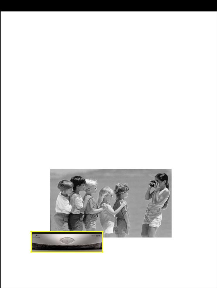
What makes HD digital signals (including SD signals) special is that they provide a high resolution and wide format, like a movie (16:9 TV aspect ratio). On the other hand, analog signals have the standard or normal format (4:3 TV aspect ratio). Thus, you receive programs with two distinct formats. Like a wide movie screen, the HD digital signals are formatted more like the way we actually see; our field of vision is more rectangular than square. So, when we view movies in a wide screen format, the image fills more of our field of vision yielding a stronger visual impact.
HD digital program signals use smaller pixels that are closer together. In the area taken up by a single pixel of a standard NTSC signal, HD digital signals will have four and a half pixels, four times the detail. The more pixels in a given area, the better the picture.
Some NTSC televisions can display a picture 720 pixels wide by 480 pixels high, that's a total of 345,600 pixels. HD digital signals can have a resolution of 1920 x 1080, that's 2,073,600 pixels, or six times more pixels than the older resolution. Pictures will be crisper and cleaner, with more detail in every close-up and every panorama.
206-3675
11
2. IMPORTANT OVERVIEW
2-3. Normal and Wide Format Signals
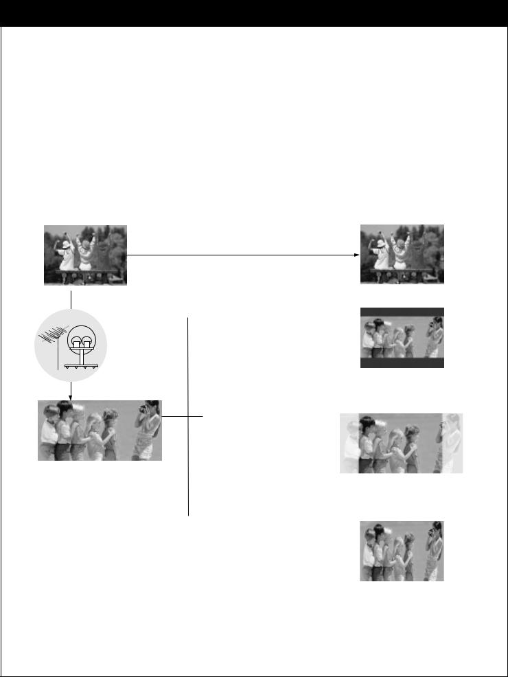
When you view a picture with a wide (16:9) aspect ratio with 480i or 480p mode of display format switch in the rear panel, the button changes the screen format in the cycle of Letterbox, Cropped, to Squeezed. When you view a picture with a normal (4:3) aspect ratio on a with 720p or 1080i mode of display format switch, the button changes the screen format in the cycle of Normal, Wide, Panorama, Zoom1, to Zoom2.
WHEN YOU SET THE DISPLAY FORMAT SWITCH TO SDTV (480I/480P)
Program Format |
|
Output Format |
No Adjustment Required
 Normal Picture (4:3)
 Letter box
Choose when you want to view a wide format (16:9) picture on a normal screen without squeezing.
antenna
 Cropped
Choose when you want to view a picture filling the entire screen while keeping the wide format.
Wide Picture (16:9) Left and right portions of the picture will not be shown.
 Squeezed
Choose when you want to view a full picture filling the entire screen with no black bars. The picture in a 16:9 format will be horizontally adjusted or squeezed to fit the 4:3 ratio monitor.
12
206-3675

2-3. Normal and Wide Format Signals
WHEN YOU SET THE DISAPLY SWITCH TO HDTV (1080I/720P)
No Adjustment Required
Wide Picture (16:9) |
Output Format (16:9) |
|
|
antenna
Adjustment
Required
Normal Picture (4:3)
Normal
Choose when you want to view a picture with an original 4:3 aspect ratio on your 16:9 TV. Black bars will show at the left and right sides.
 Wide
Wide
Choose when you want evenly stretch the width of a normal picture to fill a wide screen to fill the entire screen. You may find this setting useful for viewing 4:3 formatted DVD pictures.
 Panorama
Choose when you want stretch the edges of a normal picture to fill a wide screen.
 Zoom1
Zoom1
Choose when you want to fill the entire screen with the picture. The image will be altered both horizontally (stretched) and vertically (cropped). The top and bottom portions of the picture will not be shown. Zoom1 shows you the picture with a tradeoff between distortion and screen coverage.
 Zoom2
Zoom2
Choose when you want to view the picture without distortion. Some of the top and bottom portions of the picture will be deleted.
206-3675
13
2. IMPORTANT OVERVIEW
2-4. Audio Signals
Digital Audio Signals
left |
right |
speaker |
speaker |
|
sub-woofer |
surround |
surround |
sound |
sound |
speaker |
speaker |
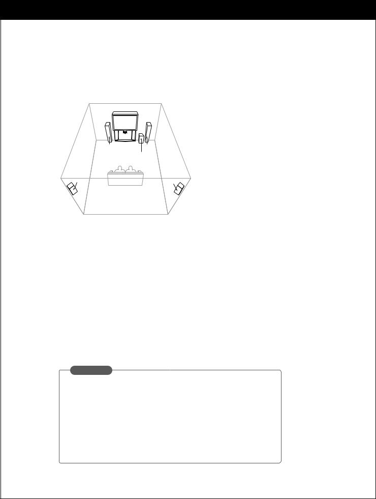
Dolby Digital Sound with 5.1 Channels
The Zenith HD Satellite Receiver will be the focal center of your home entertainment system comprising a variety of components, such as TV, DVD, VCR, etc. and external audio systems. Since digital programs being broadcast contain digital-quality audio, you can create a home theater by sending audio signals from the HD satellite receiver to your audio system externally. HD digital signals use the Dolby Digital audio encoding system - the same digital sound used in most movie theaters, on DVDs, and in many home theater systems.
When you tune to a channel, the Zenith HD Satellite Receiver can send signals either to a Dolby Digital decoder/receiver or to a PCM (normal digital) decoder. (* Refer to Section 3.7 Connection for Audio for making the required external connections to your system.)
Using the analog mode of the Zenith HD Satellite Receiver allows use of your Hi-Fi audio system instead of the TV speakers. This usually results in substantially improved sound.
GLOSSARY
known as AC-3 for Audio Coding 3rd Generation or is a coding technique that provides five independent, audio channels (three in left, center, and right, two right, and one low frequency effect for a sound you can
(PCM) decoders support L/R stereo only. If selectare decoded and transmitted in PCM mode.
14
206-3675

2-4. Audio Signals
Analog Audio Signals
Analog stereo amplifier
A/V |
A/V |
OUT2 |
OUT1 |
|
PB |
|
PR |
Audio cables
The analog audio outputs may be used to drive an external audio system. These stereo outputs are activated by setting the Analog mode in the Audio menu to Stereo.
If you set the Analog Mode to SAP (Second Audio Program), you can hear the program’s dialog in another language such as French or Spanish, if provided on the broadcast.
206-3675
15
2. IMPORTANT OVERVIEW
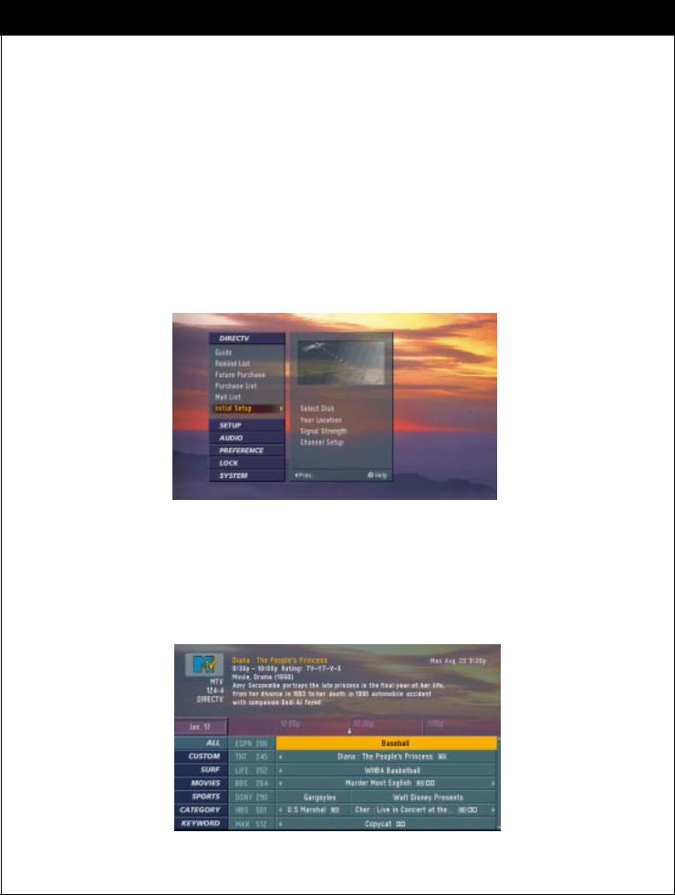
2-5. On-Screen Display
Main Menu
You can adjust the setup through a user-friendly on-screen menu using the remote control. While viewing a program, the on-screen menu will appear on your TV screen if you press the
Menu button on your remote control. The on-screen menu is operated using a simple, straight-forward ‘Highlight and Select’ process. You just highlight a menu item by using “DEFG” on the thumbstick of your remote control, and select it by pressing  . The onscreen menu also offers visual cues for easy guidance.
Advanced Program Guide
The Advanced Program Guide is an on-screen listing of current and future programs that are available from DIRECTV. The Zenith HD Satellite Receiver offers you a comprehensive program list that contains about programs with hundreds of channels, including analog Antenna and digital (ATSC). If you do not subscribe to DIRECTV programming, you will not be able to see the APG.
16
206-3675
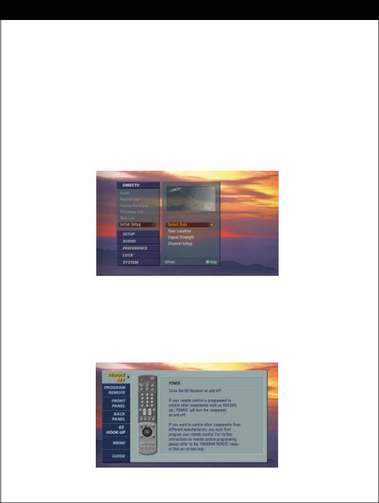
2-5. On-Screen Display
EZ Help
First, certain features and terminology used in the on-screen menus require your basic understanding to fully utilize their capabilities. The Zenith HD Satellite Receiver provides a powerful feature called “EZ Help” that describes highlighted menu item to help you understand the features. Press and hold the “Help (?)” button to display the “EZ Help”. Once you release the button, it disappears from the screen.
Second, if you press the “Help (?)” button while you are viewing a program with no menus on -screen, the Zenith HD Satellite Receiver provides a comprehensive on-screen user’s guide. It describes how to use your receiver.
This is, in fact, an on-line version of this Operating Guide.
206-3675
17

3. SETUP AND CONNECTIONS
3-1. |
Unpacking |
|
|
|
|
|
|||
|
Make sure you have received all these items listed below with the Zenith HD Satellite |
||||||||
|
Receiver. |
|
|
|
|
|
|
|
|
|
|
|
|
|
|
|
|
|
DOLBY |
|
|
|
|
|
|
|
|
|
D I G I T A L |
|
|
|
|
|
|
MENU |
|
|
|
|
|
|
|
|
|
|
|
ENTER |
|
|
|
|
|
|
|
GUIDE |
|
EXIT |
|
|
|
|
|
|
|
|
|
|
POWER |
|
Remote Control |
Cables (6 items) |
Batteries |
||||||
|
|
|
|
|
POWER |
|
|
|
AA |
|
|
|
MODE |
|
|
|
|
AA |
|
|
DIRECTV |
VCR |
AUX |
s-Video Jack |
|
|
|||
|
|
|
|
|
|||||
|
TV |
|
DVD |
|
|
|
|
|
|
|
1 |
|
|
2 |
3 |
Audio/Video Jacks |
|
||
|
|
|
|
|
|
|
|||
|
4 |
|
|
5 |
6 |
|
|
|
|
|
7 |
|
|
8 |
9 |
|
|
|
|
|
|
|
|
0 |
ENTER |
|
|
|
|
|
|
|
|
|
|
|
|
|
|
|
|
|
|
|
|
RF Jack |
|
|
|
|
MUTE |
|
|
|
RATIO |
|
|
|
|
|
|
|
|
Pg Up |
|
|
|
|
|
|
|
VOL |
Pg Dn |
|
|
|
|
|
|
|
|
CH |
|
|
|
|
|
||
|
|
|
|
|
|
|
|
|
|
|
SIGNAL |
FREEZE |
FLASHBK CC/DATE |
|
|
|
|
||
|
|
|
|
|
|
Digital Audio |
|
|
|
|
|
|
|
|
|
Out Jack |
|
|
|
|
MENU |
|
GUIDE |
SURF |
INFO |
|
|
|
|
|
|
|
|
|
|
|
|
||
|
HELP |
|
|
|
EXIT |
Phone Jacks |
|
|
|
|
|
|
|
|
|
|
|
|
|
|
RECORD |
|
STOP |
L CHAP |
R CHAP |
|
|
|
|
|
PAUSE |
|
REW |
PLAY |
FF |
|
|
|
|
|
|
|
|
|
|
Y |
PB |
PR |
|
18 |
|
|
|
|
|
|
|
|
-3675 |
|
|
|
|
|
|
|
|
206 |
|
|
|
|
|
|
|
|
|
|
|

3-1. Unpacking
HD satellite receiver
The Zenith HD Satellite Receiver is capable of receiving signals from the satellite dish, cable, and/or over- the-air antenna and sending the decoder signals into your TV.
Remote Control
In addition to the Zenith HD Satellite Receiver, the remote control can be programmed to control many other Zenith and non-Zenith devices.
Batteries
To install the batteries, slide open the battery compartment and insert the two AA batteries provided.
S-Video Jack and Cable
An S-Video jack is provided on the HD satellite receiver and is used together with audio cables. Remember to connect the left and right audio cables. An S-Video jack carries only the picture signals, not the sound.
Audio/Video Jacks and Cables
The Audio/Video jacks provide excellent picture and sound quality. They are used for making most Audio/Video connections between components. The Audio/Video jacks may be color coded (yellow for video, red for right audio, and white for left audio). If your component has only one input for audio (mono), connect it to the left (white L/mono) audio jack on the HD satellite receiver.
RF (Radio Frequency) Jacks and Coaxial Cables (F-type)
RF jacks are necessary for reception of over-the-air broadcasts, cable, and DIRECTV signals. These jacks are also required for antenna or cable connections. The RF and coaxial jacks on the HD satellite receiver are labeled Antenna, Cable, Satellite and OUT TO TV. An RG-6 type coaxial cable is required for satellite signal distribution.
Digital Audio Out Jacks and Cables
The optical cable and coaxial cable are used for connecting a Dolby Digital receiver. If you own a Dolby Digital receiver that uses an optical cable input, use an optical cable to connect the HD satellite receiver to that receiver.
Telephone Jack and Cord
The telephone line cord is required to connect your HD satellite receiver to a phone line. If you choose to subscribe to DIRECTV programming, this phone line is required to be connected.
Component Out Jacks and Cables
Component Cables are used to connect your HD satellite receiver to an industry standard Y PB PR compatible HD Monitor. A VGA cable can be also used to connect the HD satellite receiver to an industry-stan- dard RGB-compatible monitor Via the HD Monitor Out jack (not included in this package).
206-3675
19
3. SETUP AND CONNECTIONS
3-2. Back Panel of the Zenith HD Satellite Receiver |
||
Zenith HD Satellite Receiver Model DTV1080 Rear Panel |
||
A/V |
A/V |
|
OUT2 |
OUT1 |
|
|
CALIB/EZ-LINK |
|
|
DISPLAY |
|
|
FORMAT |
|
|
PB |
|
|
PR |
|
20 |
-3675 |
|
206 |
||
|
||

3-2. Back Panel of the Zenith HD Satellite Receiver
Ant In
Is used to connect an over-the-air or terrestrial antenna, your cable TV outlet, or cable box.
Cable In
Is used to connect a coaxial cable coming from your cable TV service outlet or cable box.
Out to TV
Provides an RF connection between the Zenith HD Satellite Receiver and the TV. Decoded signals are provided on channel 3 or 4 as selected in the menu. If the Zenith HD Satellite Receiver is in the standby mode, Cable or Antenna signals are provided as chosen in the Out to TV section of the Preference menu.
A/V Out 1,2
Is used to provide baseband audio and video signals to VCR or TV set. A/V connections generally provide picture quality that is superior to RF connections. For the highest quality picture connection, use the S-Video jack if it is available.
Component Out
Is used to connect to either a Y/PB/PR-compatible or RGB-compatible HD monitor. Either three video and two audio jacks for a Y/PB/PR monitor or a RGB jack for a RGB monitor need to be connected and the selector must be set accordingly.
Display Format
Sets the output resolution to one of 1080i, 720p, 480p and 480i formats. Choose the correct display format for your TV.
Digital Audio Out
Is used to connect either a digital optical cable or a coaxial cable from the HD satellite receiver to the Dolby Digital receiver or decoder. Dolby Digital enables the viewer to experience theater-quality sound using 5.1 audio channels.
EZ Link
Is the connection for the Zenith EZ Link.
Access Card
The access card is the means by which DIRECTV controls the distribution of its services. The card must be inserted into the access card slot (on the rear panel of the receiver) at all times to enable operation of the Zenith HD Satellite Receiver.
Phone Jack
Is used to receive certain premium services.
Satellite In
Is used to connect a satellite dish antenna to your receiver.
206-3675
21
3. SETUP AND CONNECTIONS
3-3. General Recommendations
CAUTION: Make all connections before plugging the power supply cord into a standard 120V, 60Hz AC power outlet.
You can connect the HD satellite receiver in a variety of configurations. The answers to the following questions will determine the correct setup for you.
-What type of antennas do you have? Satellite dish, cable, and/or over-the-air antennas.
-What type of connectors does your TV or VCR have: S-VIDEO, A/V (RCA_type), or RF coaxial?
-Do you want to use your HD satellite receiver with your audio or video systems?
-Do you have an audio or audio/video system? Consider integrating the HD satellite receiver into a home theater configuration to take advantage of the audio capabilities of your Dolby Digital System (Digital) or Hi-Fi System (Analog).
-Does your TV have an S-VIDEO jack? Use it to connect your TV to the HD satellite receiver. An S-VIDEO connection provides a better picture than RCA_type video or RF connections.
-Does your TV have RCA type A/V connectors, but no S-video jack? Use your TV’s A/V connectors
to connect your components. An A/V connection provides better picture and audio when compared to an RF connection.
Although there are numerous connections possible for optimum video and audio performance, try to follow the guidelines listed below when you hook up your components. Detailed hook-up instructions are provided on the following pages.
Connection |
Component |
Page |
To Antennas |
No Dish |
23 |
|
Round Dish (Satellite A) |
24 |
|
Oval Dish (Satellite A, B) |
25 |
|
Oval Dish (Satellite A, B, C) |
26 |
|
|
|
To TV |
Analog TV |
27 |
|
HD Monitor (Y/PB/PR type) |
28 |
|
HD Monitor (RGB type) |
29 |
|
|
|
To A/V Systems |
VCR |
30 |
|
Digital Audio System |
31 |
|
Analog Hi-Fi System |
32 |
|
|
|
Protect your components from power surges by turning off the component and unplugging power cords when you make connections.
Protect your component from overheating by keeping the ventilation holes open and not stacking components.
22
206-3675
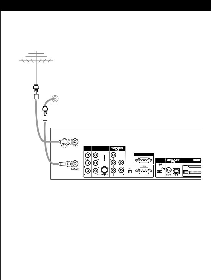
3-4. Connecting to Antennas - No Dish
Antenna |
Cable TV wall jack
A/V |
A/V |
OUT2 |
OUT1 |
|
CALIB/EZ-LINK |
|
DISPLAY |
|
FORMAT |
|
PB |
|
PR |
Receiving Signals
1.Connect the “Antenna” to the “ANT IN” jack on the HD Satellite Receiver using a coaxial RF cable.
2.Connect the cable TV signal to the “CABLE IN” jack of the HD Satellite Receiver using
a coaxial RF cable.
206-3675
23
3. SETUP AND CONNECTIONS
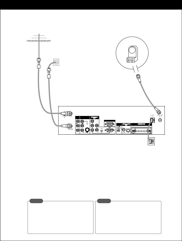
3-4. Connecting to Antennas - Round Dish (Satellite A)
Antenna |
|
|
Cable TV |
LNB |
|
Sat A |
||
wall jack |
||
|
Dish
1
A/V |
A/V |
OUT2 |
OUT1 |
|
CALIB/EZ-LINK |
|
DISPLAY |
|
FORMAT |
|
PB |
|
PR |
Phone wall jack
Receiving Signals
1.Connect the “Antenna” to the “ANT IN” jack on the HD Satellite Receiver using a coaxial RF cable.
2.Connect the cable TV signal to the "CABLE IN" jack on the Zenith HD Satellite Receiver using a coaxial RF cable.
3.Connect the “Jack 1” of the dish antenna to the “SATELLITE IN” jack on the HD Satellite Receiver using a coaxial RF cable. (For proper dish installation, refer to the “Installer’s Guide” provided with your satel lite dish antenna.)
4.Connect the “Phone Wall Jack” to “PHONE JACK” on the HD Satellite Receiver using a phone cable.
NOTE |
NOTE |
While you are subscribing to a DIRECTV programming package, you can still view over-the- air and cable TV programs, if you make connections to the over-the-air and/or cable jacks.
You will not be able to receive DIRECTV HD
programming with a Round dish.
24
206-3675
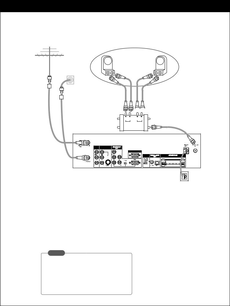
3-4. Connecting to Antennas - Oval Dish (Satellite A, B)
Antenna |
Cable TV |
wall jack |
LNB |
LNB |
Sat A |
Sat B |
Dish

 Multi switch
|
4 |
2 |
|
18V 13V |
18V 13V |
|
Sat A ln |
Sat B ln |
|
3 |
1 |
A/V |
A/V |
|
OUT2 |
OUT1 |
|
|
CALIB/EZ-LINK |
|
|
|
DISPLAY |
|
|
FORMAT |
|
PB |
|
|
PR |
|
Phone wall jack
Receiving Signals
1.Connect the “Antenna” to the “ANT IN” jack on the HD Satellite Receiver using a coaxial RF cable.
2.Connect the cable TV signal to the "CABLE IN" jack on the HD Satellite Receiver using a coaxial RF cable.
3.Connect the “Jack 1” of the multi-switch to the “SATELLITE IN” jack on the HD satellite receiver using a coaxial RF cable. (For proper dish installation, refer to the “Installer’s Guide” provided with your satellite dish antenna.)
4.Connect the “Phone Wall Jack” to “PHONE JACK” on the HD satellite receiver using a phone cable.
NOTE
While you are subscribing to a DIRECTV programming package, you can still view over-the- air and cable TV programs, if you make connections to the over-the-air and/or cable jacks.
206-3675
25
3. SETUP AND CONNECTIONS
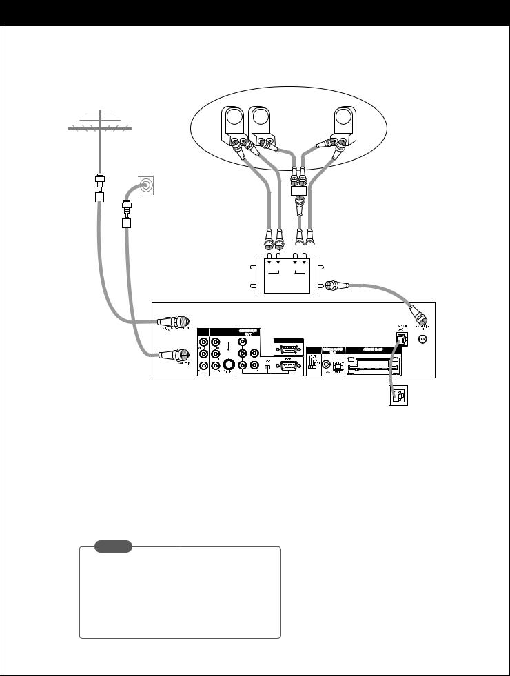
3-4. Connecting to Antennas - Oval Dish (Satellite A, B, C)
Antenna |
Cable TV |
wall jack |
LNB |
LNB |
LNB |
Sat A |
Sat C |
Sat B |
Dish

 Multi switch
|
4 |
2 |
|
18V 13V |
18V 13V |
|
Sat A ln |
Sat B ln |
|
3 |
1 |
A/V |
A/V |
|
OUT2 |
OUT1 |
|
|
CALIB/EZ-LINK |
|
|
|
DISPLAY |
|
|
FORMAT |
|
PB |
|
|
PR |
|
Phone wall jack
Receiving Signals
1.Connect the “Antenna” to the “ANT IN” jack on the HD Satellite Receiver using a coaxial RF cable.
2.Connect the cable TV signal to the "CABLE IN" jack on the HD Satellite Receiver using a coaxial RF cable.
3.Connect the “Jack 1” of the multi-switch to the “SATELLITE IN” jack on the HD Satellite Receiver using a coaxial RF cable. (For proper dish installation, refer to the “Installer’s Guide” provided with your satellite dish antenna.)
4.Connect the “Phone Wall Jack” to “PHONE JACK” on the HD Satellite Receiver using a phone cable.
NOTE
While you are subscribing to a DIRECTV programming package, you can still view over-the-air and cable TV programs, if you make connections to the over-the-air and/or cable jacks.
26
206-3675

3-5. TV Connection - Analog TV
Antenna
Cable TV wall jack
|
Analog TV |
IN |
V L R |
Multi-switch
A/V |
A/V |
OUT2 |
|
CALIB/EZ-LINK
DISPLAY
FORMAT
PB
PR
Phone wall jack
TV Viewing
1.Connect the “OUT TO TV” jack on the HD satellite receiver to the “ANT IN” jack on your TV using a coaxial RF cable.
2.Connect the “A/V OUT” jack on the HD satellite receiver to the “A/V IN” jack on your TV using RCA_type cables.
206-3675
27
3. SETUP AND CONNECTIONS
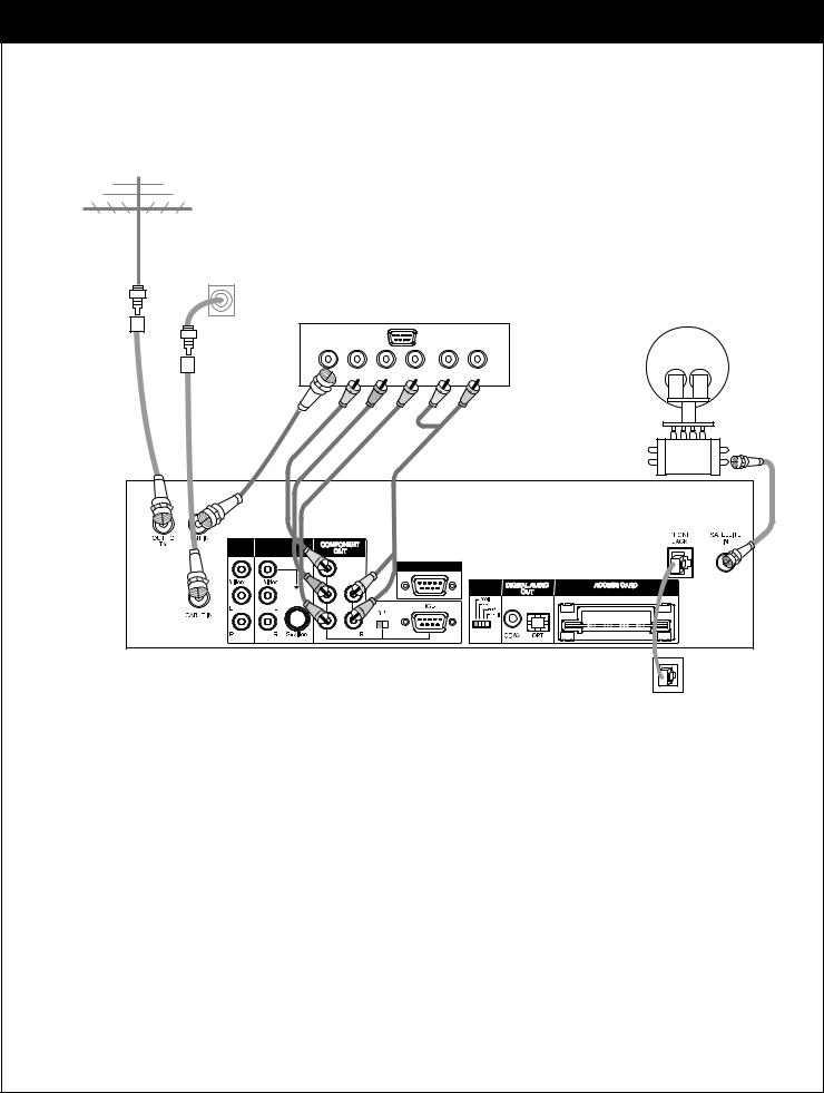
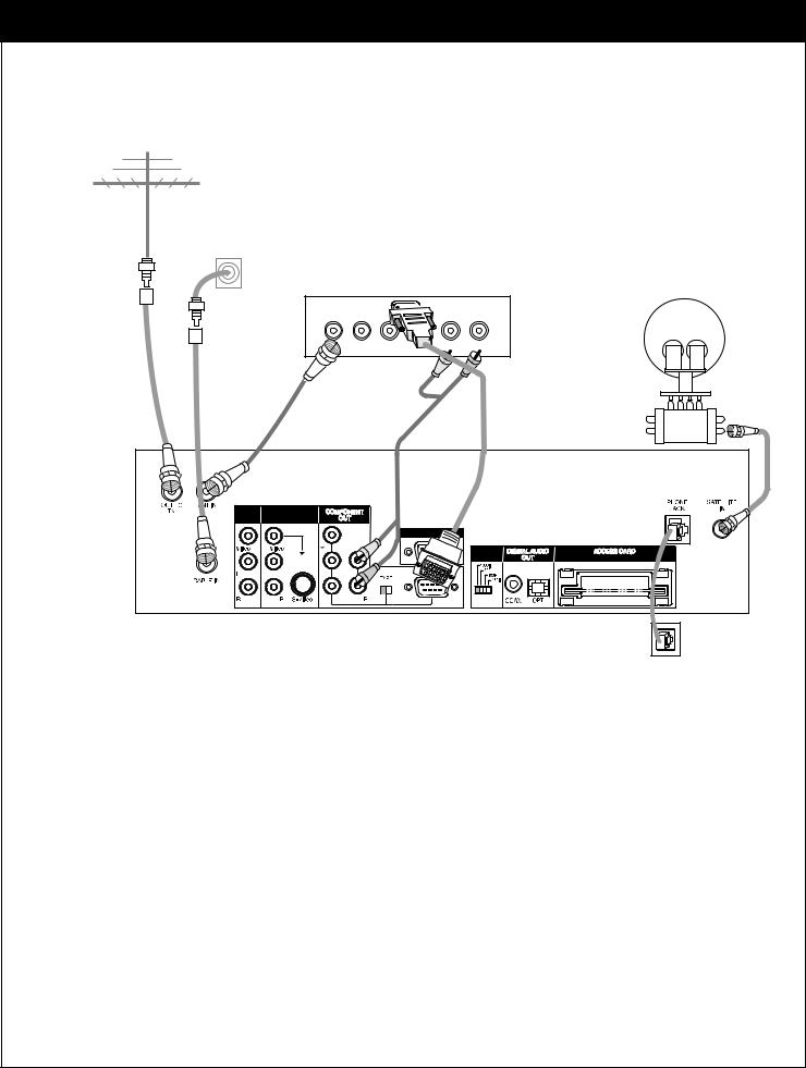
3-5. TV Connection - HD Monitor (Y/PB/PR type)
Antenna |
Cable TV |
wall jack |
HD-Ready TV
Y Pb Pr |
L |
R |
Multi-switch
A/V |
A/V |
OUT2 |
OUT1 |
|
CALIB/EZ-LINK |
|
DISPLAY |
|
FORMAT |
|
PR |
Phone wall jack
TV Viewing
1.Connect the “OUT TO TV” jack on the HD Satellite Receiver to the “ANT IN” jack on your TV using a coaxial RF cable.
2.Connect the "COMPONENT OUT" jacks on the HD Satellite Receiver to the "COMPONENT IN" jacks of your
TV using RCA_type cables. (The "TYPE" switch must be set toward the "Y/PB/PR" jacks.)
3. Connect the L/R "COMPONENT OUT" jacks on the HD Satellite Receiver to the L/R "COMPONENT IN" jacks on your TV using RCA_type connectors.
28
206-3675
3-5. TV Connection - HD Monitor (RGB type)
Antenna |
Cable TV |
wall jack |
HD-Ready TV
Y Pb |
L |
R |
Multi-switch
A/V |
A/V |
OUT2 |
OUT1 |
|
CALIB/EZ |
|
DISPLAY |
|
FORMAT |
|
PB |
|
PR |
Phone wall jack
TV Viewing
1.Connect the “OUT TO TV” jack on the HD Satellite Receiver to the “ANT IN” jack on your TV using a coaxial RF cable.
2.Connect the "COMPONENT OUT" jacks on the HD Satellite Receiver to the "COMPONENT IN" jacks of your
TV using RCA_type cables. (The "TYPE" switch must be set toward the "RGB" jacks.)
3. Connect the L/R "COMPONENT OUT" jacks on the HD Satellite Receiver to the L/R "COMPONENT IN" jacks on your TV using RCA_type connectors.
206-3675
29
 Loading...