


Zenith H2546DT, H3246DT, H3646DT, IQB36C95W, H2547DT OPERATING GUIDE
...machine numbers |
|
H2546DT |
H3246DT |
|
H3646DT |
|
IQB36C95W |
||
|
|
|
|||||||
|
|
H2547DT |
|
H2747DT |
|
|
H3247DT |
|
H3647DT |
|
|
|
|
|
|
||||
|
|
|
|
|
|
||||
t a b l e o f c o n t e n t s |
5 |
p a g e |
h o o k u p d i r e c t o r y
c o m p u t e r h o o k u p |
12 |
p a g e |
y o u r o n - s c r e e n m e n u s |
19 |
p a g e |
g l o s s a r y
p a g e 46
i n s t a l l a t i o n & o p e r a t i n g g u i d e / w a r r a n t y
RECORD YOUR MODEL NUMBER
The model and serial number of your new TV are located on the back of the TV cabinet. For your future convenience, we suggest that you record these numbers here:
MODEL NO.____________________________________
SERIAL NO.____________________________________
WARNING
RISK OF ELECTRIC SHOCK
DO NOT OPEN
WARNING:
TO REDUCE THE RISK OF ELECTRIC SHOCK DO NOT REMOVE COVER (OR BACK). NO USER SERVICEABLE PARTS INSIDE. REFER TO QUALIFIED SERVICE PERSONNEL.
The lightning flash with arrowhead symbol, within an equilateral triangle, is intended to alert the user to the presence of uninsulated “dangerous voltage” within the product’s enclosure that may be of sufficient magnitude to constitute a risk of electric shock to persons.
The exclamation point within an equilateral triangle is intended to alert the user to the presence of important operating and maintenance (servicing) instructions in the literature accompanying the appliance.
WARNING:
TO PREVENT FIRE OR SHOCK HAZARDS, DO NOT EXPOSE THIS PRODUCT TO RAIN OR MOISTURE.
POWER CORD POLARIZATION:
This product is equipped with a 3-wire grounding-type alternating current line plug. This plug will fit into the power outlet only one way. This is a safety feature. If you are unable toinsert the plug fully into the outlet, contact your electrian to replace your obsolete outlet. Do not defeat the safety purpose of the three-wire ground type plug.
NOTE TO CABLE/TV INSTALLER:
This reminder is provided to call the cable TV system installer’s attention to Article 820-40 of the National Electric Code (U.S.A.). The code provides guidelines for proper grounding and, in particular, specifies that the cable ground shall be connected to the grounding system of the building, as close to the point of the cable entry as practical.
REGULATORY INFORMATION:
This equipment has been tested and found to comply with the limits for a Class B digital device, pursuant to Part 15 of the FCC Rules. These limits are designed to provide reasonable protection against harmful interference when the equipment is operated in a residential installation. This equipment generates, uses and can radiate radio frequency
energy and, if not installed and used in accordance with the instruction manual, may cause harmful interference to radio communications. However, there is no guarantee that interference will not occur in a particular installation. If this equipment does cause harmful interference to radio or television reception, which can be determined by turning
the equipment off and on, the user is encouraged to try to correct the interference by one or more of the following measures: • Reorient or relocate the receiving antenna.
•Increase the separation between the equipment and receiver.
•Connect the equipment into an outlet on a circuit different from that to which the receiver is connected.
•Consult the dealer or an experienced radio/TV technician for help.
CAUTION:
Do not attempt to modify this product in any way without written authorization from Zenith Electronics Corporation. Unauthorized modification could void the user’s authority to operate this product.
COMM-WARN B-3/99

IMPORTANT SAFETY INSTRUCTIONS
Important safeguards for you and your new product
Your product has been manufactured and tested with your safety in mind. However, improper use can result in potential electrical shock or fire hazards. To avoid defeating the safeguards that have been built into your new product, please read and observe the following safety points when installing and using your new product, and save them for future reference.
Observing the simple precautions discussed in this booklet can help you get many years of enjoyment and safe operation that are built into your new product.
This product complies with all applicable U.S. Federal safety requirements, and those of the Canadian Standards Association.
1. Read Instructions
All the safety and operating instructions should be read before the product is operated.
2. Follow Instructions
All operating and use instructions should be followed.
3. Retain Instructions
The safety and operating instructions should be retained for future reference.
4. Heed Warnings
All warnings on the product and in the operating instructions should be adhered to.
5. Cleaning
Unplug this product from the wall outlet before cleaning. Do not use liquid cleaners or aerosol cleaners. Use a damp cloth for cleaning.
6. Water and Moisture
Do not use this product near water for example, near a bath tub, wash bowl, kitchen sink, or laundry tub, in a wet basement, or near a swimming pool.
7. Accessories
Do not place this product on an unstable cart, stand, tripod, bracket, or table. The product may fall, causing serious injury to a child or adult, and serious damage to the product. Use only with a cart, stand, tripod, bracket, or table recommended by the manufacturer, or sold with the product. Any mounting of the product should follow the manufacturer’s instructions, and should use a mounting accessory recommended by the manufacturer.
8. Transporting Product
A product and cart combination should be moved with care. Quick stops, excessive force, and uneven surfaces may cause the product and cart combination to overturn.
9. Attachments
Do not use attachments not recommended by the product manufacturer as they may cause hazards.
10. Ventilation
Slots and openings in the cabinet are provided for ventilation and to ensure reliable operation of the product and to protect it from overheating, and these openings must not be blocked or covered. The openings should never be blocked by placing the product on a bed, sofa, rug, or other similar surface. This product should not be placed in a built-in installation such as a bookcase or rack unless proper ventilation is provided or the manufacturer’s instructions have been adhered to.
11. Power Sources
This product should be operated only from the type of power source indicated on the marking label. If you are not sure of the type of power supply to your home, consult your product dealer or local power company. For products intended to operate from battery power, or other sources, refer to the operating instructions.
12. Line-Cord Polarization
This product is equipped with a 3-wire grounding type alternating-current line plug. This plug will fit into the power outlet only one way. This is a safety feature. If you are unable to insert the plug fully into the outlet, contact your electrician to replace your obsolete outlet. Do not defeat the safety purpose of the three-wire ground-type plug.
13. Power-Cord Protection
Power-supply cords should be routed so that they are not likely to be walked on or pinched by items placed upon or against them, paying particular attention to cords at plugs, convenience receptacles, and the point where they exit from the product.
(Continued on next page)
PORTABLE CART WARNING
206-3489-O 3-WIRE GRND |
P A G E 3 |
IMPORTANT SAFETY INSTRUCTIONS
(Continued from previous page)
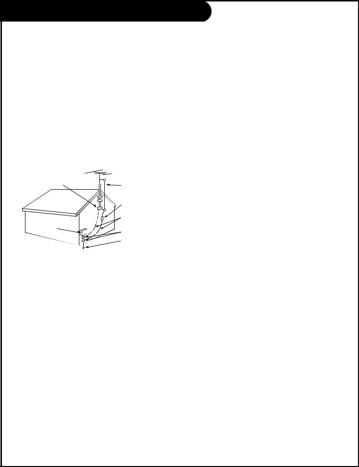
14. Outdoor Antenna Grounding
If an outside antenna or cable system is connected to the product, be sure the antenna or cable system is grounded so as to provide some protection against voltage surges and built-up static charges. Article 810 of the National Electrical Code (U.S.A.), ANSI/ NFPA 70 provides information with regard to proper grounding of the mast and supporting structure, grounding of the lead-in wire to an antenna discharge unit, size of grounding conductors, location of antenna-discharge unit, connection to grounding electrodes, and requirements for the grounding electrode.
Example of Grounding According to National Electrical Code Instructions
Ground Clamp
|
|
Antenna Lead in Wire |
|
|
|
|
|
Antenna Discharge Unit |
|
|
(NEC Section 810-20) |
|
|
Grounding Conductor |
Electric Service |
|
(NEC Section 810-21) |
|
|
|
Equipment |
|
Ground Clamps |
|
|
|
|
|
Power Service Grounding |
|
|
Electrode System (NEC |
|
|
Art 250, Part H) |
NEC - National Electrical Code
18. Object and Liquid Entry
Never push objects of any kind into this product through openings as they may touch dangerous voltage points or short-out parts that could result in a fire or electric shock. Never spill liquid of any kind on the product.
19. Servicing
Do not attempt to service this product yourself as opening or removing covers may expose you to dangerous voltage or other hazards. Refer all servicing to qualified service personnel.
20. Damage Requiring Service
Unplug this product from the wall outlet and refer servicing to qualified service personnel under the following conditions:
a.If the power-supply cord or plug is damaged.
b.If liquid has been spilled, or objects have fallen into the product.
c.If the product has been exposed to rain or water.
d.If the product does not operate normally by following the operating instructions. Adjust only those controls that are covered by the operating instructions as an improper adjustment of other controls may result in damage and will often require extensive work by a qualified technician to restore the product to its normal operation.
e.If the product has been dropped or the cabinet has been damaged.
f.If the product exhibits a distinct change in performance.
15. Lightning
For added protection for this product (receiver) during a lightning storm, or when it is left unattended and unused for long periods of time, unplug it from the wall outlet and disconnect the antenna or cable system. This will prevent damage to the product due to lightning and power-line surges.
16. Power Lines
An outside antenna system should not be located in the vicinity of overhead power lines or other electric light or power circuits, or where it can fall into such power lines or circuits. When installing an outside antenna system, extreme care should be taken to keep from touching such power lines or circuits as contact with them might be fatal.
21. Replacement Parts
When replacement parts are required, be sure the service technician has used replacement parts specified by the manufacturer or have the same characteristics as the original part. Unauthorized substitutions may result in fire, electric shock, or other hazards.
22. Safety Check
Upon completion of any service or repairs to this product, ask the service technician to perform safety checks to determine that the product is in proper operating condition.
23. Wall or Ceiling Mounting
The product should be mounted to a wall or ceiling only as recommended by the manufacturer.
17. Overloading
Do not overload wall outlets and extension cords as this can result in a risk of fire or electric shock.
24. Heat
The product should be situated away from heat sources such as radiators, heat registers, stoves, or other products (including amplifiers) that produce heat.
P A G E 4 |
206-3489-O |

Table of Contents
Turn to the next page to begin the TV setup
Safety Warnings . . . . . . . . . . . . . . . . . . . . . . . . . . . .2 Important Safety Information . . . . . . . . . . . . . . . . . . .3 Table of Contents . . . . . . . . . . . . . . . . . . . . . . . . . . .5
Step 1. Hook Up TV
TV/VCR/Cable Box/Computer and other Equipment Hookup Antenna . . . . . . . . . . . . . . . . . . . . . . . . . . . . . . . . .7 Cable service . . . . . . . . . . . . . . . . . . . . . . . . . . . . . .8 Antenna with VCR . . . . . . . . . . . . . . . . . . . . . . . . . . .9 Cable service with VCR . . . . . . . . . . . . . . . . . . . . . . .10 S-VHS VCR/External Amplifier . . . . . . . . . . . . . . . . . . .11 Computer . . . . . . . . . . . . . . . . . . . . . . . . . . . . . . . .12 Computer Mode Remote Control Key command Functions .14
Step 2. Reception Setup and Channel Search
Auto Program: Select Antenna, or Cable service
and do channel search . . . . . . . . . . . . . . . . . . . . . . .16 Front Panel Controls/Inputs . . . . . . . . . . . . . . . . . . . .17 Remote Control Key Functions in TV mode . . . . . . . . . .18 On-Screen Menus Overview . . . . . . . . . . . . . . . . . . . . 19
Step 3. Customize the Presentation TV’s
Features
Setup Menu (Start with page 16, Auto Program) Add/Del/Blank . . . . . . . . . . . . . . . . . . . . . . . . .20 Channel Labels . . . . . . . . . . . . . . . . . . . . . . . . .21 Clock Set . . . . . . . . . . . . . . . . . . . . . . . . . . . . .23 Alarm . . . . . . . . . . . . . . . . . . . . . . . . . . . . . . .24
Language . . . . . . . . . . . . . . . . . . . . . . . . . . . . .25 Audio Menu . . . . . . . . . . . . . . . . . . . . . . . . . . . . . .26 Video Menu . . . . . . . . . . . . . . . . . . . . . . . . . . . . . .27 Parental Control Menu . . . . . . . . . . . . . . . . . . . . . .28
Other Menus and On-Screen Displays
Source menu . . . . . . . . . . . . . . . . . . . . . . . . . . .30 Channel/Time/Audio Display . . . . . . . . . . . . . . . .30 Alarm menu . . . . . . . . . . . . . . . . . . . . . . . . . . .30 Sleep Timer menu . . . . . . . . . . . . . . . . . . . . . . .30 Volume Display . . . . . . . . . . . . . . . . . . . . . . . . .30 Closed Captions/Text menu . . . . . . . . . . . . . . . . .30 Ch Preview menu . . . . . . . . . . . . . . . . . . . . . . . .30
Installer Menus . . . . . . . . . . . . . . . . . . . . . . . . . . . .31 LT1500 Quickset Clone Programmer Operation . . . . . . . .34 Remote Control Programming . . . . . . . . . . . . . . . . . . .37 Amplifier Volume Override . . . . . . . . . . . . . . . . . .38 Aux 1, Aux 2, Aux 3 Programming . . . . . . . . . . . . .39 AutoFind . . . . . . . . . . . . . . . . . . . . . . . . . . . . .40 Programming Product Brand Codes . . . . . . . . . . . .41 Remote Modes Key Functions . . . . . . . . . . . . . . . .43 Maintenance . . . . . . . . . . . . . . . . . . . . . . . . . . . . . .44 Troubleshooting . . . . . . . . . . . . . . . . . . . . . . . . . . .45 Glossary . . . . . . . . . . . . . . . . . . . . . . . . . . . . . . . .46 Warranty for Presentation Series TVs . . . . . . . . . . . . . .48
Purchase the Optional Installer’s Remote and Clone Programmer
To preform the installation setup, you need an installer’s remote like the LP702, and the LT1500 Clone Programmer - - both are shown and described in later sections. The installer remote allows access to the Service menus, User menus, and Source/Channel Bank keys. The installer remote has Menu, Select, and Adjust Keys (Up/Down/Left/Right arrows) and Source/Channel Bank Keys. The LT1500 Clone Programmer is used to duplicate a TV’s setup and install it on another TV. See your Zenith Dealer.
206-3492-O |
PresentationTM TV is a trademark of Zenith Electronics Corporation |
P A G E 5 |
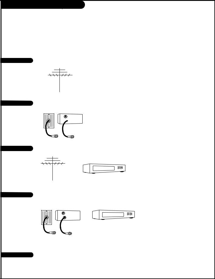
Basic Hook-Up Directory
To hook up a computer see pages 12-13. To hookup other equipment, see below.
IMPORTANT!!
Use this page to decide where you need to begin your set up. First, find the line below that best describes what you want to do, then go to that page number.
If you are using an antenna and no other equipment, go to . . . . . . . . . . . . . . . . . . page 7
If you have cable and no other equipment, go to . . . . . . . . . . . . . . . . . . . . . . . . . page 8
Cable TV wall jack
In |
Cable box |
Out 
Antenna with VCR |
If you are using an antenna and have a VCR, go to . . . . . . . . . . . . . . . . . . . . . . . |
page 9 |
Cable and VCR |
If you have cable and a VCR, go to . . . . . . . . . . . . . . . . . . . . . . . . . . . . . . . . . . |
page 10 |
|
|
Cable TV |
|
|
|
wall jack |
|
|
|
In |
Cable box |
|
|
Out |
|
|
If you want to connect an S-VHS VCR or External Amplifier with speakers . . . . . . . . . .page 11
206-3492-A
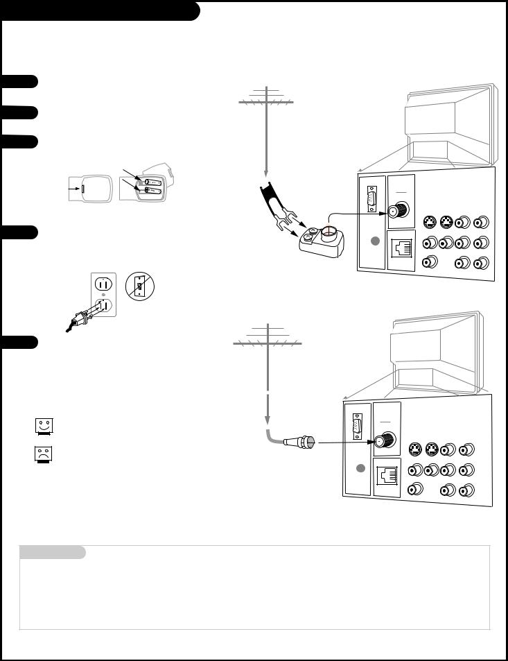
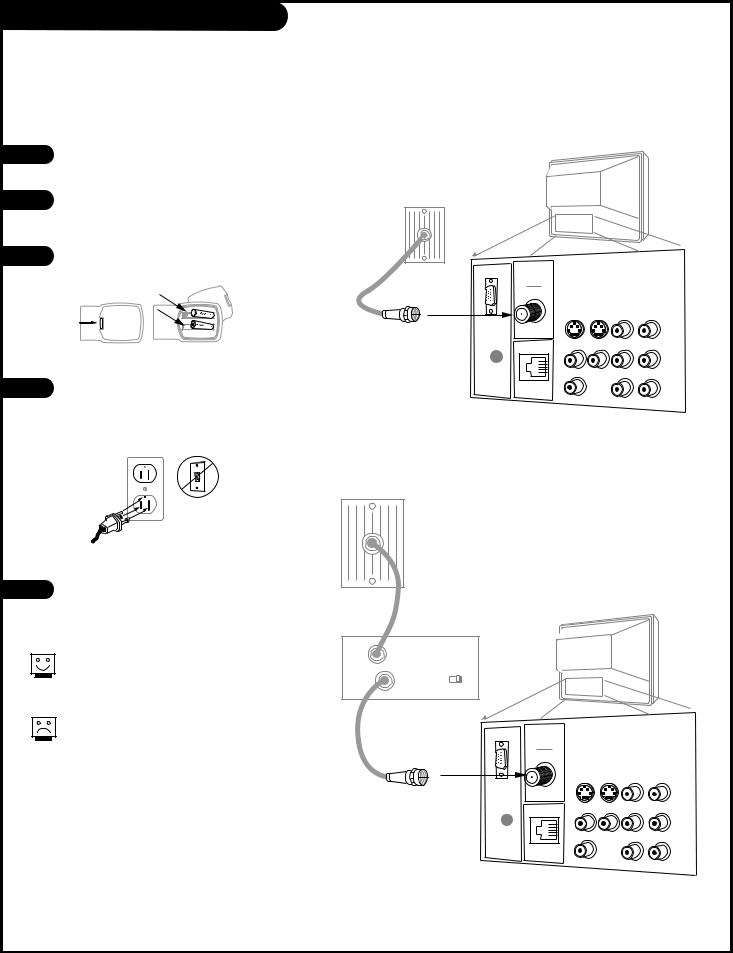
Hook Up Your Antenna to the TV
Connect an off-air antenna to the Presentation TV
1
2
3
Locate the Antenna/Cable jack on the back of your Presentation TV.
Connect the cable that runs from the wall directly to this jack, according to the diagram to the right.
Remove the back of the remote and put in two AAA batteries.
TV back
Antenna
back of remote
4 |
Plug in your TV. Do not plug it into a switched out- |
|
|
|
let. Your Entertainment Machine is designed to oper- |
|
ate on standard current, 120-volt 60 Hertz AC. Do |
|
not attempt to operate it on DC Current. |
Flat wire
(300 ohm)
ANTENNA
CABLE
300/75 ohm
Adapter |
S-VIDEO OUT |
S-VIDEO IN |
R- AUDIO- L |
|
COMPUTER |
|
|
|
IN |
|
|
|
M.P.I. |
VIDEO AUX IN |
R- AUDIO- L |
|
|
|
|
|
R |
|
|
|
AUDIO OUT |
|
R- AUDIO- L |
|
L |
COMPUTER |
|
|
AUDIO |
|
5 |
Go to page 16 to Auto Program your Presentation TV. |
TV back |
|
|
|
|
|
Antenna |
If you have a 75 ohm RF cable, then you don’t need any adapters!
A 300 to 75 ohm adapter is not included with the Zenith Presentation TV.
RF coaxial wire (75ohm)
ANTENNA
CABLE |
|
|
S-VIDEO OUT |
S-VIDEO IN |
R- AUDIO- L |
COMPUTER |
|
|
IN |
|
|
M.P.I. |
VIDEO AUX IN |
R- AUDIO- L |
|
|
|
R |
|
|
AUDIO OUT |
|
R- AUDIO- L |
L |
COMPUTER |
|
AUDIO |
|
Mini glossary
75 OHM RF CABLE
300 TO 75 OHM ADAPTER
The wire that comes from an off-air antenna or cable service provider. Each end looks like a hex shaped nut with a wire sticking through the middle, and it screws onto the threaded jack on the back of your TV.
A small device that connects a two-wire 300 ohm antenna to a 75 ohm RF jack. They are usually about an inch long with two screws on one end and a round opening with a wire sticking out on the other end.
206-3492-O |
P A G E 7 |
Hook Up Your Cable (CATV) to the TV
Connect cable service to the Presentation TV
1 |
Locate the Antenna/Cable jack on the back of |
|
the Presentation TV. |
||
|
||
2 |
Connect the cable that runs from the wall |
|
directly to this jack, according to the diagram |
||
|
to the right. |
|
3 |
Remove the back of the remote and put in two |
|
AAA batteries. |
||
|
||
|
back of |
|
|
remote |
|
4 |
Plug in the TV. Do not plug it into a switched |
|
outlet. Your Presentation TV is designed to |
||
|
||
|
operate on standard current, 120-volt 60 Hertz |
|
|
AC. Do not attempt to operate it on DC |
|
|
Current. |
Cable TV |
TV back |
|
wall jack |
||
|
ANTENNA
CABLE
Round wire (75ohm)
S-VIDEO OUT |
S-VIDEO IN |
R- AUDIO- L |
COMPUTER |
|
|
IN |
|
|
M.P.I. |
VIDEO AUX IN |
R- AUDIO- L |
|
|
|
R |
|
|
AUDIO OUT |
|
R- AUDIO- L |
L |
COMPUTER |
|
AUDIO |
|
Cable TV wall jack
5 |
Go to page 16 to Auto Program the |
|
|
|
Presentation TV. |
If you’re using a cable box, leave the TV on channel 3 or 4 and use your cable box to change channels.
If you’re using a cable box, Auto Program might only find the channel your cable service is on (usually channel 3 or 4). Don’t worry, that’s all you need!
In |
Cable box |
TV back |
|
Out |
output |
|
|
switch |
3 4 |
|
|
|
|
||
ANTENNA
RF coaxial wire (75ohm) |
CABLE |
S-VIDEO OUT |
S-VIDEO IN |
R- AUDIO- L |
COMPUTER |
|
|
IN |
|
|
M.P.I. |
VIDEO AUX IN |
R- AUDIO- L |
|
|
|
R |
|
|
AUDIO OUT |
|
R- AUDIO- L |
L |
COMPUTER |
|
AUDIO |
|
P A G E 8 |
206-3489-O |
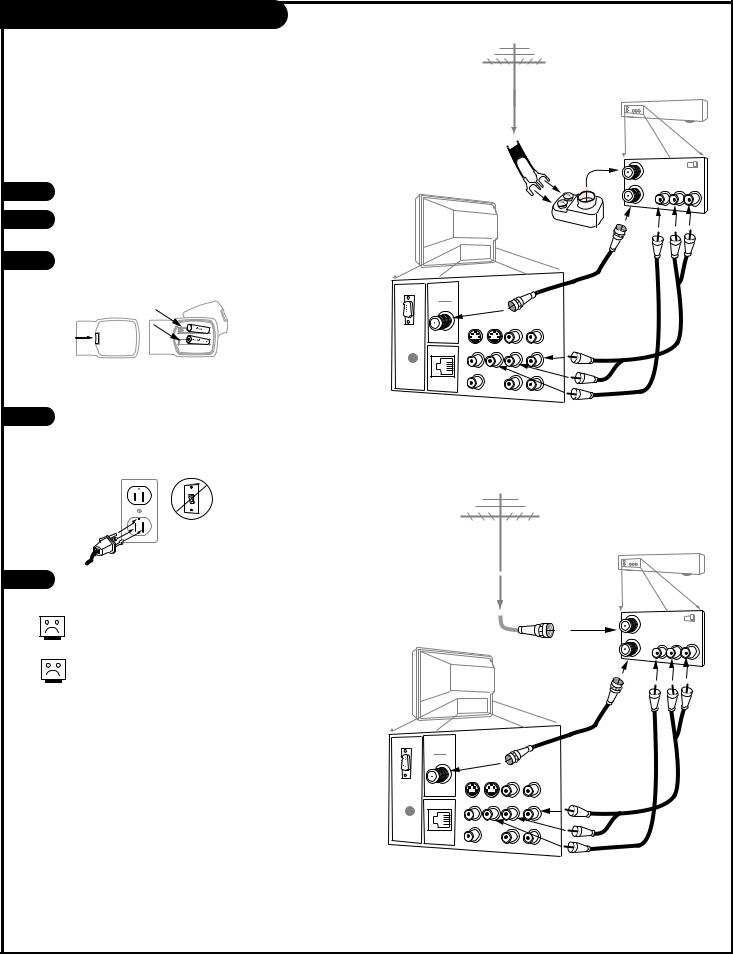
Hook Up Antenna and VCR to the TV
Connect your off-air antenna and VCR to the Presentation TV
1 |
Locate the Antenna/Cable jack on the back of the VCR. |
|
|
||
2 |
Connect the cable that runs from the antenna directly to |
|
this jack, according to the diagram to the right. |
||
|
||
3 |
Remove the back of the remote and put in two AAA bat- |
|
|
teries. |
Antenna |
Flat wire (300 ohm)
VCR back
VCR back AV panel
300/75 ohm |
In |
output |
3 4 |
Adapter |
|
switch |
|
|
Out |
Video Audio |
|
TV back
back of remote
ANTENNA
CABLE
A/V cables not included
S-VIDEO OUT |
S-VIDEO IN |
R- AUDIO- L |
with TV |
COMPUTER |
|
|
|
|
|
|
|
IN |
|
|
|
M.P.I. |
VIDEO AUX IN |
R- AUDIO- L |
|
|
|
|
|
R |
|
|
|
AUDIO OUT |
|
R- AUDIO- L |
|
L |
COMPUTER |
|
|
AUDIO |
|
|
4 Plug in the TV. Do not plug it into a switched outlet. The Presentation TV is designed to operate on standard current, 120-volt 60 Hertz AC. Do not attempt to operate it on DC Current.
5 |
Go to page 16 to Auto Program the Presentation TV. |
No A/V cables are included with the Zenith Presentation TV.
Without A/V cables, most VCRs will not play videocassettes in stereo sound.
Antenna |
|
|
|
|
|
VCR back |
|
RF coaxial wire |
VCR back AV panel |
|
|
|
|
|
|
(75ohm) |
In |
output |
4 |
|
|
switch 3 |
|
|
Out |
Video Audio |
|
TV back |
|
|
|
ANTENNA
CABLE
A/V cables not included
S-VIDEO OUT |
S-VIDEO IN |
R- AUDIO- L |
with TV |
COMPUTER |
|
|
|
|
|
|
|
IN |
|
|
|
M.P.I. |
VIDEO AUX IN |
R- AUDIO- L |
|
|
|
|
|
R |
|
|
|
AUDIO OUT |
|
R- AUDIO- L |
|
L |
COMPUTER |
|
|
AUDIO |
|
|
206-3492-O |
P A G E 9 |

Hook Up Cable Service (CATV) and VCR
Connect a VCR and Cable service to the Presentation TV.
Cable TV wall jack
|
VCR back |
VCR back AV panel |
|
Round wire (75ohm) |
output |
In |
|
|
switch 3 4 |
1 |
Locate the Antenna/Cable jack on the back of the |
|
VCR. |
||
|
||
2 |
Connect the cable that runs from the wall directly |
|
|
to this jack, according to the diagram to the |
|
|
right. |
|
3 |
Remove the back of the remote and put in two |
|
AAA batteries. |
||
|
||
|
back of |
|
|
remote |
|
4 |
Plug in the TV. Do not plug it into a switched |
outlet. The Presentation TV is designed to operate on standard current, 120-volt 60 Hertz AC. Do not attempt to operate it on DC Current.
5 |
Go to page 16 to Auto Program the Presentation |
|
TV. |
Leave the VCR and the television tuned to channel three and use the cable box to change channels.
No A/V cables are included with your Presentation TV. Without A/V cables, most VCRs will not play videocassettes in stereo sound.
Out Video Audio
TV back |
RF coaxial wire |
|
(75ohm) |
||
|
||
|
not included |
|
|
with TV |
|
|
A/V cables |
|
ANTENNA |
not included |
|
CABLE |
with TV |
|
|
||
S-VIDEO OUT |
S-VIDEO IN R- AUDIO- L |
|
COMPUTER |
|
|
IN |
|
|
M.P.I. |
VIDEO AUX IN R- AUDIO- L |
|
R |
|
|
AUDIO OUT |
R- AUDIO- L |
|
L |
COMPUTER |
|
AUDIO |
Cable TV wall jack
In |
Cable box |
|
VCR back |
||
|
|
||||
Out |
output |
|
|
|
|
switch 3 |
4 |
|
|
||
|
|
|
|||
RF coaxial wire (75ohm) |
VCR back AV panel |
||||
In |
output |
||||
|
|
|
|||
|
|
|
|
switch 3 4 |
|
|
|
|
Out |
Video Audio |
|
TV back |
|
|
|
|
|
|
|
|
RF coaxial |
|
|
|
|
|
wire (75ohm) |
|
|
|
|
|
not included |
|
|
|
|
|
with TV |
|
|
ANTENNA |
|
|
|
|
|
CABLE |
|
|
|
|
|
S-VIDEO OUT |
S-VIDEO IN R- AUDIO- L |
|
|
||
COMPUTER |
|
|
|
|
|
IN |
|
|
|
|
|
M.P.I. |
VIDEO AUX IN R- AUDIO- L |
A/V cables |
|
||
|
|
not included |
|
||
R |
|
|
|
||
|
|
|
with TV |
|
|
AUDIO OUT |
R |
- L |
|
|
|
L |
COMPUTER |
|
|
|
|
AUDIO |
|
|
|
||
P A G E 1 0 |
206-3492-O |
Hook Up an S-VHS VCR to your TV
1
2
Your Zenith TV may be |
a Super-VHS VCR through the S-Video Input located on the connec- |
tion panel on your TV. Also, |
“daisy chain” up to five TVs to one Super VHS VCR through the spe- |
cial S-Video LOOP OUT |
|
Hook up your S-VHS |
Zenith TV according to |
the diagram below. |
|
Remove the back of |
and put in two AAA bat- |
teries. |
|
back of remote
3
4
Audio
Plug in your TV. Do |
into a switched outlet. |
Your Zenith TV is |
on standard current, |
120-volt 60 Hertz AC |
to operate it on DC |
Current. |
|
If you wish to “daisy |
than one TV to receive |
signal, you |
to make the following con- |
an S- |
inserting one end of the |
the LOOP |
the other end inserted |
In port |
Zenith TV or equiva- |
any |
TV. |
Use the |
Right Audio Out jacks to |
external |
speakers. (Refer to the |
on page |
on how to turn |
internal |
on.) |
4
Audio 
206-3492-A |
P A G E 1 1 |
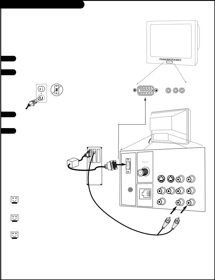
Hook Up a Computer to your TV
On some models, your new Zenith TV is furnished with the PCZTV scan converter, giving you a TV-size “computer monitor.” You may use the VGA and SVGA video format of either a PC or Macintosh 800 x 600 60Hz. And, because of multisync capability, you won’t have to change the video settings of your computer—your TV will adapt for you! Here is the basic setup as a monitor.
1 |
Make the basic connections as indicated. (Appearance of compo- |
|
nents may vary from those in the illustrations see page 13.) |
2 |
Plug in your TV. Do not plug it into a switched outlet. Your |
|
Presentation TV is designed to operate on standard current, 120- |
||
|
||
|
volt 60 Hertz AC. Do not attempt to operate it on DC Current. |
3 |
On the remote, press TV/VCR SOURCE repeatedly until |
|
“REAR COMPUTER SVGA NTSC OUT” (Rear Computer in) is dis- |
|
played, or “F COMPUTER SVGA” (Front Computer in) is displayed. |
4 |
Boot up your computer. As it warms up, the TV will adapt to your |
|
computer. |
Out to other
Monitor
ANTENNA
CABLE
"Video Mirror" |
Back of |
Cable |
Computer |
|
COMPUTER |
|
IN |
M.P.I.
Components may vary from those in the illustration. If you have a Macintosh, use the
2-row to 3-row DB15 adapter on their video connector.
On some notebook models you must locate the “display toggle key” and switch the display to “external.” Refer to the instructions for your computer.
You can also connect your computer to the Front input jacks panel; specify F COMPUTER SVGA in the Source menu; press TV/VCR SOURCE.
video in L audio R
TV back
S-VIDEO OUT |
S-VIDEO IN |
R- AUDIO- L |
|
VIDEO AUX IN |
R- AUDIO- L |
R |
|
|
AUDIO OUT |
|
R- AUDIO- L |
L |
COMPUTER |
|
AUDIO |
|
P A G E 1 2 |
206-3492-O |
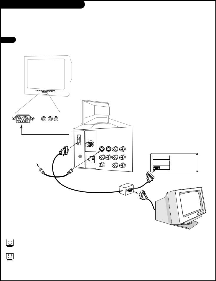
Hook Up a Computer to your TV
An accessory packet is included with all models. A 15-ft. cable with a “video mirror” is featured that provides signals to two monitors—your computer’s monitor and your Zenith TV—with a display.
1 |
Make the connections with the 15-ft. “video-mirror” cable as shown. Also refer |
|
to the preceding page for audio connections and “Using the monitor function.” |
TV back
video in L audio R
ANTENNA
CABLE
Actual appearance of
components may vary |
S-VIDEO OUT |
S-VIDEO IN R- AUDIO- L |
COMPUTER |
|
|
|
IN |
|
|
M.P.I. |
VIDEO AUX IN R- AUDIO- L |
|
R |
|
|
AUDIO OUT |
R- AUDIO- L |
|
L |
COMPUTER |
|
AUDIO |
Back of computer
Cable for "video mirror"
Video cable from monitor
Computer monitor
Your TV must be plugged in—not necessarily turned on—for the computer monitor to function.
You can ”Daisy Chain” other TVs via S-video loop and see the computer display on more TV sets (see page 11 for details).
206-3492-O |
P A G E 1 3 |

Remote Key Command Functions
Adjust the screen options while in Computer Mode
Note: The following only applies to those TVs equipped with PCZ Scan Conversion technology
While your Presentation TV is in Rear Computer Mode, the table below lists the commands used to make adjustments to the screen.
The following remote keys apply ONLY to the NUMBER keypad.
|
|
|
|
Remote Key |
Normal Mode |
Menu Mode |
Zoom Mode |
1* |
Enter Zoom Mode |
N/A |
†† Increase Zoom or |
|
|
|
Cancel Zoom Mode |
2 |
N/A |
N/A |
Pan Up |
3** |
Compress On/Off |
N/A |
Compress On/Off |
4 |
N/A |
Menu Adjust Down |
Pan Left |
5 |
Enter Menu Mode |
Cancel Menu Model |
Enter Menu Mode |
6 |
N/A |
Menu Adjust Up |
Pan Right |
7 |
†Auto Screen Size |
N/A |
N/A |
8 |
N/A |
Menu Select/Next |
Pan Down |
9 |
N/A |
N/A |
N/A |
0 |
Freeze/Thaw |
N/A |
Freeze/Thaw |
|
|
|
|
|
|
|
|
† Auto Size will adjust the computer image to match the TV Screen.
Use a full-screen computer display with high average brightness for best results.
*The image cannot be zoomed in Freeze Mode.
**Compress mode is not available in REAR COMPUTER SVGA as input. It is available in REAR COMPUTER NTSC OUT as input source.
†† If Zoom Mode is enabled it will cycle through: 1:1, 2:1, 3:1, 4:1, then back to 1:1 etc.
P A G E 1 4 |
206-3492-A |
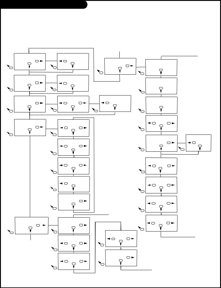
Remote Key Command Functions
Note: The following only applies to those TVs equipped with PCZ Scan Conversion technology.
The table below illustrates the menu structure for your Presentation TV while in Computer mode. As with the Remote Key Command Functions, menus are operated through the NUMBER keypad. Generally speaking, keys 4 and 6 adjust menu
options, key 8 cycles through menus and key 5 cancels all operations no matter what menu you are adjusting. Although menus are available in the Advanced mode, adjustments in this mode should only be made by a qualified service representative.
Menu Adjust:
H. SoftenOff
Adjust 6
8
Menu Adjust:
Zoom Cont: Remote
Adjust 6
8
Menu Adjust:
Zoom Level 2
Adjust 6
8
Menu Adjust:
Screen Size . . .
Adjust 6
8
Menu Adjust:
Manual Set . . .
Adjust 6
8
A
 Pressing this key will exit all Scan Card Menus.
Menu Adjust:
H. SoftenOn
4 Adjust
8
Menu Adjust:
Zoom Cont. Menu
4 Adjust
8
Menu Adjust:
Level 3
4 Adjust 6
8
Menu Size:
Out H-Center:77
4 |
Adjust |
6 |
|
8 |
|
Menu Size:
Out H-Width:99
4 Adjust 6
8
Menu Size:
Out V-Center:340
4 Adjust 6
8
Menu Size:
Out V-Height: 600
4 Adjust
8
Menu Size:
Store OK
Adjust 6
8
Menu Manual Set:
VGA Left: 0
|
Adjust |
6 |
|
8 |
|
Menu Manual Set: |
||
VGA Width: |
80 |
|
4 |
Adjust |
6 |
|
8 |
|
Menu Manual Set: |
||
VGA Top/4: |
5 |
|
4 |
Adjust |
6 |
|
8 |
|
A
Menu Adjust:
Advanced . . .
Adjust 6
8
Menu Adjust:
Zoom Level 4
4 Adjust
8
B
Menu Manual Set:
VGA Bot/4: 157
4 |
Adjust |
6 |
|
8 |
|
Menu Manual Set:
VGA Store |
0 |
Adjust |
6 |
8 |
|
Menu Advanced:
SW 18 HW |
6, 5 |
Adjust
8
Menu Advanced:
Total Lines 628
Adjust
8
Menu Advanced:
Vert. Freq 60
Adjust
8
Menu Advanced: |
|
|
Sense |
2 |
|
4 |
Adjust |
6 |
|
8 |
|
Menu Advanced: |
|
|
CR Character13 |
|
|
|
Adjust |
6 |
|
8 |
|
Menu Advanced: |
|
|
Clock width |
2 |
|
4 |
Adjust |
6 |
|
8 |
|
Menu |
Advanced: |
|
Clock Width B: 2
4 Adjust 6
8
Menu Advanced:
Settings 0
4 Adjust 6
8
Menu Advanced:
Eng Reset |
Off |
4 Adjust 6
8
B
C
Menu Advanced: CR character130
4 Adjust
8
C
206-3492-A |
P A G E 1 5 |
 Loading...