


Installation and Operating Guide | Warranty
Model Numbers | R45W47, R50W47, R57W47 | Projection TV
© Copyright 2004, LG Electronics USA, Inc.
Warning
Warning
WARNING
RISK OF ELECTRIC SHOCK
DO NOT OPEN
WARNING:
TO REDUCE THE RISK OF ELECTRIC SHOCK DO NOT REMOVE COVER (OR BACK). NO USER SERVICEABLE PARTS INSIDE. REFER TO QUALIFIED SERVICE PERSONNEL.
The lightning flash with arrowhead symbol, within an equilateral triangle, is intended to alert the user to the presence of uninsulated “dangerous voltage” within the product’s enclosure that may be of sufficient magnitude to constitute a risk of electric shock to persons.
The exclamation point within an equilateral triangle is intended to alert the user to the presence of important operating and maintenance (servicing) instructions in the literature accompanying the appliance.
WARNING:
TO PREVENT FIRE OR SHOCK HAZARDS, DO NOT EXPOSE THIS PRODUCT TO RAIN OR MOISTURE.
POWER CORD POLARIZATION:
CAUTION: TO PREVENT ELECTRIC SHOCK, MATCH WIDE BLADE OF PLUG TO WIDE SLOT, FULLY INSERT.
NOTE TO CABLE/TV INSTALLER:
This reminder is provided to call the CATV system installer’s attention to Article 820-40 of the National Electric Code (U.S.A.). The code provides guidelines for proper grounding and, in particular, specifies that the cable ground shall be connected to the grounding system of the building, as close to the point of the cable entry as practical.
REGULATORY INFORMATION:
This equipment has been tested and found to comply with the limits for a Class B digital device, pursuant to Part 15 of the FCC Rules. These limits are designed to provide reasonable protection against harmful interference when the equipment is operated in a residential installation. This equipment generates, uses and can radiate radio frequency energy and, if not installed and used in accordance with the instruction manual, may cause harmful interference to radio communications. However, there is no guarantee that interference will not occur in a particular installation. If this equipment does cause harmful interference to radio or television reception, which can be determined by turning the equipment off and on, the user is encouraged to try to correct the interference by one or more of the following measures:
•Reorient or relocate the receiving antenna.
•Increase the separation between the equipment and receiver.
•Connect the equipment into an outlet on a circuit different from that to which the receiver is connected.
•Consult the dealer or an experienced radio/TV technician for help.
Any changes or modifications not expressly approved by the party responsible for compliance could void the user’s authority to operate the equipment.
CAUTION:
Do not attempt to modify this product in any way without written authorization from Zenith Electronics. Unauthorized modification could void the user’s authority to operate this product.
COMPLIANCE:
The responsible party for this product’s compliance is: Zenith Electronics Corporation
1-201-816-2000
Marked and Distributed in the United States by LG Electronics U.S.A., Inc.
1000 Sylvan Avenue, Englewood Cliffs, NJ 07632 http://www.zenith.com
2 Projection TV

Safety Instructions
Safety Instructions
Important safeguards for you and your new product
Your product has been manufactured and tested with your safety in mind. However, improper use can result in electrical shock or fire hazards. To avoid defeating the safeguards that have been built into your new product, please read and observe the following safety points when installing and using your new product, and save them for future reference.
Observing the simple precautions discussed in this manual can help you get many years of enjoyment and safe operation that are built into your new product.
This product complies with all applicable U.S. Federal safety requirements, and those of the Canadian Standards Association.
1. Read Instructions |
9. Attachments |
All the safety and operating instructions should be read |
Do not use attachments not recommended by the product |
before the product is operated. |
manufacturer as they may cause hazards. |
2. Follow Instructions
All operating and use instructions should be followed.
3. Retain Instructions
The safety and operating instructions should be retained for future reference.
4. Heed Warnings
All warnings on the product and in the operating instructions should be adhered to.
5. Cleaning
Unplug this product from the wall outlet before cleaning. Do not use liquid cleaners or aerosol cleaners. Use a damp cloth for cleaning.
6. Water and Moisture
Do not use this product near water, for example, near a bath tub, wash bowl, kitchen sink, or laundry tub, in a wet basement, or near a swimming pool.
7. Accessories, Carts, and Stands
Do not place this product on a slippery or tilted surface, or on an unstable cart, stand, tripod, bracket, or table. The product may slide or fall, causing serious injury to a child or adult, and serious damage to the product. Use only with a cart, stand, tripod, bracket, or table recommended by the manufacturer, or sold with the product. Any mounting of the product should follow the manufacturer’s instructions, and should use a mounting accessory recommended by the manufacturer.
8. Transporting Product
A product and cart combination should be moved with care. Quick stops, excessive force, and uneven surfaces may cause the product and cart combination to overturn.
10. Ventilation
Slots and openings in the cabinet are provided for ventilation and to ensure reliable operation of the product and to protect it from overheating, and these openings must not be blocked or covered. The openings should never be blocked by placing the product on a bed, sofa, rug, or other similar surface. This product should not be placed in a built-in installation such as a bookcase or rack unless proper ventilation is provided or the manufacturer’s instructions have been adhered to.
11. Power Sources
This product should be operated only from the type of power source indicated on the marking label. If you are not sure of the type of power supply to your home, consult your product dealer or local power company. For products intended to operate from battery power, or other sources, refer to the operating instructions.
12. Power-Cord Polarization
This product is equipped with a wire grounding type plug, a plug having a third (grounding) pin. This plug will only fit into the grounding-type power outlet. This is a safety feature. If you are unable to insert the plug into the outlet, contact your electrician to replace your obsolete outlet. Do not defeat the safety purpose of the grounding-type plug.
13. Power-Cord Protection
Power-supply cords should be routed so that they are not likely to be walked on or pinched by items placed upon or against them, paying particular attention to cords at plugs, convenience receptacles, and the point where they exit from the product.
PORTABLE CART WARNING
Owner’s Manual 3
Safety Instructions
Safety Instructions continued
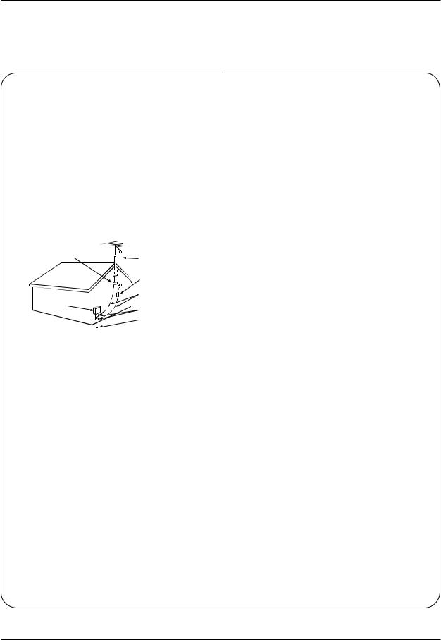
14. Outdoor Antenna Grounding
If an outside antenna or cable system is connected to the product, be sure the antenna or cable system is grounded so as to provide some protection against voltage surges and built-up static charges. Article 810 of the National Electrical Code (U.S.A.), ANSI/ NFPA 70 provides information with regard to proper grounding of the mast and supporting structure, grounding of the lead-in wire to an antenna discharge unit, size of grounding conductors, location of antenna-dis- charge unit, connection to grounding electrodes, and requirements for the grounding electrode.
Example of Grounding According to National Electrical Code Instructions
Ground Clamp
|
|
|
|
Antenna Lead in Wire |
|
|
|
|
Antenna Discharge Unit |
|
|
|
|
(NEC Section 810-20) |
|
|
|
|
Grounding Conductor |
Electric Service |
|
|
|
(NEC Section 810-21) |
|
|
|
|
|
Equipment |
|
|
|
Ground Clamps |
|
|
|
|
|
|
|
|
|
Power Service Grounding |
|
|
|
|
Electrode System (NEC |
|
|
|
|
Art 250, Part H) |
NEC - National Electrical Code
15. Lightning
For added protection for this product (receiver) during a lightning storm, or when it is left unattended and unused for long periods of time, unplug it from the wall outlet and disconnect the antenna or cable system. This will prevent damage to the product due to lightning and power-line surges.
16. Power Lines
An outside antenna system should not be located in the vicinity of overhead power lines or other electric light or power circuits, or where it can fall into such power lines or circuits. When installing an outside antenna system, extreme care should be taken to keep from touching such power lines or circuits as contact with them might be fatal.
17. Overloading
Do not overload wall outlets and extension cords as this can result in a risk of fire or electric shock.
18. Object and Liquid Entry
Never push objects of any kind into this product through openings as they may touch dangerous voltage points or short-out parts that could result in a fire or electric shock. Never spill liquid of any kind on the product.
19. Servicing
Do not attempt to service this product yourself as opening or removing covers may expose you to dangerous voltage or other hazards. Refer all servicing to qualified service personnel.
20. Damage Requiring Service
Unplug this product from the wall outlet and refer servicing to qualified service personnel under the following conditions:
a.If the power-supply cord or plug is damaged.
b.If liquid has been spilled, or objects have fallen into the product.
c.If the product has been exposed to rain or water.
d.If the product does not operate normally by following the operating instructions. Adjust only those controls that are covered by the operating instructions as an improper adjustment of other controls may result in damage and will often require extensive work by a qualified technician to restore the product to its normal operation.
e.If the product has been dropped or the cabinet has been damaged.
f.If the product exhibits a distinct change in performance.
21. Replacement Parts
When replacement parts are required, be sure the service technician has used replacement parts specified by the manufacturer or have the same characteristics as the original part. Unauthorized substitutions may result in fire, electric shock, or other hazards.
22. Safety Check
Upon completion of any service or repairs to this product, ask the service technician to perform safety checks to determine that the product is in proper operating condition.
23. Wall or Ceiling Mounting
The product should be mounted to a wall or ceiling only as recommended by the manufacturer. The product may slide or fall, causing serious injury to a child or adult, and serious damage to the product.
24. Heat
The product should be situated away from heat sources such as radiators, heat registers, stoves, or other products (including amplifiers) that produce heat.
4 Projection TV

Contents
Contents
Warnings . . . . . . . . . . . . . . . . . . . . . . . . . . . . . . . . . . . . .2
Safety Instructions . . . . . . . . . . . . . . . . . . . . . . . . . . . . .3~4
Introduction
Controls . . . . . . . . . . . . . . . . . . . . . . . . . . . . . . .6
Connection Options . . . . . . . . . . . . . . . . . . . . . .7
Remote Control Key Functions . . . . . . . . . . . . . .8
Installation |
|
External Equipment Connections . . . . . . . . . . . |
9~12 |
Antenna Connection . . . . . . . . . . . . . . . . . . . |
. . .9 |
VCR Setup / Cable TV (CATV) Setup . . . . . . |
. .10 |
Monitor Out Setup . . . . . . . . . . . . . . . . . . . . |
. .10 |
External A/V Source Setup . . . . . . . . . . . . . . |
. .11 |
DVD Setup / External Stereo . . . . . . . . . . . . . |
. .11 |
HDSTB Setup / Digital Audio Output . . . . . . . |
. .12 |
Dolby Digital Audio Connection . . . . . . . . . . . |
. .12 |
EZ Notice; Make A/V Connection . . . . . . . . . |
. .12 |
Operation
TV Operation Overview . . . . . . . . . . . . . . . . . . . .13
On-screen Menus Language Selection . . . . . . . . .13
Setup Menu Options
EZ Scan (Channel Search) . . . . . . . . . . . . . . . .14
Channel Edit . . . . . . . . . . . . . . . . . . . . . . . . . . .14
DTV Signal Strength . . . . . . . . . . . . . . . . . . . . .15
Channel Labels Setup . . . . . . . . . . . . . . . . . . . .15
Main Picture Source Selection . . . . . . . . . . . . .15
Video Menu Options
EZ Picture . . . . . . . . . . . . . . . . . . . . . . . . . . . .16
Manual Picture Control (Off Option) . . . . . . . . .16
Color Temperature Control . . . . . . . . . . . . . . . .16
Z-View . . . . . . . . . . . . . . . . . . . . . . . . . . . . . . .17
Video Preset . . . . . . . . . . . . . . . . . . . . . . . . . .17
Audio Menu Options
Audio Language . . . . . . . . . . . . . . . . . . . . . . . .18
EZ SoundRite / EZ Sound . . . . . . . . . . . . . . . . .18
Manual Sound Control (Off Option) . . . . . . . . . .18
Stereo/SAP Broadcasts Setup . . . . . . . . . . . . .19
Front Surround . . . . . . . . . . . . . . . . . . . . . . . . .19
TV Speakers Setup . . . . . . . . . . . . . . . . . . . . . .19
Time Menu Options |
|
|
|
Auto Clock Setup . . . . . . . . . . . . . . . . |
. . . . |
. . |
.20 |
Manual Clock Setup . . . . . . . . . . . . . . |
. . . . |
. . . |
20 |
On/Off Timer Setup . . . . . . . . . . . . . . |
. . . . |
. . . |
20 |
Sleep Timer / Auto Off . . . . . . . . . . . . . |
. . . . |
. . . |
21 |
Option Menu Features |
|
|
|
Aspect Ratio Control . . . . . . . . . . . . . . |
. . . . |
. . . |
22 |
Caption . . . . . . . . . . . . . . . . . . . . . . . . |
. . . . |
. . . |
22 |
Caption Mode . . . . . . . . . . . . . . . . . . . |
. . . . |
. . . |
23 |
Caption Option . . . . . . . . . . . . . . . . . . |
. . . . |
. . . |
23 |
VM (Velocity Modulation) . . . . . . . . . . |
. . . . |
. . . |
24 |
Auto Convergence . . . . . . . . . . . . . . . |
. . . . |
. . . |
24 |
EZ Demo . . . . . . . . . . . . . . . . . . . . . . |
. . . . |
. . . |
24 |
Lock Menu Options |
|
|
|
Parental Lock Setup . . . . . . . . . . . . . . |
. . . . |
. . . |
26 |
PIP (Picture-in-Picture)/POP/Twin Picture |
|
|
|
Watching the PIP/POP/Twin Picture . . |
. . . . |
. . .. |
27 |
Selecting an Input Signal Source for PIP/Twin Picture . . |
27 |
||
Swapping PIP/Twin Picture . . . . . . . . . |
. . . . |
. . . |
27 |
TV Program Selection for PIP/Twin Picture . |
. . . |
27 |
|
Moving the PIP Sub Picture . . . . . . . . |
. . . . . |
. . |
28 |
Adjusting Main and Sub Picture Sizes for Twin Picture |
.28 |
||
POP (Picture-out-of-Picture: Channel Scan) |
. . .28 |
||
Programming the Remote . . . . . . . . . . . . . . . |
. . . . . |
. . |
29 |
Programming Codes . . . . . . . . . . . . . . . . . . . |
. . . . |
30~31 |
|
Troubleshooting Checklist . . . . . . . . . . . . . . . |
. . . . |
32~33 |
|
Maintenance . . . . . . . . . . . . . . . . . . . . . . . . . . |
. . . . . |
. . |
34 |
Product Specifications . . . . . . . . . . . . . . . . . . |
. . . . . |
. . |
34 |
Notes . . . . . . . . . . . . . . . . . . . . . . . . . . . . . |
. . . . . |
. . |
35 |
Warranty . . . . . . . . . . . . . . . . . . . . . . . . . . . . . |
Back cover |
||
Setup and Operation Checklist
Setup and Operation Checklist
(See pages 11~15 for available connection and operational setup options.)
1.Unpack TV and all accessories.
2.Connect all external video and audio equipment. see pages 9 ~ 12.
3Install batteries in remote control. See page 8.
4.Turn TV on. See page 13.
5.Turn video source equipment on.
6.Select viewing source for TV. See page 15.
7.Fine-tune source image and sound to your personal preference or as required by source.
See pages 16 ~ 19.
8.Additional features set up See Contents above.
After reading this manual, keep it handy for future reference.
Owner’s Manual 5

Introduction
Introduction
Controls
tv/video menu enter  mute
mute 
 vol
vol 
 ch
ch
|
MUTE Button |
CHANNEL (E, D) Buttons |
|
TV/VIDEO Button |
|
|
ENTER Button |
VOLUME (F,G) Buttons |
|
|
|
|
MENU Button |
|
|
Power Standby Indicator |
|
|
Illuminates brightly when the TV is in standby mode. |
|
|
Dims when the TV is switched on. |
|
ON/OFF Button |
Remote Control Sensor |
|
6 Projection TV

Introduction
Connection Options
Owner’s Manual 7
Introduction
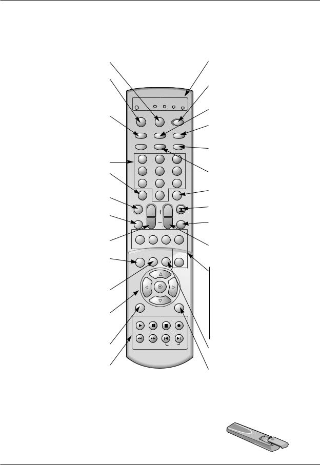
Remote Control Key Functions
- When using the remote control, aim it at the remote control sensor on the TV.
LIGHT
Illuminates the remote control buttons.
MODE
Selects the remote operating mode: TV, VCR, Cable Box, DVD, or Satellite.
Select other operating modes, for the remote to operate external devices.
TV/VIDEO
Selects: DTV, Analog, Video1-2,
Front Video, Video4, Component 1-2,
and DVI input sources.
tv |
vcr cable dvd sat |
mode light power
tv/video front comp/dvi
ratio signal freeze
RATIO 

Changes the aspect ratio.
NUMBER buttons |
1 |
2 |
3 |
|
|
|
|
||
DASH |
4 |
5 |
6 |
|
Used to enter a program number for multiple |
7 |
8 |
9 |
|
program channels such as 2— 1,2— 2,etc. |
||||
|
|
|
||
MUTE |
dash(-) |
0 |
flashbk |
|
mute |
surf |
|||
Switches the sound on or off. |
|
|||
|
|
|
||
AUDIO |
audio |
|
video |
|
Selects MTS sound: Mono, Stereo, and SAP. |
|
|||
|
vol |
ch |
||
Change the audio language in DTV mode. |
|
|||
pip |
pipch- |
pipch+ pip input |
||
|
VOLUME UP/DOWN |
|
|
|
|
Increases/decreases the sound level. |
|
|
|
|
INFO |
info |
timer |
cc |
swap |
|
|
|||
|
|
|
|
|
When you watch the TV, displays informa- |
|
|
|
|
tion on top of the screen. Not available in |
|
|
|
|
Component 1-2, RGB and DVI mode. |
|
|
|
|
TIMER
Lets you select the amount of time before your TV turns itself off automatically.
THUMBSTICK (Up/Down/Left/Right/OK)
Allows you to navigate the on-screen menus and adjust the system settings to your preference.
MENU
Brings up the main menu to the screen.
VCR/DVD BUTTONS
Control some video cassette recorders or DVD player ("RECORD" button is not available for DVD player).
menu |
exit |
play pause stop record
rew ff
skip
MODE INDICATOR LIGHTS
Show active remote mode every time any button is pressed.
POWER
Turns your TV or any other programmed equipment on or off, depending on mode.
FRONT
Selects the front video input sources.
COMP/DVI
Selects: Component 1-2, and DVI input sources.
FREEZE
Freezes the currently-viewed picture. Main picture is frozen in PIP/Twin picture mode.
SIGNAL
Displays the digital signal strength.
FLASHBK
Tunes to the last channel viewed.
SURF
Use to scroll the Surf channel list.
VIDEO
Adjusts the factory preset picture according to the room.
CHANNEL UP/DOWN
Selects available channels found with EZ scan.
PIP
Switches between PIP, POP (Picture-out-of- Picture) and Twin picture modes.
PIPCH-/PIPCH+
Changes to next higher/lower PIP channel.
PIP INPUT
Selects the input source for the sub picture.
SWAP
Exchanges the PIP/main images.
CC
Select a closed caption: Off, EZ Mute, and On.
EXIT
Clears all on-screen displays and returns to TV viewing from any menu.
Installing Batteries
•Open the battery compartment cover on the back side and install the batteries matching correct polarity (+ with +, - with -).
•Install two 1.5V AA batteries. Don’t mix old or used batteries with new ones.
Replace cover.
8 Projection TV

Installation
Antenna Connection
Connections for Analog and Digital TV signals provided on one antenna
a Cable Box Connections
antenna direction if needed.
Multi-family Dwellings/Apartments (Connect to wall antenna socket)
Wall Antenna
Socket
ANTENNA1 |
ANTENNA 2 |
|
|
Bronze Wire |
|
RF Coaxial Wire (75 ohm) |
|
VHF Antenna |
Turn clockwise to tighten. |
|
|
||
UHF Antenna |
|
|
|
|
Bronze Wire |
|
Outdoor |
|
|
Antenna |
Be careful not to bend the bronze wire when |
Single-family Dwellings /Houses |
connecting the antenna. |
|
(Connect to wall jack for outdoor antenna) |
|
|
|
|
• In a poor signal area to improve picture quality, purchase |
ANTENNA1 ANTENNA 2 |
|
and install a signal amplifier. |
|
|
|
|
|
• If the antenna needs to be split for two TV’s, install a “2- |
|
|
Way Signal Splitter” in the connections. |
|
|
• If the antenna is not installed properly, contact your deal- |
|
|
er for assistance. |
|
Signal |
|
|
Amplifier |
|
Connections for Analog and Digital TV signals provided on two separate antennas
Wall Antenna |
Bronze Wire |
ANTENNA1 ANTENNA 2 |
|
||
Socket |
RF Coaxial Wire (75 ohm) |
|
|
|
Analog Antenna
Turn clockwise to tighten.
Digital Antenna
Bronze Wire
NOTE: If you are not sure of the type of signal(s) you are receiving, let EZ Scan complete all the channel signal-type searches.
The TV will let you know when the analog, cable, and digital channel scans are complete.
Owner’s Manual 9
Installation
VCR Setup
2
1
|
|
|
|
|
|
|
VCR |
|
|
|
|
Cable TV (CATV) Setup |
|
|
|
|
|
|
|
|
|
|
|
from a local provider and |
|
|
|
|
|
|
|
|
|
|
|
you can watch cable TV |
A |
|
|
|
|
|
|
|
|
|
|
|
C |
|
|
|
|
|
|
|
|
|
|
TV programming unless a |
L |
|
|
|
|
|
|
|
|
|
|
R |
|
|
|
|
|
|
|
|
|
|
|
|
I |
|
|
|
|
|
|
|
|
|
|
|
B |
|
|
|
|
|
|
|
|
|
|
box is connected to the TV. |
A |
|
|
|
|
|
|
|
|
|
|
T |
|
|
|
|
|
|
|
|
|
|
|
N |
|
|
|
|
|
|
|
|
|
|
|
|
I |
ANTENNA1 |
ANTENNA 2 |
|
|
|
|
|
|
|
|
before you can receive |
O |
|
|
|
|
|
|
|
|||
AUDIO OUTPUT |
|
|
|
|
|
|
|
|
|
|
|
|
DIGITAL |
|
|
|
|
|
|
|
|
|
|
|
OPTICAL |
|
|
|
|
|
|
|
|
|
|
cable TV service, contact your |
AUDIO INPUT1 |
|
|
|
|
|
|
|
|
|
|
|
DIGITAL |
|
|
|
|
|
|
|
|
|
|
. |
OPTICAL |
|
|
COMPONENT1 |
COMPONENT2 |
|
|
|
|
|
|
(COMPONENT1) |
|
(480i/480p/720p/1080i) |
|
|
|
|
|
|
|||
|
|
|
A |
R |
R |
|
|
|
|
|
|
|
DIGITAL |
|
U |
|
|
|
|
|
|
|
|
|
AUDIO INPUT2 |
|
D |
|
|
|
|
|
|
|
|
|
OPTICAL |
|
I |
|
|
|
|
MONITOR |
|
|
|
on cable box. |
(DVI) |
|
O |
L |
L |
|
|
|
|
||
|
|
VIDEO L AUDIO R |
OUTPUT |
CENTER |
|
||||||
|
|
|
|
|
INPUT |
SPEAKER |
|
||||
|
|
|
|
|
|
V |
|
|
|||
|
|
|
|
|
S-VIDEO |
|
|
|
|
||
|
|
|
|
|
|
|
I |
|
|
MODE INPUT |
|
|
|
|
|
PR |
PR |
|
I |
|
|
|
|
as the output channel |
DVI |
|
|
|
N |
D |
|
|
|
||
|
|
|
|
S1 |
1 |
E |
|
|
|
||
|
|
|
V |
|
|
|
O |
|
|
|
|
|
-HDTV |
|
|
|
|
I |
|
|
|
V |
|
|
|
I |
|
|
|
|
|
|
A |
||
|
INPUT |
|
D |
PB |
PB |
|
N |
A |
|
|
I |
|
|
|
|
2 |
U |
|
|
A |
|||
|
|
|
E |
|
|
S2 |
L |
L |
B |
||
or with the cable box remote |
|
|
|
|
|
D |
L |
||||
|
|
O |
|
|
|
|
|
E |
|||
|
|
|
Y |
Y |
|
N |
O |
|
|
D |
|
|
|
|
|
|
|
|
I |
I |
|
|
A |
|
|
|
|
|
|
|
|
|
|
U |
|
|
|
|
|
|
|
|
4 |
|
|
|
I |
|
|
|
|
|
|
|
MONO |
|
R |
R |
O |
|
|
|
|
|
|
|
|
|
|
|
|
|
Cable Box |
1 |
|
|
|
|
2 |
|
|
|
|
jacks on Cable Box to the corre- |
|
|
|
|
|
|
|
|
|
||
match the jack colors (Video |
|
|
|
|
(R) AUDIO (L) |
VIDEO |
|
|
|
|
|
Audio Right = red). |
|
|
OUTPUT |
|
|
|
|
|
|
|
|
|
|
3 |
4 |
|
|
|
|
|
|
|
|
|
|
|
SWITCH TV |
|
|
|
|
|
|
|
|
tv/video button on the remote |
|
RF Cable |
|
VCR |
|
|
|
|
|
|
|
|
|
|
|
|
|
|
|
|
|
|
|
Video 1 input source) |
|
|
|
|
|
|
|
|
|
|
|
the remote control for cable box. |
|
|
|
|
|
|
|
|
|
|
|
Monitor Out Setup
|
|
|
|
MONITOR |
|
|
output capability which allows you to |
|
VIDEO |
L AUDIO R |
OUTPUT |
CENTER |
|
INPUT |
SPEAKER |
|||||
I |
|
I |
||||
|
S-VIDEO |
|
|
|
||
|
|
|
|
V |
MODE INPUT |
|
|
|
|
|
|
||
. |
|
N |
|
D |
|
|
S1 |
1 |
|
E |
|
||
|
|
O |
|
I |
|
|
|
V |
|
|
|
A |
|
N |
A |
|
|
I |
2 |
U |
|
|
A |
L |
L |
B |
||
S2 |
D |
L |
||
|
|
E |
monitor to the TV’s MONITOR OUTPUT. |
4 |
|
I |
|
A |
|
|
|
I |
||
|
I |
|
O |
|
U |
|
N |
|
|
D |
|
the second TV or monitor for further |
|
MONO |
R |
R |
O |
|
|
|
|
||
|
|
|
|
|
|
s input settings. |
|
|
|
|
|
input sources cannot be used for
S-VIDEO
IN
(R) AUDIO (L) |
VIDEO |
10 Projection TV
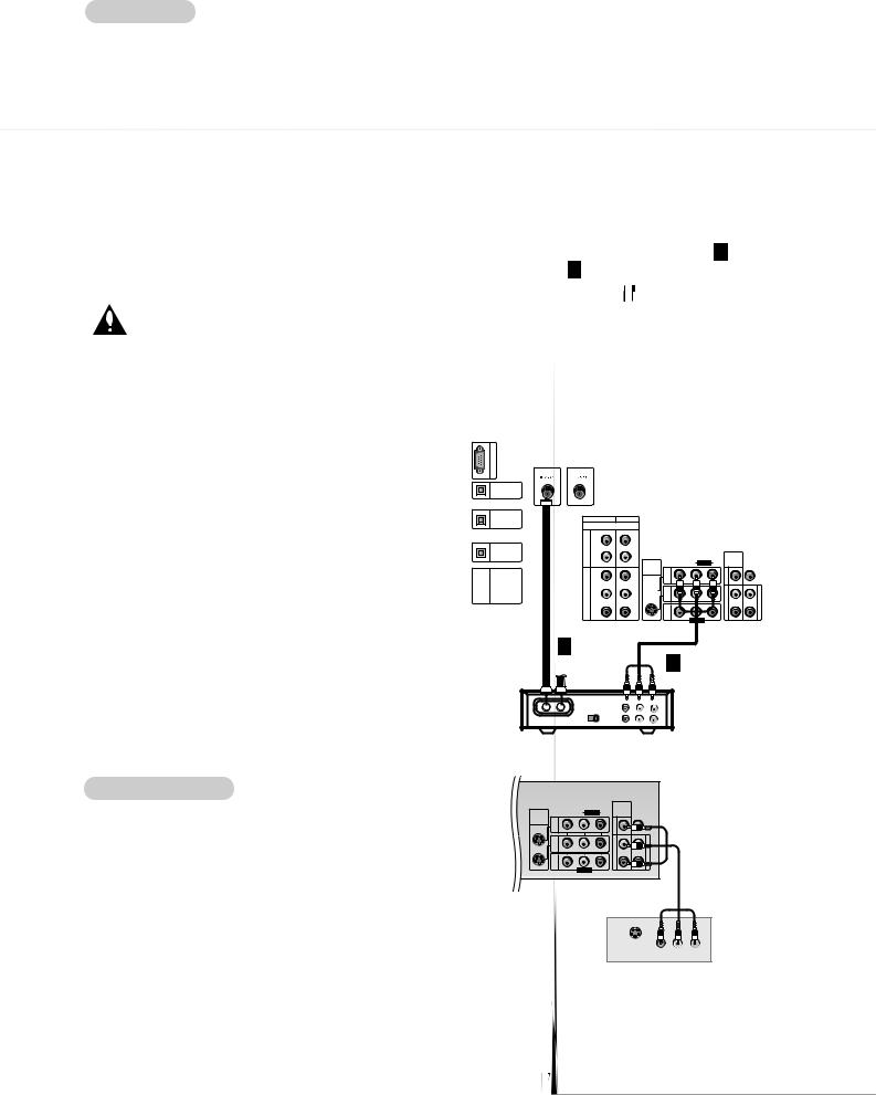
External A/V Source Setup
from the external A/V jacks on the TV.
match the jack and Audio Right =
button on the
Video 1 input
. Refer to
DVD Setup
better
Component ports on the TV
Video output ports on DVD player
Y |
PB |
PR |
Y |
Pb |
Pr |
Y |
B-Y R-Y |
|
Y |
Cb |
Cr |
Y |
PB |
PR |
Installation
|
COMPONENT1 |
COMPONENT2 |
|
|
|
|
|
|
|
|
(480i/480p/720p/1080i) |
|
|
|
|
|
|
|
|
A |
R |
R |
|
|
|
|
|
|
|
U |
|
|
|
|
|
|
|
|
|
D |
|
|
|
|
|
|
|
|
|
I |
|
|
|
|
|
MONITOR |
|
|
|
O |
L |
L |
|
|
|
|
|
||
S-VIDEO |
VIDEO L AUDIO |
R |
OUTPUT |
CENTER |
|
||||
|
|
|
SPEAKER |
|
|||||
|
|
|
INPUT |
I |
|
V |
|
MODE INPUT |
|
|
PR |
PR |
|
|
I |
|
|
|
|
|
|
N |
|
D |
|
|
|
||
|
|
|
S1 |
1 |
|
E |
|
|
|
V |
|
|
|
|
O |
|
|
|
|
|
|
|
I |
|
|
|
|
V |
|
I |
|
|
|
|
|
|
|
R |
|
|
|
|
|
|
|
|
|
|
A |
D |
PB |
PB |
|
N |
|
A |
|
|
I |
|
2 |
|
U |
|
|
A |
|||
E |
|
|
S2 |
|
L |
L |
B |
||
|
|
|
|
D |
L |
||||
O |
|
|
|
|
|
|
E |
||
|
|
|
I |
|
I |
|
|
|
|
|
|
|
|
|
|
|
A |
||
|
Y |
Y |
|
N |
|
O |
|
|
D |
|
|
|
|
4 |
|
|
|
|
I |
|
|
|
|
|
|
|
R |
R |
O |
MONO
R AUDIO L |
VIDEO |
Owner’s Manual 11
 Loading...