


HDV420

© Copyright 2002, Zenith Electronics Corporation
Installation and Operating Guide | Warranty
Model Number | HDV420 | High Definition Television Receiver
2
Safety Precautions
WARNING
TO PREVENT FIRE OR SHOCK HAZARDS, DO NOT EXPOSE THIS PRODUCT TO RAIN OR MOISTURE.
WARNING: Do not install this equipment in a confined space such as a book case or similar unit.
CAUTION: TO PREVENT ELECTRIC SHOCK, MATCH WIDE BLADE OF PLUG TO WIDE SLOT AND FULLY INSERT.
ATTENTION: POUR ÉVITER LES CHOC ÉLECTRIQUES, INTRODUIRE LA LAME LA PLUS LARGE DE LA FICHE DANS LA
BORNE CORRESPONDANTE DE LA PRISE ET POUSSER JUSQU’AU FOND.
NOTE TO CABLE/TV INSTALLER
This reminder is provided to call the cable TV system installer’s attention to Article 820-40 of the National Electric Code (U.S.A.).
The code provides guidelines for proper grounding and, in particular, specifies that the cable ground shall be connected to the
grounding system of the building, as close to the point of the cable entry as practical.
REGULATORY INFORMATION: FCC Part 15
This product has been tested and found to comply with the limits for a Class B digital device, pursuant to Part 15 of the FCC
Rules. These limits are designed to provide reasonable protection against harmful interference when the product is operated in a
residential installation. This product generates, uses and can radiate radio frequency energy and, if not installed and used in
accordance with the instruction manual, may cause harmful interference to radio communications. However, there is no guarantee
that interference will not occur in a particular installation. If this product does cause harmful interference to radio or television
reception, which can be determined by turning the product off and on, the user is encouraged to try to correct the interference by
one or more of the following measures:
• Reorient or relocate the receiving antenna.
• Increase the separation between the product and receiver.
• Connect the product into an outlet on a circuit different from that to which the receiver is connected.
• Consult the dealer or an experienced radio/TV technician for help.
COMPLIANCE: The responsible party for this product’s compliance is:
Zenith Electronics Corporation, 2000 Millbrook Drive, Lincolnshire, IL, 60069, USA Phone: 1-847-941-8000
CAUTION
DO NOT ATTEMPT TO MODIFY THIS PRODUCT IN ANY WAY WITHOUT WRITTEN AUTHORIZATION FROM ZENITH ELECTRONICS
CORPORATION. UNAUTHORIZED MODIFICATION COULD VOID THE USER’S AUTHORITY TO OPERATE THIS PRODUCT.
THIS EQUIPMENT IS INTENDED TO RECEIVE AND DECODE SIGNALS TRANSMITTED ACCORDING TO ATSC DIGITAL
TELEVISION STANDARD A/53, SPECIFICATION AND IS INTENDED TO BE USED WITH AN APPROPRIATE ANTENNA AND
DISPLAY DEVICE THAT YOU MUST PROVIDE.
CAUTION
RISK OF ELECTRIC SHOCK
DO NOT OPEN
THE LIGHTNING FLASH WITH ARROWHEAD SYMBOL, WITHIN AN EQUILATERAL TRIANGLE, IS INTENDED
TO ALERT THE USER TO THE PRESENCE OF UNINSULATED “DANGEROUS VOLTAGE” WITHIN THE PROD-
UCT’S ENCLOSURE THAT MAY BE OF SUFFICIENT MAGNITUDE TO CONSTITUTE A RISK OF ELECTRIC
SHOCK TO PERSONS.
THE EXCLAMATION POINT WITHIN AN EQUILATERAL TRIANGLE IS INTENDED TO ALERT THE USER TO THE
PRESENCE OF IMPORTANT OPERATING AND MAINTENANCE (SERVICING) INSTRUCTIONS IN THE LITERA-
TURE ACCOMPANYING THE APPLIANCE.
CAUTION:
TO REDUCE THE RISK OF ELECTRONIC SHOCK DO NOT REMOVE
COVER (OR BACK). NO USER SERVICEABLE PARTS INSIDE.
REFER TO QUALIFIED SERVICE PERSONNEL.
INTRODUCTION
3
IMPORTANT SAFETY INSTRUCTIONS
1. Read these instructions. - All these safety and oper-
ating instructions should be read before the product is
operated.
2. Keep these instructions. - The safety, operating and
use instructions should be retained for future refer-
ence.
3. Heed all warnings. - All warnings on the product and
in the operating instructions should be adhered to.
4. Follow all instructions. - All operating and use
instructions should be followed.
5. Do not use this apparatus near water. – For exam-
ple: near a bath tub, wash bowl, kitchen sink, laundry
tub, in a wet basement; near a swimming pool; etc.
6. Clean only with dry cloth. – Unplug this product from
the wall outlet before cleaning. Do not use liquid
cleaners.
7.
Do not block any ventilation openings. Install in
accordance with the manufacturer’s instructions. -
Slots and openings in the cabinet are provided for
ventilation, to ensure reliable operation of the product,
and to protect it from over- heating. The openings
should never be blocked by placing the product on a
bed, sofa, rug or other similar surface. This product
should not be placed in a built-in installation such as a
bookcase or rack unless proper ventilation is provided
and the manufacturer’s instructions have been
adhered to.
8. Do not install near any heat sources such as radi-
ators, heat registers, stoves, or other apparatus
(including amplifiers) that produce heat.
9.
Do not defeat the safety purpose of the polarized or
grounding-type plug. A polarized plug has two
blades with one wider than the other. A grounding
type plug has two blades and a third grounding
prong. The wide blade or the third prong are pro-
vided for your safety. If the provided plug does not
fit into your outlet, consult an electrician for
replacement of the obsolete outlet.
10. Protect the power cord from being walked on or
pinched particularly at plugs, convenience
receptacles, and the point where they exit from
the apparatus.
11. Only use attachments/accessories specified by
the manufacturer.
12. Use only the cart, stand, tripod, bracket, or table
specified by the manufacturer, or sold with appa-
ratus. When a cart is used, use caution when
moving the cart/ apparatus combination to avoid
injury from tip-over.
13. Unplug this apparatus during lightning storms or
when unused for long periods of time.
14.
Refer all servicing to qualified service personnel.
Servicing is required when the apparatus has
been damaged in any way, such as power-
supply cord or plug is damaged, liquid has been
spilled or objects have fallen into the apparatus,
the apparatus has been exposed to rain or mois-
ture, does not operate normally, or has been
dropped.
CAUTION: PLEASE READ AND OBSERVE ALL WARNINGS AND INSTRUCTIONS IN THIS INSTALLATION
AND OPERATING GUIDE AND THOSE MARKED ON THE UNIT. RETAIN THIS GUIDE FOR
FUTURE REFERENCE.
This set has been designed and manufactured to assure personal safety. Improper use can result in electric shock
or fire hazard. The safeguards incorporated in this unit will protect you if you observe the following procedures for
installation, use, and servicing.
This unit does not contain any parts that can be repaired by the user.
DO NOT REMOVE THE CABINET COVER, OR YOU MAY BE EXPOSED TO DANGEROUS VOLTAGE. REFER
SERVICING TO QUALIFIED SERVICE PERSONNEL ONLY.
4
Table of Contents
Introduction
Safety Precautions . . . . . . . . . . . . . . . . . . . . . . . . . 2
SAFETY INSTRUCTIONS. . . . . . . . . . . . . . . . . . . . . 3
Table of Contents . . . . . . . . . . . . . . . . . . . . . . . . . . 4
Front Panel . . . . . . . . . . . . . . . . . . . . . . . . . . . . . . . 5
Remote Control . . . . . . . . . . . . . . . . . . . . . . . . . . . . 6
Rear Panel . . . . . . . . . . . . . . . . . . . . . . . . . . . . . . . . 7
Preparation
Unpacking . . . . . . . . . . . . . . . . . . . . . . . . . . . . . . . . 8
Connections . . . . . . . . . . . . . . . . . . . . . . . . . . . . 9-13
Connecting to an Antenna . . . . . . . . . . . . . . . . . . 9
Connecting to an Analog monitor . . . . . . . . . . . . 10
Connecting to a HD monitor (YPbPr type). . . . . . 11
Connecting to a HD monitor (RGB type). . . . . . . 12
Connecting to a VCR . . . . . . . . . . . . . . . . . . . . . 13
Connecting to an Amplifier (Receiver). . . . . . . . . 14
Operation
Menu Operation . . . . . . . . . . . . . . . . . . . . . . . . . . . 15
SETUP Settings . . . . . . . . . . . . . . . . . . . . . . . . 16-17
EZ Scan (Channel Search) . . . . . . . . . . . . . . . . 16
Ch. Edit (Channel Edit) . . . . . . . . . . . . . . . . . . . 16
DTV Signal . . . . . . . . . . . . . . . . . . . . . . . . . . . . 17
Channel Label . . . . . . . . . . . . . . . . . . . . . . . . . . 17
AUDIO Settings . . . . . . . . . . . . . . . . . . . . . . . . . . . 18
Audio Language. . . . . . . . . . . . . . . . . . . . . . . . . 18
Audio Variable . . . . . . . . . . . . . . . . . . . . . . . . . . 18
CAPTION Settings . . . . . . . . . . . . . . . . . . . . . . 19-20
Caption Settings General Operation . . . . . . . . . . 19
DTV Caption . . . . . . . . . . . . . . . . . . . . . . . . . . . 19
Size . . . . . . . . . . . . . . . . . . . . . . . . . . . . . . . . . . 19
Font. . . . . . . . . . . . . . . . . . . . . . . . . . . . . . . . . . 19
Foreground Color. . . . . . . . . . . . . . . . . . . . . . . . 19
FG (Foreground) Opacity . . . . . . . . . . . . . . . . . . 20
Background Color . . . . . . . . . . . . . . . . . . . . . . . 20
BG (Back Ground) Opacity. . . . . . . . . . . . . . . . . 20
Edge Type . . . . . . . . . . . . . . . . . . . . . . . . . . . . . 20
Edge Color . . . . . . . . . . . . . . . . . . . . . . . . . . . . 20
SPECIAL Settings. . . . . . . . . . . . . . . . . . . . . . . 21-22
Clock . . . . . . . . . . . . . . . . . . . . . . . . . . . . . . . . . 21
Language . . . . . . . . . . . . . . . . . . . . . . . . . . . . . 21
EZ Demo . . . . . . . . . . . . . . . . . . . . . . . . . . . . . . 21
Aspect Ratio . . . . . . . . . . . . . . . . . . . . . . . . . . . 22
LOCK Settings . . . . . . . . . . . . . . . . . . . . . . . . . 23-29
Lock System . . . . . . . . . . . . . . . . . . . . . . . . . . . 23
Set Password . . . . . . . . . . . . . . . . . . . . . . . . . . 24
Select Country . . . . . . . . . . . . . . . . . . . . . . . . . . 24
Block Ch. (Channel). . . . . . . . . . . . . . . . . . . . . . 25
Movie Rating . . . . . . . . . . . . . . . . . . . . . . . . . . . 25
TV Rating-Children . . . . . . . . . . . . . . . . . . . . . . 26
TV Rating-General . . . . . . . . . . . . . . . . . . . . . . . 27
TV Rating-English . . . . . . . . . . . . . . . . . . . . . . . 28
TV Rating-French. . . . . . . . . . . . . . . . . . . . . . . . 29
Reference
Programming the Remote Control for Other Devices
. . 30
Remote Control Codes for Other Devices
. . . . . 31-32
Troubleshooting . . . . . . . . . . . . . . . . . . . . . . . . . . 33
Specifications . . . . . . . . . . . . . . . . . . . . . . . . . . . . 34
Warranty . . . . . . . . . . . . . . . . . . . . . . . . . Back Cover
About the symbols for instructions
Indicates hazards likely to cause harm to the unit
itself or other material damage.
Indicates special operating features of this unit.
Indicates tips and hints for making the task easier.
Manufactured under license from Dolby Laboratories. Dolby,
and the double-D symbol are trademarks of Dolby
Laboratories. Confidential unpublished works. Copyright
1992-1997 Dolby Laboratories. All rights reserved.
INTRODUCTION
5
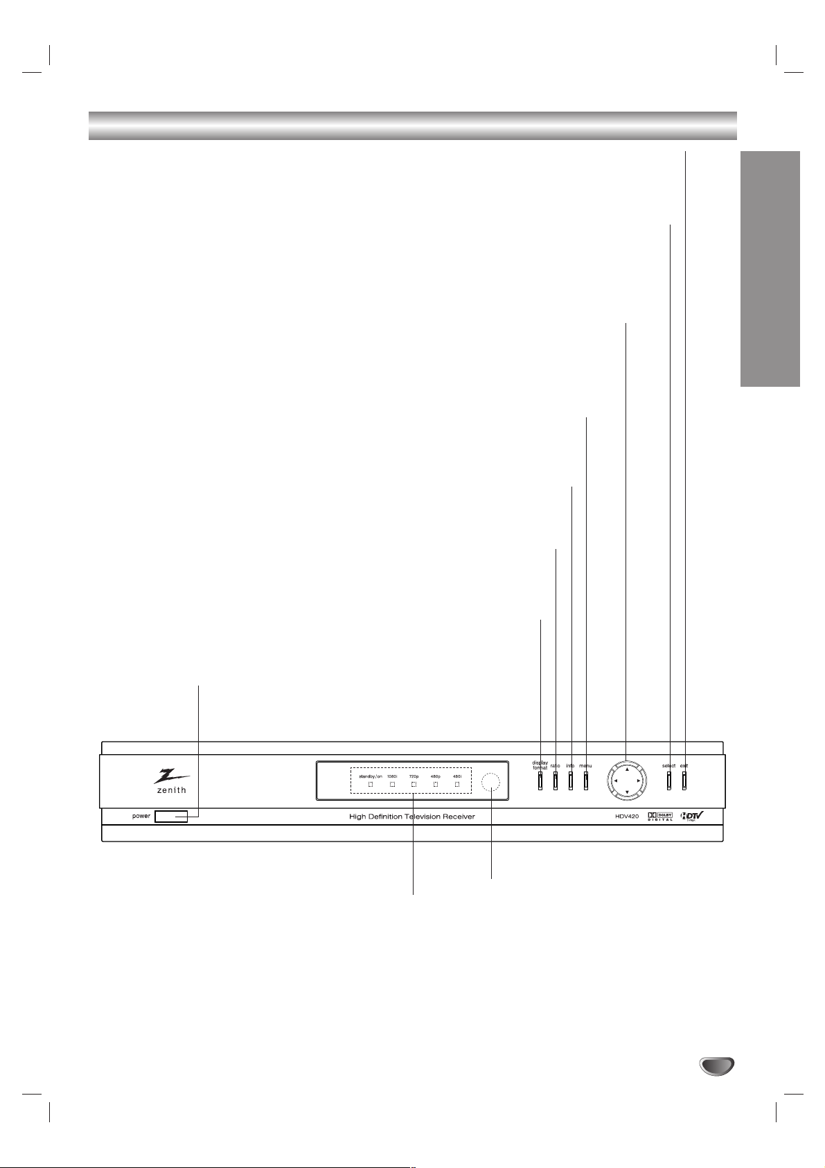
Front Panel
Remote Control Sensor
Receives signals from the remote control.
Status Indicators
Shows HDTV Receiver status: Current power, and
display output format.
EXIT
Clears all on-screen displays and returns
to normal viewing from any menu.
SELECT
If the main menu is displayed, pressing the Select button
will activate the selected MENU item. If the Select button
is pressed while you are in normal viewing, the information
banner will be displayed.
Arrow Buttons (
33
/
44
/
11
/
22
)
Allows you to navigate on-screen menus and to adjust the system settings and preferences.
Use the arrow keys to move to a menu option and then use the
SELECT
button to access it.
If no menu is displayed, the Left/Right arrows control the volume setting and the Up/Down
arrows select channels.
MENU
Shows the main menu on the screen. You can return to normal view-
ing by pressing the EXIT button.
INFO
Shows station and program information on the screen.
To remove the banner, press the button again.
RATIO
Changes the picture aspect ratio.
DISPLAY FORMAT
Sets the output resolution to one of 1080i, 720p, 480p, and 480i formats.
Choose the correct display format for your TV. (Refer to page 10-12)
Power
Turns the HDTV Receiver on or off.
6
Remote Control
Remote Control Operation Range
Point the remote control at the remote sensor and press
the buttons.
Distance: About 23 ft (7 m) from the front of the
remote sensor.
Angle: About 30° in each direction of the front of the
remote sensor.
Remote control battery installation
Detach the battery cover on the rear of the remote con-
trol, and insert two R03 (size AA) batteries with and
aligned correctly.
Caution
Do not mix old and new batteries. Never mix different
types of batteries (standard, alkaline, etc.).
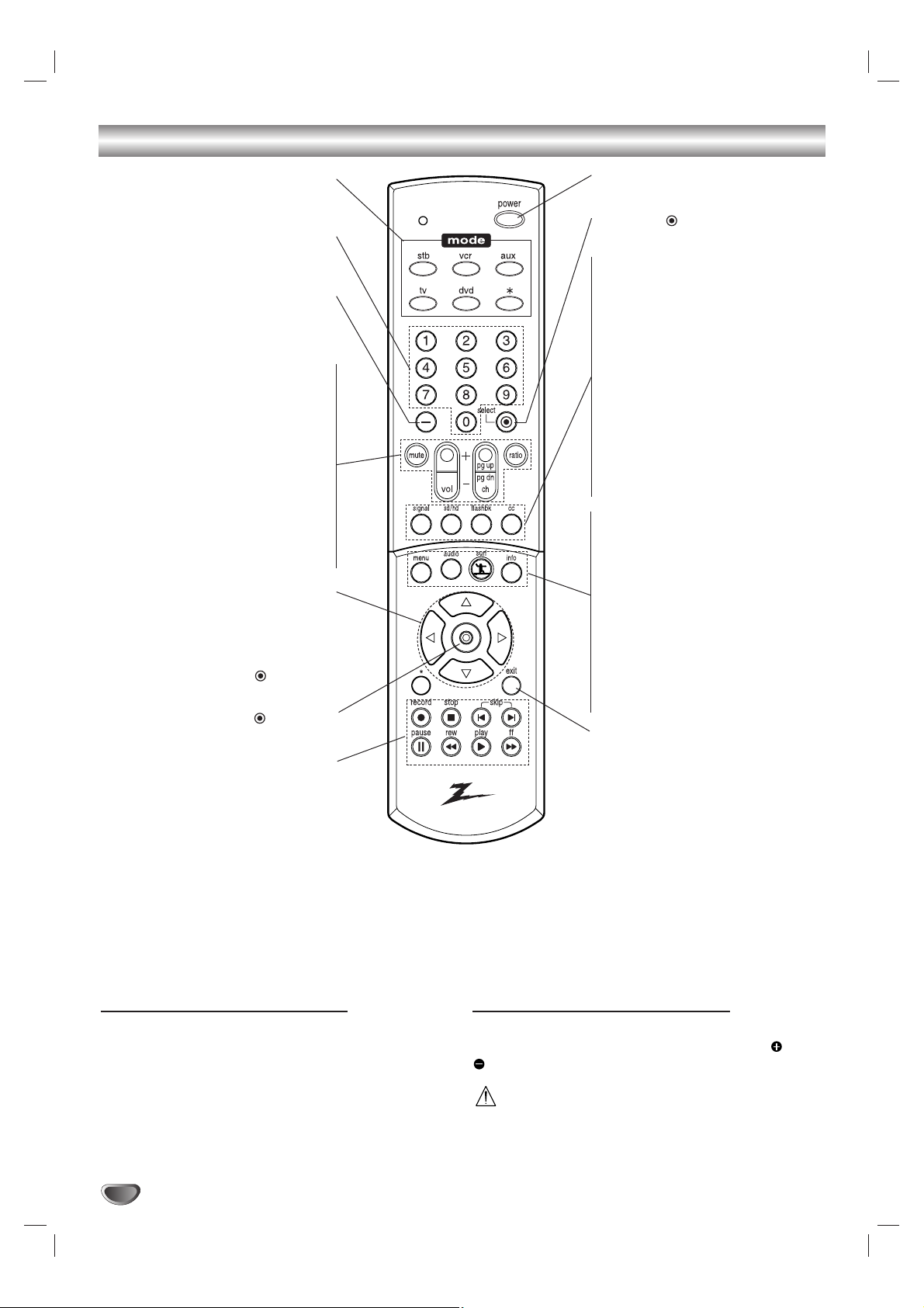
MODE
Selects operational mode of remote
control.
Numbers
Chooses channels and enters
programming information.
Dash (-)
Is used to enter a channel number
for multiple program channels such
as 2-1, 2-2, etc.
MUTE
Turns off TV sound. Press again to
restore TV sound.
VOL (Volume) (+/-)
Changes volume.
CH (Channel) (+/-), Page Up/Down
Selects a memorized channels or
scrolls the program list in the Guide
menu page by page.
RATIO
Changes the picture aspect ratio.
Arrow Buttons (
33
/
44
/
11
/
22
)
Allows you to navigate on-screen
menus and to adjust the system set-
tings and preferences. Use the arrow
keys to move to a menu option and
then use the (SELECT)
button to access it.
(SELECT)
Acknowledges menu selection.
Component Control Buttons
Provides control for DVD players,
VCRs, and similar components. The
SKIP buttons (. or >) are used
to jump chapter by chapter during
DVD playback. The remote control
must be programmed for the brand of
component being used. For further
instructions on remote control pro-
gramming, please refer to
pages 30-32.
POWER
Turns the HD Receiver ON and OFF.
SELECT ( )
Acknowledges menu selection.
SIGNAL
Shows the signal strength of the
current channel. You may improve the
signal strength by adjusting the
direction of your over-the-air antenna.
HD/SD
Sets the output resolution to one of
STD (480i format) and pre-selected
HD (480p, 720p, and 1080i).
FLASHBK
Returns to the last channel viewed.
CC
Turns closed caption on and off.
MENU
Accesses or closes main menu.
AUDIO
Selects an audio language of the
program (English, French, Spanish).
SURF
Selects the list of your surf chan-
nels.
INFO
Shows station and program infor-
mation on the screen.
EXIT
Removes all on-screen displays
and returns to TV viewing from any
menu.
7
INTRODUCTION
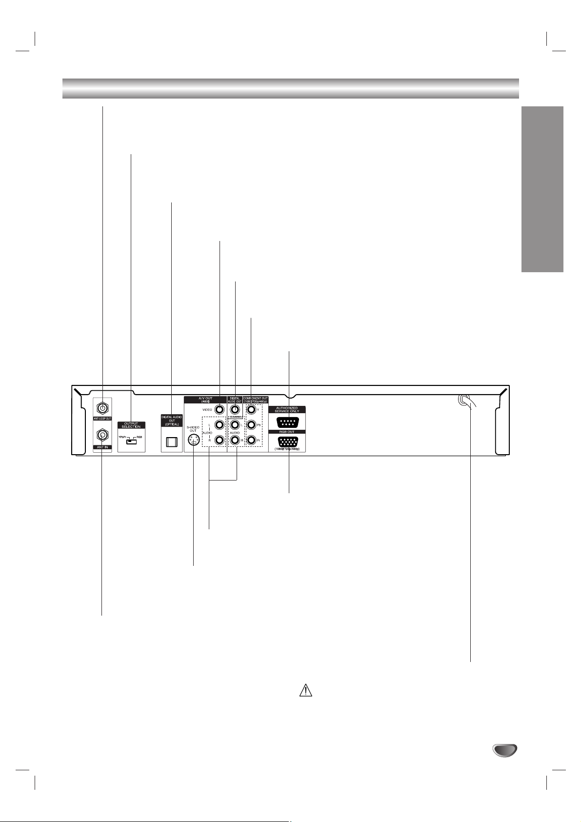
Rear Panel
Do not touch the inner pins of the jacks on the rear
panel. Electrostatic discharge may cause permanent
damage to the unit.
AC Power Cord
Plug into the power source.
ANT LOOP OUT
Connects to TV ANT IN jack. Provides an RF connection between the
HDTV Receiver and the TV. Provides the signal of ANT IN jack to TV.
OUTPUT SELECTION
Select either YPbPr or RGB depending on how you connect the HDTV Receiver
to the TV.
OPTICAL (Digital audio out jack)
Connect to digital (optical) audio equipment.
COAXIAL (Digital audio out jack)
Connect to digital (coaxial) audio equipment.
VIDEO OUT
Connect to a TV with video inputs.
YPbPr OUT
Connect to a TV with YPbPr inputs.
AUTHORIZED SERVICE ONLY
Is used only for authorized service purposes.
ANT IN
Use to receive HDTV signal from external/internal antenna
connected to the HDTV Tuner.
S-VIDEO OUT
Connect to a TV with S-Video inputs.
AUDIO OUT (Left/Right)
Connect to a TV, amplifier, receiver or stereo system.
RGB OUT
Connect to a TV with RGB inputs.
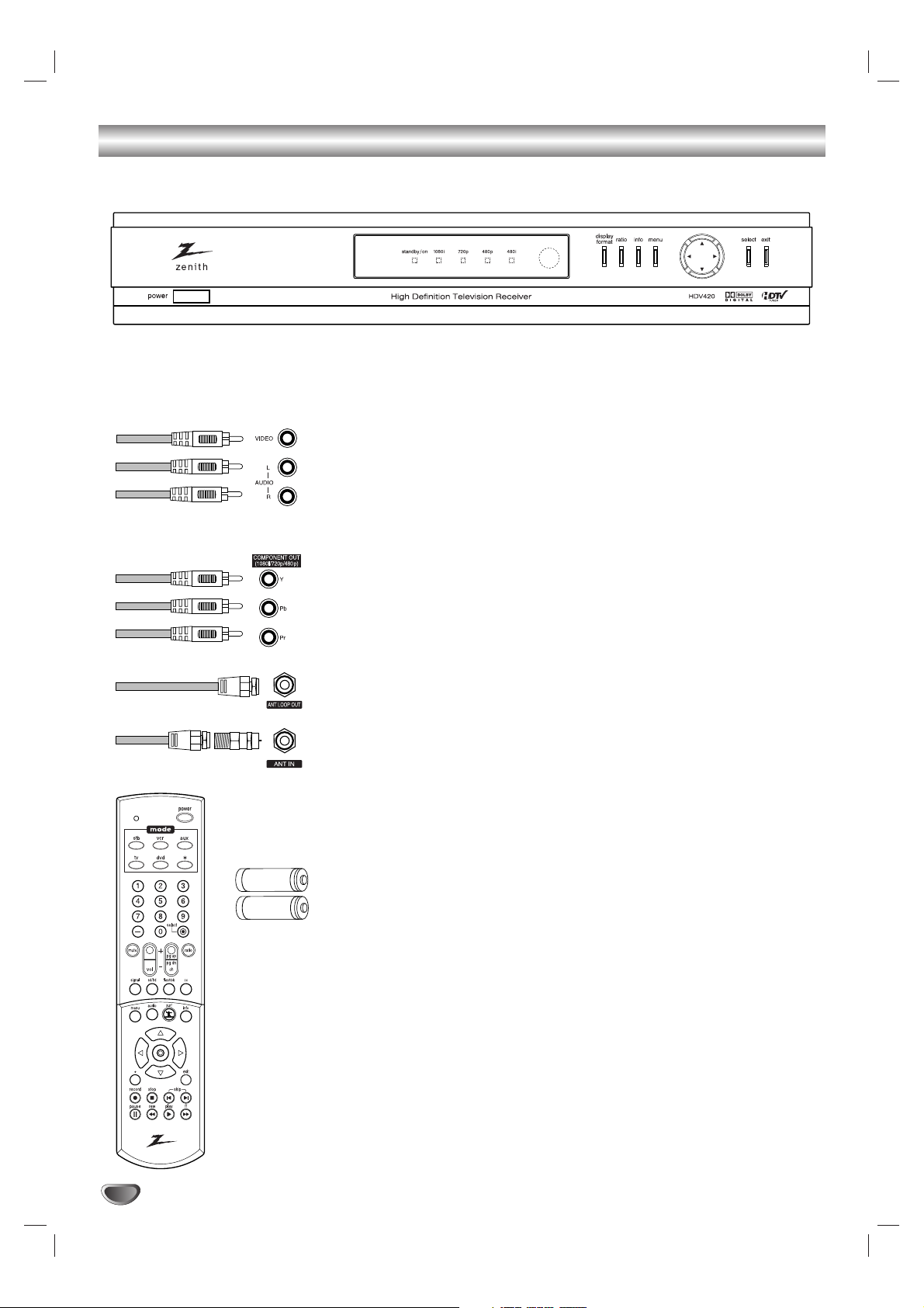
Unpacking
8
High Definition Television Receiver
The HDTV Receiver is capable of receiving signals from the cable, and/or
over-the-air antenna and sending the decoder signals to your TV.
Audio/Video Jacks and Cables
The Audio/Video jacks provide excellent picture and sound quality. They are
used for making most Audio/Video connections between components. The
Audio/Video jacks may be color coded (yellow for video, red for right audio,
and white for left audio). If your component has only one input for audio
(mono), connect it to the left (white L/mono) audio jack on the HDTV
Receiver.
Component Out Jacks and Cables
Component Cables are used to connect the HDTV Receiver to an industry
standard YPbPr compatible HD Monitor. Remember to connect the left and
right audio cables. A Component jack carries only the picture signals, not
the sound.
ANT LOOP OUT Jack, and RF Cable
ANT LOOP OUT provides an RF connection between the HDTV Receiver
and the TV and provides the signal of ANT IN jack to TV.
Attenuator
During initial installation and setup of your new Zenith HDTV Receiver, you
may need to install the 10 dB attenuator, to the Antenna input “ANT IN” ter-
minal on the HDV420. Details are on page 9.
Remote Control
In addition to the HDTV Receiver, the remote control can be programmed to
control many other devices.
Batteries
To install the batteries, slide open the battery compartment and insert the
two AA batteries provided.
Make sure you have received all these items listed below with the High Definition Television Receiver.
AA
AA
PREPARATION
9
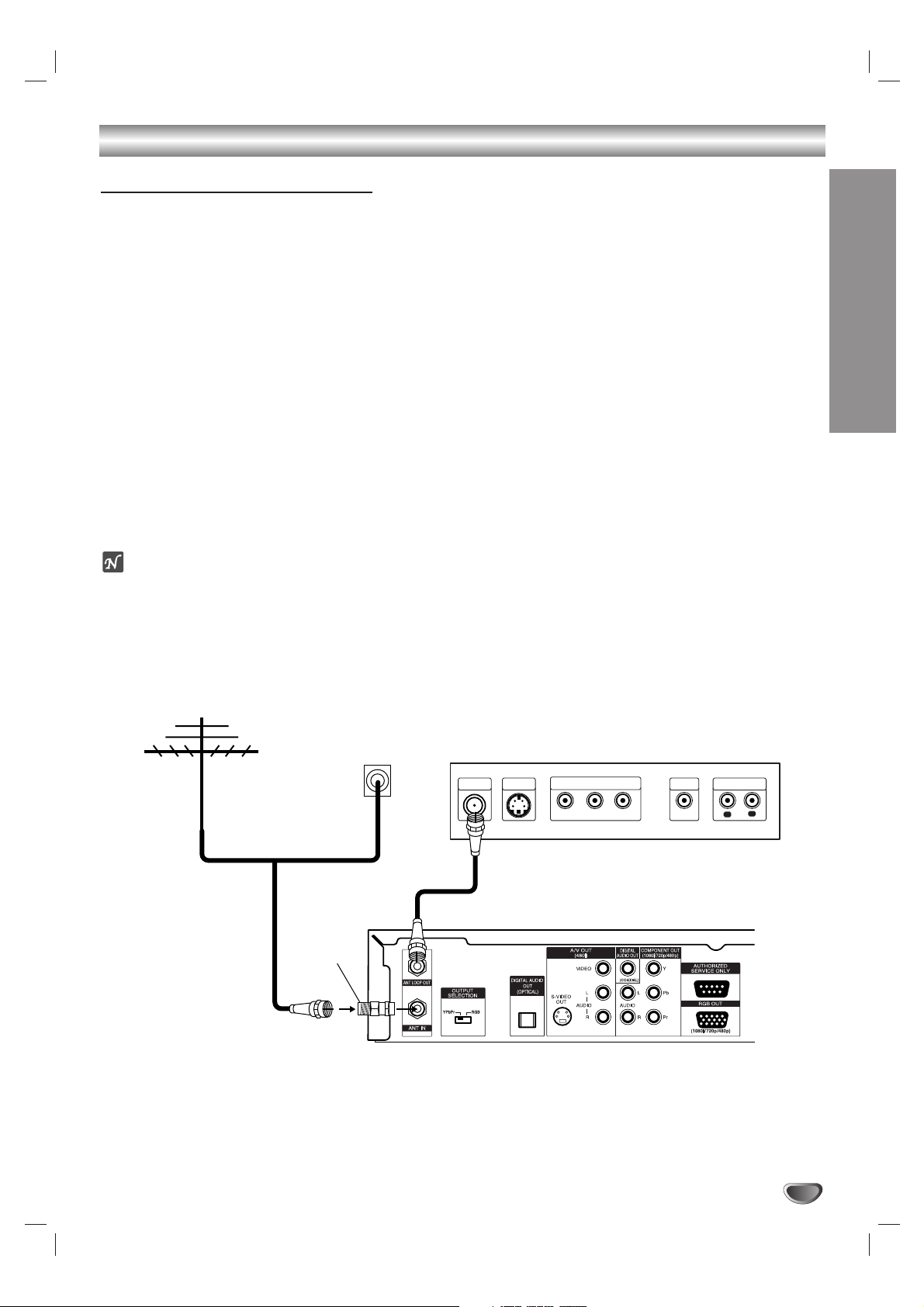
Connections
Connecting to an Antenna
Before connecting an antenna
Dear consumer purchaser of Zenith High Definition Television Receiver HDV420.
In addition to the components and accessories supplied with your Zenith HDTV Receiver, we have included a small
device called a “10 dB Attenuator”. During initial installation and setup of your Zenith HDTV Receiver, you may need
to install the 10 dB attenuator to the Antenna input “ANT IN” on the HDV420. The HDV420 is a high performance,
high gain system intended for operation under normal and weak signal conditions, providing the best reception with
its optimum gain. However, there might be some reception areas where the signal strength is too high (e.g. due to
close proximity to a undesirable signal or transmitter), so we included an attenuator that lowers the incoming signal
strength (from the undesirable transmitter) to more normal levels. This 10 dB attenuator should be used only in a
reception area where an undesired signal strength is too high. One of the possible symptoms would be that after
your program/channel search, your HDTV receiver does not find all the local digital terrestrial channels available in
your area. (You can find HDTV channels/content information for your local broadcast area by going to Zenith web-
site “WWW.ZENITH.COM” and clicking on “HDTV Program Schedule” under HDTV.) Please make sure that before
deciding to use the supplied attenuator device, you are using an appropriate and properly aligned UHF/VHF RF ter-
restrial antenna.
11
Connect the “Antenna” to the “ANT IN” jack on the HDTV Receiver using a coaxial RF cable.
ote
There might be some areas where the signal strength could is too high. If so, you may need to connect the antenna
to an attenuator and screw the attenuator onto the “ANT IN” jack.
22
Connect the “ANT LOOP OUT” jack on the HDTV Receiver to the “ANT IN” jack on your TV using a coaxial RF
cable.
Cable TV
wall jack
Attenuator
OR
L
R
Y
Pb
Pr
COMPONENT VIDEO INPUT
AUDIO INPUT
L
VIDEO
INPUT
S-VIDEO
INPUT
ANTENNA
INPUT
Rear of TV
Rear of HDTV Receiver
Antenna
Connections (Continued)
10
Display Formats Overview
The HDTV Tuner offers various display formats and multiple video outputs. When the HDTV Tuner is connected to
A/V systems, the HDTV Tuner can provide video signal formats 1080i, 720p, 480p, or 480i.
1080i, 720p and 480p modes are available for component video (YPbPr) and monitor outputs.
480i mode is available for VIDEO and S-VIDEO outputs.
The HDTV Tuner has two digital audio outputs; Dolby Digital 5.1 and PCM. The HDTV Tuner sends out digital audio
signal to OPTICAL and COAXIAL audio outputs when digital broadcastings are being received by the HDTV Tuner.
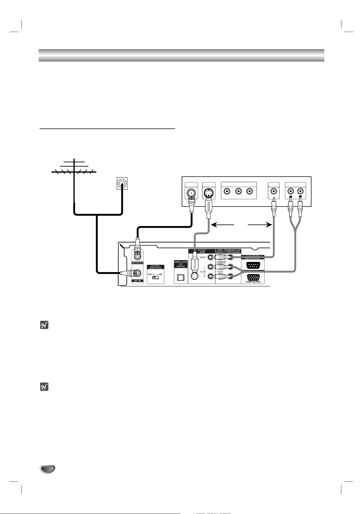
Connecting to an Analog monitor
11
Connect the “Antenna” to the “ANT IN” jack on the HDTV Receiver using a coaxial RF cable.
ote
There might be some areas where the signal strength could is too high. If so, you may need to connect the antenna
to an attenuator and screw the attenuator onto the “ANT IN” jack. (Refer to page 9.)
22
Connect the “ANT LOOP OUT” jack on the HDTV Receiver to the “ANT IN” jack on your TV using a coaxial RF
cable.
33
Connect the “AUDIO OUT” and “VIDEO OUT” jacks on the HDTV Receiver to the “A/V IN” jack on your TV
using RCA-type cables. If your VCR is equipped with an S-Video jack, use the S-VIDEO OUT jack.
ote
These connections are only available when 480i display format is selected.
Cable TV
wall jack
OR
OR
L
R
Y
Pb
Pr
COMPONENT VIDEO INPUT
AUDIO INPUT
L
VIDEO
INPUT
S-VIDEO
INPUT
ANTENNA
INPUT
Rear of TV
Rear of HDTV Receiver
Antenna
PREPARATION
11
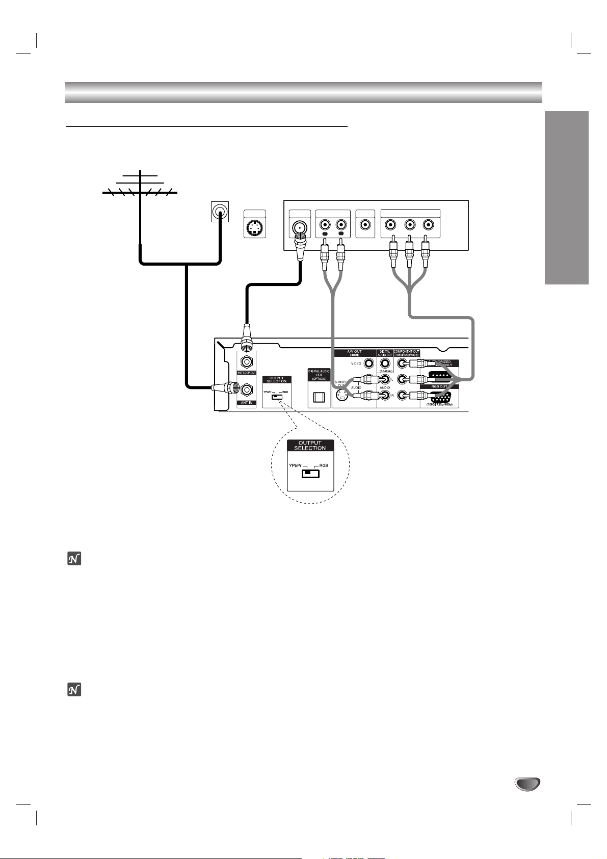
Connections (Continued)
Connecting to a HD monitor (YPbPr type)
11
Connect the “Antenna” to the “ANT IN” jack on the HDTV Receiver using a coaxial RF cable.
ote
There might be some areas where the signal strength could is too high. If so, you may need to connect the antenna
to an attenuator and screw the attenuator onto the “ANT IN” jack. (Refer to page 9.)
22
Connect the “ANT LOOP OUT” jack on the HDTV Receiver to the “ANT IN” jack on your TV using a coaxial RF
cable.
33
Connect the “COMPONENT OUT” jacks on the HDTV Receiver to the “COMPONENT IN” jacks of your TV
using RCA-type cables. (The OUTPUT SELECTION switch must be set to YPbPr.)
44
Connect the L/R “AUDIO OUT” jacks on the HDTV Receiver to the L/R “AUDIO IN” jacks on your TV using
RCA-type cables.
ote
The component out jacks are available when 480p, 720p, or 1080i display format is selected.
Cable TV
wall jack
OR
L
R
Y
Pb
Pr
COMPONENT VIDEO INPUT
AUDIO INPUT
L
VIDEO
INPUT
S-VIDEO
INPUT
ANTENNA
INPUT
Rear of HD Ready TV
Rear of HDTV Receiver
Antenna
 Loading...