


PV-4660
Zenith PV-4660, PV4663BT, PV5263RK7, PV4663HK, PV5264RK Operating Manual & Warranty
...
THE QUALITY GOES IN BEFORE TI--IENAME GOES ON®
iAviso para nuestros
clientes de habla hispana:
consulte la informaci6n que
aparece al final de este manual!
Projection Color TV •
MTS Stereo Audio"
Surround Sound
Closed Captions
recycled paper
50 percent
Return the Product Registration
Card, and your TV could be free!
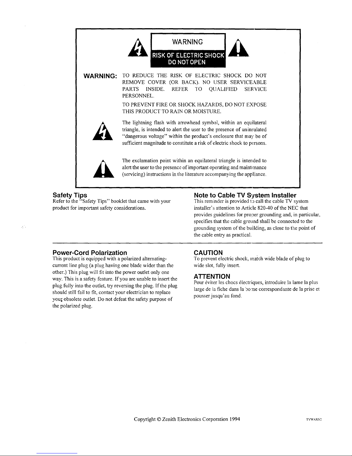
WARNING:
TO REDUCE THE RISK OF ELECTRIC SHOCK DO NOT
REMOVE COVER (OR BACK). NO USER SERVICEABLE
PARTS INSIDE. REFER TO QUALIFIED SERVICE
PERSONNEL.
TO PREVENT FIRE OR SHOCK HAZARDS, DO NOT FXPOSE
THIS PRODUCT TO RAIN OR MOISTURE.
The lighming flash with arrowhead symbol, within an ecluilateral
triangle, is intended to alert the user to the presence of uninsulated
"dangerous voltage" within the product's enclosure that may be of
sufficient magnitude to constitute a risk of electric shock to persons.
_]k The exclamation point within an equilateral triangle is intended to
alert the user to the presence of important operating and maintenance
(servicing) instructions in the literature accornpanying the appliance.
Safety Tips
Refer to the "Safety Tips" booklet that came with your
product for important safety considerations.
Note to Cable TV S,tstem Installer
This reminder is provided t_ call the cable TV system
installer's attention to Article 820-40 of the NEC that
provides guidelines for prol_ergrounding and, in particular,
specifies that the cable gJ'onnd shall be connected to the
grounding system of the building, as close to the point of
the cable entry as practical.
Power-Cord Polarization
This product is equipped with a polarized alternating-
current line plug (a plug having one blade wider than the
other.) This plug will fit into the power outlet only one
way. This is a safety feature. If you are unable to insert the
plug fully into the outlet, try reversing the plug. If the plug
should still fai! to fit, contact your electrician to replace
you!; obsolete outlet. Do not defeat the safety purpose of
the polarized plug.
CAUTION
To prevent electric shock, match wide blade of plug to
wide slot, fully insert.
ATTENTION
Pour _viter les chocs dlectriques, introduire la lame la plus
large de la fiche dans la iao:ne correspondante de la prise et
pousser jusqu'au fond.
Copyright © Zenith Electronics Corporation 1994 rVWAm,'2
CONTENTS
INTRODUCTION
'Welcome ......................................... ii
][nstallation Considerations ........................... ii
CONNECTIONS FOR YOUR TV
]Locations of User Items ............................. I- 1
Connection Center on Back of TV .................... 1-2
Other AiV Jacks on TV ............................. 1-2
Step 1. Make Basic Connection to TV ................. 1-3
Step 2. Make VCR Connections to TV ................. 1-4
Step 3. Make Super-VHS VCR Connections to TV ....... I-5
Step 4. Make A/V Connections to Auxiliary
A/V Jacks (VIDEO 3 IN or S-VIDEO 2 IN) .......... I-5
Step 5. Make Connections to Monitor Out Jacks ......... 1-5
Step 6. Make Surround Sound Connections to TV ........ 1-6
Step 7. Make External Speaker Connections to TV ....... 1-6
Step 8. Make Audio Connection to Stereo Amplifier ...... 1-7
THE FIRST TIME YOU OPERATE YOUR TV
Step 1. Connect the Power ........................... 2-1
Step 2. Select Your Viewing Source ................... 2-1
Step 3. Use Auto Program ........................... 2-1
Step 4. Time Functions ............................. 2-1
Step 5. Use Other Options ........................... 2-2
REMOTE CONTROL MODEL SC3820
"FV Operations .................................... 3-1
VCR Operations .................................. 3-2
TV and VCR Operational Notes ...................... 3-3
Preparation for Use ................................ 3-3
Installing Batteries ................................. 3-3
REMOTE CONTROL MODEL MBR3430
Operation ........................................ 4-1
Choose the Operating Mode ......................... 4-1
TV Operations .................................... 4-2
VCR Operations .................................. 4-3
Cable-TV Operations ............................... 4-4
Preparation for Use ................................ 4-5
Installing Batteries ................................. 4-5
Programming Brand Codes .......................... 4-6
TV, VCR and Cable-TV Operating Codes .............. 4-7
QUICK REFERENCE TO ON-SCREEN MENUS
Available Menus .................................. 5-1
Summary of Menu Items ............................ 5-1
Menu Operation Example ........................... 5-3
SOURCE MENU
Source Selection .................................. 6-1
Source Identification ............................... 6-1
SETUP MENU
Auto Program .................................... 7-1
Ch. Add/Del ....................................... 7-1
Ch. Labels ....................................... 7-2
Tuning Band ..................................... 7-3
Auto Tuning ...................................... 7-3
Source ID ........................................ 7-3
Clock Set ......................................... 7-4
CaptiOns .......................................... 7-4
Projo Setup ....................................... 7-5
AUDIO MENU
Bass ............................................. 8-1
Treble ............................................ 8-1
Balance .......................................... 8-1
Audio ............................................ 8-1
SEQ ............................................. 8-1
Surround ......................................... 8-1
VIDEO MENU
Contrast .......................................... 9-1
Brightness ........................................ 9-1
Color ........................................... 9-1
Tint ............................................. 9-1
Sharpness ........................................ 9-1
Color Temp ...................................... 9-1
Video Filter ...................................... 9-1
Auto Flesh ....................................... 9-1
Picture Pref ...................................... 9-I
PIP MENU
Ch. Guide ....................................... 10-1
Ch. Review ..................................... 10-2
PIP Source ...................................... 10-2
PIP Color ...................................... 10-3
PIP Tint ......................................... 10-3
PIP Size ....................................... 10-3
PIP OPERATION AND COI_NECTIONS
PIP Overview ..................................... 11-I
Typical Connections ............................... 11-1
How to Select Main Picture & PIP Source ............. 1 I-3
PIP Functions ................................... 11-4
MAINTENANCE AND TRO1LJBLESHOOTING
Caring for Your TV ................................ 12-1
Extended Absence ................................ 12-1
TV Picture Interference ............................ 12-I
Before Calling for Service .......................... 12-2
Product Registration Card
Recommended Accessories For Your TelevMon
Aviso para nuestros clientes de habla hispanLa
Your Zenith Warranty
HOW TO USE YOUR OPERATING GUIDE
THIS OPERATING GUIDE DESCRIBES A FAMILY OF TV MODELS. SOME MODELS tIAVE FEATURES THAT ARE
NOT PROVIDED ON OTHER MODELS, SUCH AS AUXILIARY JACKS OR TWO REMOTE CONTROLS. DIFFERENT
CONTROL PANELS AND REMOTE CONTROLS MAY BE USED FROM MODEL-TO-MODEL. REFER TO THE APPLI-
CABLE SECTIONS OF THIS OPERATING GUIDE FOR THE FEATURES AND ITEMS PROV [DED WITH YOUR TV.
,n*-o i
INTRODUCTION
WELCOME
Welcome into the family of Zenith Color Television owners.
This guide provides instructions on how to operate your new
TV. It is supplemented by a booklet containing Safety Tips.
We urge you to read these publications carefully so that you
will receive full enjoyment from your new Zenith TV for
many years to come.
Your new Zenith projection TV has been designed and built to
give you the very best in quality, features and performance.
There are many regional Zenith distributors and thousands of
distributor-approved Zenith service centers throughout the
U.S., Canada and Mexico who can attend promptly and effec-
tively to ordinary service needs.
If you should have an unusual performance or service problem
that cannot be satisfactorily resolved by your distributor-
approved Zenith service center, contact the regional Zenith dis-
tributor in your area, or write:
Zenith Electronics Corporation
Customer Servi,:zeDepartment
1000 Milwaukee Avenue
Glenview, IL 6(1625-2493
Telephone: (847) 391-8752
Mon-Fri, 8:00 a.m. - 4:30 p.m. Central Time
Send the model number, serial number, and date of purchase
or original installation, with a full explanation of the problem
and the service history. We will welcome,,the opportunity to
look into your specific question or problem and to be of assis-
tance in resolving it promptly.
The model and serial numbers of your new TV are located on the
back of the TV cabinet. For your future convenience and protec-
tion, we suggest that you recorJ these numbers here:
Model No.
Serial No.
INSTALLATION CONSIDERATIONS
Before you install your TV...
Ventilation -- Proper ventilation keeps your TV
running cool. Air circulates through perforations
in the back and bottom of the cabinet. Do not
block these vents or you will shorten the life of
your TV.
_.iPower Source Your TV is designed to
operate
u
on normal household current, 120 volt 60 Hertz AC.
Do not attempt to operate it on DC current.
Power Cord -- Your power cord has a polarized
plug as required by Underwriters' Laboratories. It
has one regular blade and one wide blade and fits
only one way into a standard electrical outlet. If
the blades will not enter either way, your outlet is
very old and non-standard. A new outlet should be
installed by a qualified electrician.
Safe Operation -- Your TV is manufactured and
tested with your safety in mind. However, unusual
stress caused by dropping or mishandling, expo-
sure to flood, fire, rain or moisture, or accidental
spilling of liquids into the TV, can result in poten-
tial electrical shock or fire hazards. If this hap-
pens, have your TV checked by a service
technicmn before using it again.
Please read and observe each safety point in the "Safety
Tips" folder when installing and using your TV.
VIDEO GAMES AND OTIIER FIXED
PATTERN DISPLAY CAUTION -- I5you use your TV for
video games, teletext or othm fixed displays, avoid setting the
BRIGHTNESS control for at, excessively bright picture. A
bright, fixed pattern, if used for long periods of time, can re-
sult in a permanent imprint on the TV picture tube. You can re-
duce this possibility by alternating the use of the fixed pattern
display with normal TV picture viewing, by turning down the
CONTRAST control for sustained fixed pattern use, and by
turning oft the fixed pattern display when nol in use.
PLUGGING IN YOUR 'rv -- Be sure to plug your TV into
an "unswitched" AC power source. The "switched" AC out-
lets found on some video ,equipment will not continue supply-
ing power to the TV once the equipment is turned off. If the
power to the TV is interrupted, you will have to reset the clock
in the TV to the current time.
PICTURE SCREEN CLEANING -- Use a soft cloth mois-
tened with warm water and rub lightly in the soiled areas of
the screen. DO NOT USE A FISSUE OP, PAPER TOWEL,
AS THESE MAY DAMAGE SURFACE. Wipe only in the
vertical (up/down) direction (along the grooves). If there is a
dirt buildup, a mild solution of warm wa:er and Ivory dish-
washing detergent may be:used. Use dr), soft cloth to dry the
screen. Care should be taken to avoid scratches or damage to
the screen surface.
NOTE -- The TV screen is easily damaged. Avoid acciden-
tal contact with the screen.
TVWEPRO3 ii
CONNECTIONS FOR YOUR TV
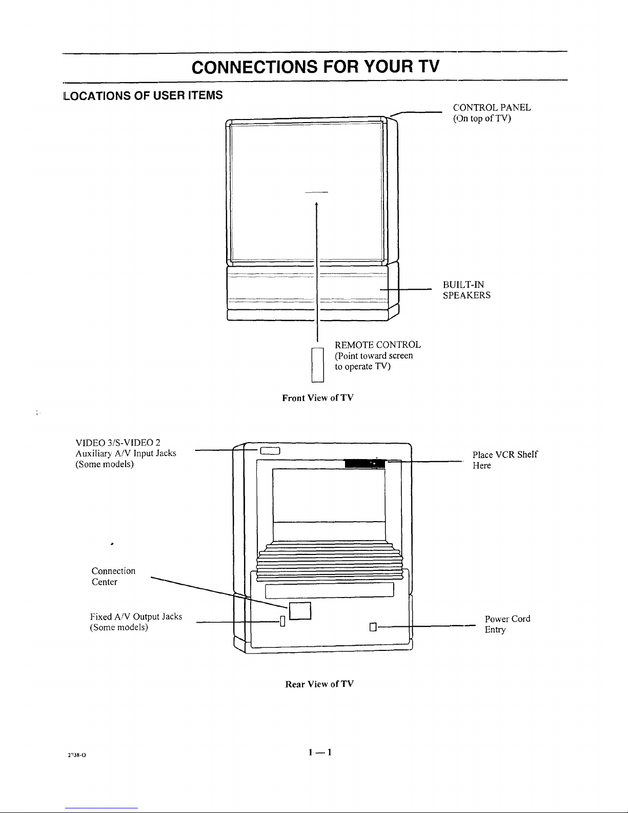
LOCATIONS OF USER ITEMS
f
I
REMOTE CONTROL
(Point toward screen
to operate TV)
Front View of TV
CONTROL ]?ANEL
(On top ofT'V)
BUILT-IN
SPEAKERS
VIDEO 3/S-VIDEO 2
Auxiliary A/V Input Jacks
(Some models)
Connection
Center
Fixed A/V Output Jacks
(Some models) []
Place VCR Shelf
Here
Power Cord
Entry
Rear View of TV
r,3s-o 1 _ 1
CONNECTIONS FOR YOUR TV
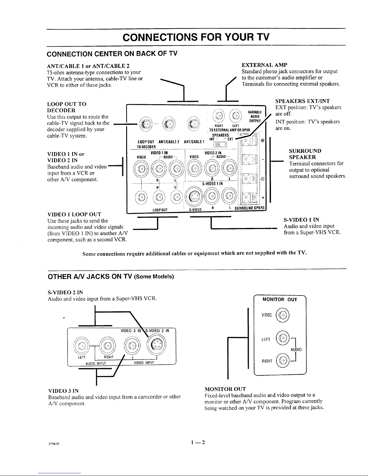
CONNECTION CENTER ON BACK OF TV
ANT/CABLE 1 or ANT/CABLE 2
75-ohm antenna-type connections to your
TV. Attach your antenna, cable-TV line or
VCR to either of these jacks.
LOOP OUT TO
DECODER
Use this output to route the
cable-TV signal back:to the
decoder supplied by :your
cable-TV system.
I
VIDEO 1 IN or
VIDEO 2 IN l
Baseband audio and video
--1
input from a VCR or
other A/V component.
VIDEO 1 LOOP OUT
Use these jacks to send the
incoming audio and 'video signals
(from VIDEO 1 IN) to another A/V
component, such as a second VCR.
LOOPOUT ANT/CABLE2
TODECODER
VIDEO1 IN
VIDEO r_AUDIO_
RI LI
LOOP OUT
A[qT/CABLE1 _]
VIDEO2 IN
VIDEO r- AUDIO
EXTERNAl, AMP
Standard phoao jack cormectors for output
to the customer's audio amplifier or
Terminals for connecting: external speakers.
,/_,.S._, VARIABLE_i'ic 1
,_, AUDIO
OUTPUT
RIGHT LEFT
TOEXTERNALAMPORSPKR
SPEAKERS
INT _ [- EXT
R L
S-VIDEO1 IN
L SURROUNDSPKRS
!
S-VIOEO R
!
SPEAKERS EXT/INT
EXT position: TV's speakers
are off.
INT position: TV's speakers
are on.
SUIGROUND
SPEAKER
Terminal connectors for
output to optional
surround sound speakers.
S-VIDEO 1 IN
Audio and video input
from a Super-VHS VCR.
Some connections require additional cables or equipment which are not supplied with the TV.
OTHER A/V JACKS ON TV (Some Models)
S-VIDEO 2 IN
Audio and video input from a Super-VHS VCR.
I VIDEO 3I_N S-VIDEO 2 IN
, -
AUDIO INPUT VIDEO INPUT
MONITOR OUT
AUDIO
VIDEO 3 IN
Baseband audio and video input from a camcorder or other
A/V component.
MONITOR OUT
Fixed-level baseband audio arid video output 1:0 a
monitor or other A/V component. Program currently
being watched on your TV is provided at these jacks.
2738-o 1 -- 2
CONNECTIONS FOR YOUR TV
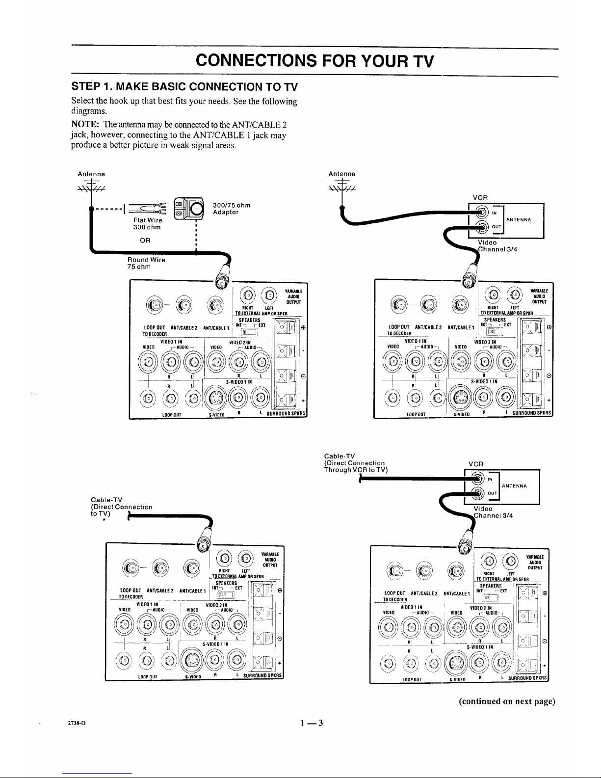
STEP 1. MAKE BASIC CONNECTION TO TV
Select the hook up that best fits your needs. See the following
diagrams.
NOTE: The antenna may be connected to the ANT/CABLE 2
jack, however, connecting to the ANT/CABLE 1jack may
produce a better picture in weak signal areas.
Antenna
...... I__ _
Flat Wire
300 ohm
,,
OR
|
i
Round Wire
75 ohm
300/75 ohm
Adaptor
J
_--_ _ VARIABLE
AUOlO
OUTPb'T
RIGHT LEFT
TO EXTERNAl_AMP ORgPKR
SPEAKERS
L00P0uTA.t/cAsLE2AWTIcxsLel'_mtr_eXT Il'o'll!Nle
viDeo1IN video2iN / !
VIDEO r--AUDIO_ VIDEO ;- AUOlO-_ I I r_ I_Tl
' L,%_!'"
LOOP OUT S-VIDEO R L SURROUND SPI(RS
Antenna
VCR
t __'=-'__b '7"1ANtE"N'I
I ,"_k outl I
Ghannel 3/4
_-',_ :x, vAR_,_
r_o ] ( {I o I I AUOlO
_ _ [ TO EXTERIqAL AMp ORSPIR
LQOPOUTANT/CABLE2lUtt/cXetE1im_/_ exT II'o'l II I_
TOUE_OOER__ ___ I _,. i,_tI
VIDEO1in vineo2m i ! i I
YiOE0 mAUDIO-1 VIDEO r--AOel[I-_ II_ll.
/ R LI _r___ L_i I.o. I1'_1®
--_ -_ -- _ S-VIDEO1 IN I _
LOOPOUT S-VIQEO B t SURROUNO SPIll
Cable-TV
(Direct Connection
toTV)•
Cable-TV
(Direct Connection
Through VCR to TV)
VCR
I 'q ANTENNA
I
Video
3/4
LOOP OUT ANT/CA61_E2 ANT/CABLE 1
TODECQDER
VIDEOllN VIDEO21N
VIDEO -AUOlO_ i VIDEO r- AUDIO-q
i AUDIO
OUTPUT
RIGHT LEFT
TOEI[TERNAI. lIMP OR IPKR
SPEAKER!I
iNT"'1 r EXT
LOOPOUI S-VIDEO L SURROUND SPKRS
(continued on next page)
2Tas-o 1-- 3
CONNECTIONS FOR YOUR TV
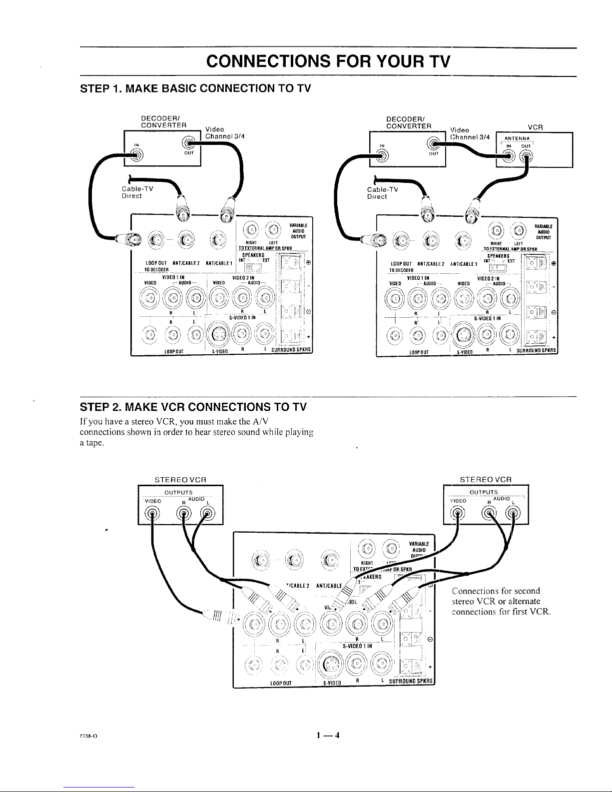
STEP 1. MAKE; BASIC CONNECTION TO TV
LOOPOUT
L SURROUND SPKRS
Cable-TV
Direct
I
DECODER/
CONVERTER "1 Video t VCR
._-_ / Channel 3/4 I ANTENNA
'" r-i_'
'i_Sa';', ,'_" / 7 =o,o
OUTPI/T
i_ ' TO E[IERI4AL.IMP ORSPill
SPEAKERS
LQOPOUT AHT/CABLI!2 J'_NT/CADLE1 INT_ r E),'T
TODECOOER _
VIDEO 1 IN VIOEO 2 !IN
VIDEO r AUDIO _ VIDEO _AUDIO_
LOOPOUT S-VIDEO
STEP 2. MAKE VCR CONNECTIONS TO TV
If'you have a stereo VCR, you must make the A/V
connections shown in order to hear stereo sound while playing
a tape.
STEREO VCR
OUTPUTS
VIDEO R AUDIO L
STEREO VCR
OUTPUTS
3_05_o
\'IDEO R L
I
' R Li
R LI
LOOPOUT
ANT/CABLE.
/
q
VluL;,
RIGH'[
S-VIDEO 1 IN
i,
C i ili
S-VIDEO R L SU£BOUNDSPKR
Connections for second
stereo VCR or alternate
connections for first VCR.
?738-0 l --4
CONNECTIONS FOR YOUR TV
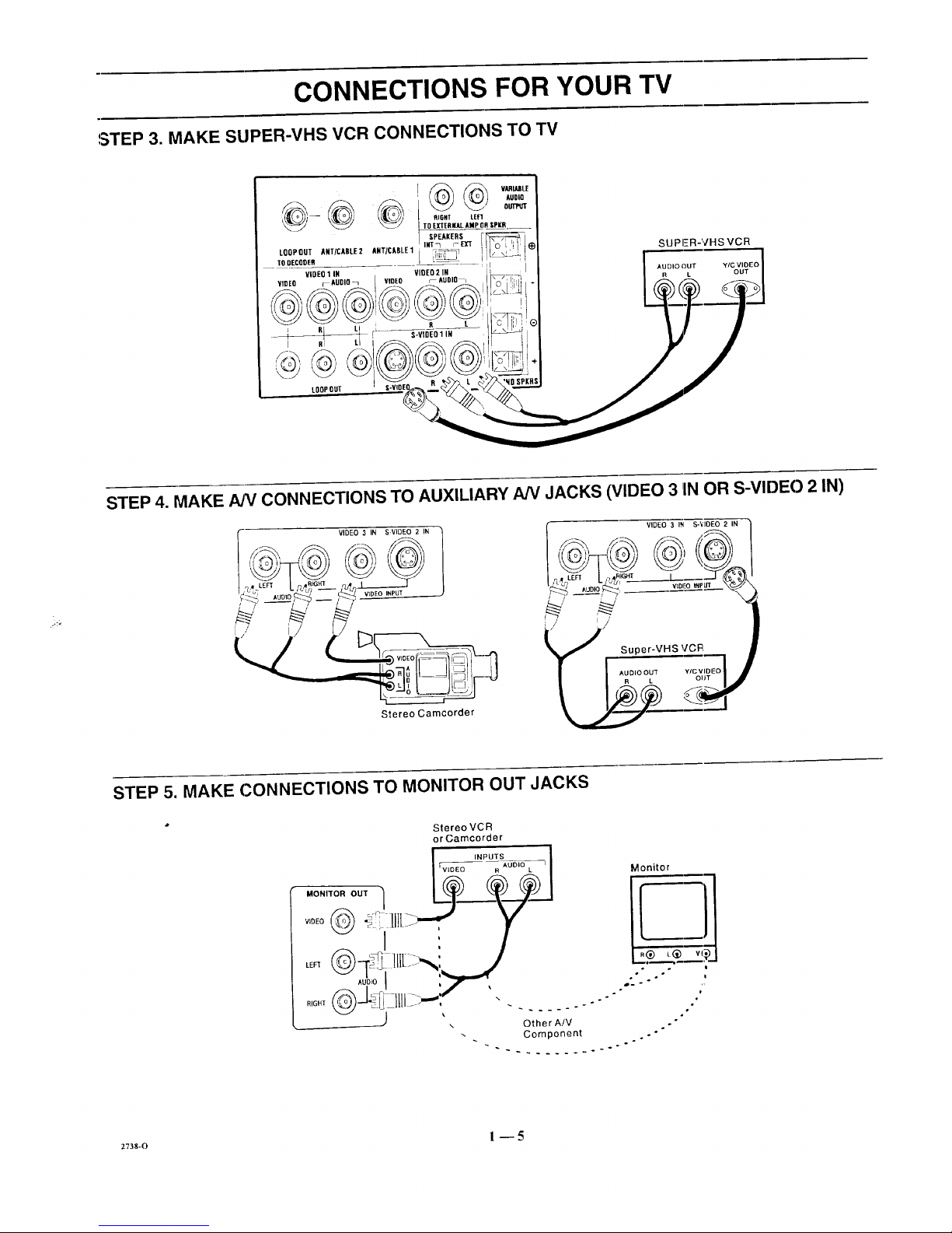
STEP 3. MAKE SUPER-VHS VCR CONNECTIONS TO TV
SUPER-VHS VCR
STEP 4. MAKE NV CONNECTIONS TO AUXILIARY NV JACKS (VIDEO 3 1INOR S-VIDEO 2 IN)
Stereo Camcorder
VIDEO 3 IN S-'¢IOEO 2 IN
.../' Super-VHS V'CFI
STEP 5. MAKE CONNECTIONS TO MONITOR OUT JACKS
StereoVCR
or Camcorder
INPUTS
Wr_EeOEe _uo_o L 7 Monitor
_1 . / -,
,oD,oI ,,_,-,,r
RIGHT _-J___ !_ Jill jm,-, . .... .. "
2738-0 1 _5

CONNECTIONS FOR YOUR TV
STEP 6. MAKE SURROUND SOUND CONNECTIONS TO TV
1. Mount and connect the optional surround sound
speakers by following the instructions provided with
the speakers.
2. Use the SURROUND option in the AUDIO Menu to
adjust the volume of the surround speakers.
,
The level of the surround sound varies relative to the
difference between the left- and right-channel stereo
signals.
NOTE: MAKE SUFIE 7V IS OFF
WHILE ,CONNECTING :SPEAKERS.
i AUD_
_ _ T_O EXTEflZ_r. AIIp O_ SPtA
I SPEAIERS [-P::_:_::::_:::_::;(7
LOOPOUT_rX_tEZ A,T_JUlt.E1i nrrr_ m" ILK;":,:",:,.
rD.c00,, __ t _ I1_ I_1
¥iDEOIIN I mEOZ" Eli___II I
HOED r-igoIo_ VIDEO r- AUDIO_ J I I\_/] _ [ " I
I
LOOPOUT S-VIDEO SURR RSI
Surround
Speaker
(8 ohm}
Surround
Speaker
(8 ohm)
STEP 7. MAKE EXTERNAL SPEAKER CONNECTIONS TO TV
1. Place the SPEAKERS EXT/INT switch on the TV in 3. Place the SPEAKERS EXT/INT switch on the TV in
the INT position, the EXT position.
2. Connect the two external speaker terminals.
NOTE: MAKE SURE TV IS OFF
WHILE CONNECTING SPEAKERS.
@@@
SPEAKERS
LOOP OUT ANTiCASII:2 ANT/CABLE1 INT7 r- E]rT
TO DECODER
VIDEO 1 IN VIDEO 2 IN
VIDEO ;_AUDIO_ VIDEO r_ AUDIO_
At ti R I.
.!
LOOPOUT
TOEXTERNAl. AMP ORSrKR
S'VIOE01 IN _ (_
\ .,"
@#®
I(RSI-VIDE0 SURR U
Right
Speaker
(8 ohm)
Left
Speaker
{8 ohm)
+73s-o 1 --6
CONNECTIONS FOR YOUR TV
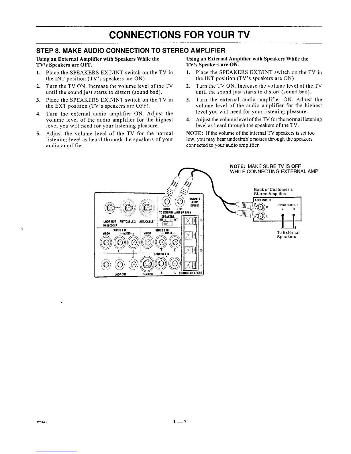
',STEP 8. MAKE AUDIO CONNECTION TO STEREO AMPLIFIER
Using an External Amplifier with Speakers While the
TV's Speakers are OFF'.
I. Place the SPEAKERS EXT/INT switch on the TV in
the INT position (TV's speakers are ON).
2. Turn the TV ON. Increase the volume level of the TV
until the sound just starts to distort (sound bad).
3. Place the SPEAKERS EXT/INT switch on the TV in
the EXT position (TV's speakers are OFF).
,4. Turn the external audio amplifier ON. Adjust the
volume level of the audio amplifier for the highest
level you will need for your listening pleasure.
5. Adjust the volume level of the TV for the normal
listening level as heard through the speakers of your
audio amplifier.
Using an External Amplifier with Speakers; While the
TV's Speakers are ON.
1. Place the SPEAKERS EXT/INT switch on the TV in
the INT position (TV's speakers are ON).
2. Turn the TV ON. Increase :the volume+ level of the TV
until the sound just starts to distort (_;ound bad).
3. Turn the external audio amplifier ON. Adjust the
volume level of the audio amplifier for the highest
level you will need for your listening pleasure.
4. Adjust the volume level of the TV for the normal listening
level as heard through the speakers of the TV.
NOTE: If the volume of the internal TV speaker; is set too
low, you may hear undesirable noises througl_Lthe speakers
connected to your audio amplifier
NOTE: MAKE SURE "IV IS OFF
WHILE CONNECTING EXTERNAL AMP.
.......@ + +
::: :' : TO EXTERNAL AMP OR SPI(R
SPEAKERS
F_
ToLOOPDEcODEROUTANT/CABLE2 ANT/CABL£1 INT_i- EX'T
VIOEO1 IN VIDEO2 iN
@_@__@_VlO[O F- AUDIO-1 VIDEO r- AUDIO_L _iO
RI I R
,I LL S-V|DEO 1 IN
LOOPOUT S-¥1DEO R
_ VARiAJIL£
AUDIO
OUTPUT
÷
L SURROUHOSPKRS
Back of Customer's
Stereo Amplifier
'+++]lij
SPKR OUTPUT
L R
L,. _-=j
To External
Speakers
:z73s-o 1 -- 7

THE FIRST TIME YOU OPERATE YOUR TV
STEP 1. CONNECT THE POWER
A. Plug: your TV into an unswitched AC power source.
B. Turn the TV ON by pressing OFF-ON.
!
Do not plug TV into switched outlet
on cable-TV decoder or VCR
STEP 2. SELECT YOUR VIEWING SOURCE
A TV source refers to the equipment connected to the TV that
supplies the picture and sound to your "IV. You select the
viewing source by using the SOURCE MENU.
NOTE: The antenna or cable must be connected to the TV
before using AUTO PROGRAM to find available channels.
To Access SOURCE MENU
1. Press SOURCE on the remote control to view the
SOURCE MENU.
2. Press SOURCE repeatedly until the desired source is
highlighted.
3. Press ENTER to return to normal viewing.
c;DUREE
* Some models only.
[ANT/CABLE "1
ANT/CABLE 2
VIDEO 1
VIDEO 2
S-VIDEO 1
VIDEO 3 -_,_
S-VIDEO 2 -x'-
STEP 3. USE AUTO PROGRAM
AUTO PROGRAM finds all available channels and stores
them in the memory of the TV for use by CHANNEL (CH)
Up/Down. Use AUTO PROGRAM only when you first
install your TV, or when you permanently change the
connections to the "FV. For example, when you replace the
antenna with a cable--TV system.
NOTE: AUTO PROGRAM can only be used with ANT/
CABLE 1 or 2 Source selection.
To Use AUTO PROGRAM
1. Press MENU on your remote control repeatedly until
the SETUP MENU appears.
2. Press SELECT (SEL) UP/DOWN to highlight Auto
Program.
3. Press ADJUST (ADJ) Left/Right to start Auto Program.
4. Use AUTO PROGRAM independently for each AN-
TE.NNA or CABLE signal source connected to your
TV. Select one source by using the SOURCE MENU
5ETIJP
EAUTO PROGFIAM J
CH. ADD/DEL
CH. LABELS
I-UNING BAND
AUTO TUNING
SOURCE ID
(;LOCK SET
CAPTIONS
PROJO SETUIP
Setup Menu with Auto Program Hi_,hlighted
(ANT/CABLE 1 or 2) and use AUTO PROGRAM.
When completed, select the other source and use
AUTO PROGRAM again.
When Some Channels Are Not Found
AUTO PROGRAM finds only active channels and stores
them in the favorite channel memory. You can add channels to
those stored in memory by using CH. ADD/DEE
STEP 4. TIME FUNCTIONS
Set Clock In TV
1. Press Menu until the SETUP MENU is selected.
2. Press SELECT (SEL) to highlight CLOCK SET then
use the number buttons on the remote to enter the
correct time.
3. Select AM or PM using the TIMER key on the remote.
4. Press ENTER (ENT) to start the clock.
S
IAUTOPROGRAM
I CH.ADD/DEL
CH.LABELS
TUNINGBAND
AUTOTUNING
SOURCEID
CLOCKSET
CAPTIONS
] [ 10:00AIVI
Selecting Clock Set
(continued on next page)
2738-C 2- 1
THE FIRST TIME YOU OPERATE YOUR TV
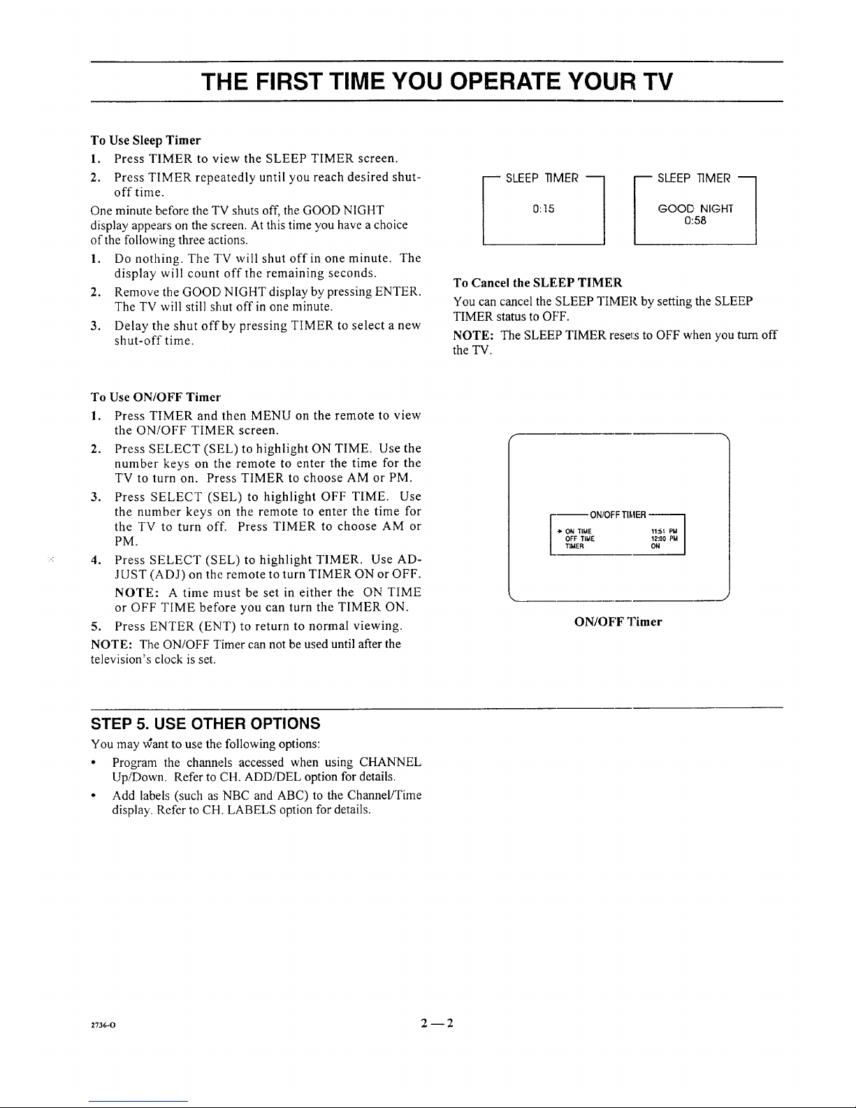
To Use Sleep Timer
1. Press TIMER to view the SLEEP TIMER screen.
2. Press TIMER repeatedly until you reach desired shut-
offtime.
One minute before the TV shuts off, the GOOD NIGHT
display appears on the screen. At this time you have a choice
of the following three actions.
1. Do nothing. The TV will shut off in one minute. The
display will count off the remaining seconds.
2. Remove the GOOD NIGHT display by pressing ENTER.
The TV will still shut off in one minute.
3. Delay tile shut off by pressing TIMER to select a new
shut-off time.
_ SLEEP TIMER ---1
0:15
_ SLEEP TIMER ---1
GOOD NIGHT
0:58
To Cancel the SLEEP TIMER
You can cancel the SLEEP TIMER by setting the SLEEP
TIMER status to OFF.
NOTE: The SLEEP TIMER rese_i:sto OFF when you_rn off
the TV.
To Use ON/OFF Timer
1. Press TIMER and then MENU on the remote to view
the ON/OFF TIMER screen.
2. Press SELECT (SEL) to highlight ON TIME. Use the
number keys on the remote to enter the time for the
TV to turn on. Press TIMER to choose AM or PM.
3. Press SELECT (SEL) to highlight OFF TIME. Use
the number keys on the remote to enter the time for
the TV to turn off. Press TIMER to choose AM or
PM.
4. Press SELECT (SEL) to highlight TIMER. Use AD-
JUST (ADJ) on the remote to turn TIMER ON or OFF.
NOTE: A time must be set in either the ON TIME
or OFF TIME before you can turn the TIMER ON.
5. Press ENTER (ENT) to return to normal viewing.
NOTE: The ON/OFF Timer can not be used until after the
television's clock is set.
--- ON/OFF TI_,tER--
-> ON TIME 11::51 PM
OFF TIME 12:O0 PM
TIMER ON
ON/OFF Timer
STEP 5. USE OTHER OPTIONS
You may ,,Cant to use the following options:
• Program the channels accessed when using CHANNEL
Up/Down. Refer to CH. ADDiDEL option for details.
• Add labels (such as NBC and ABC) to the Channel/Time
display. Refer to CH. LABELS option for details.
27s6-o 2--2
REMOTE CONTROL MODEL SC3820
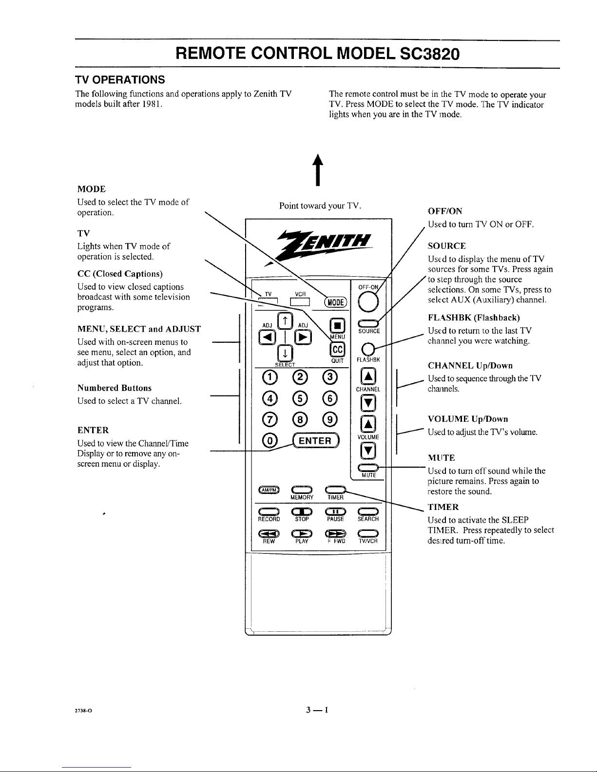
TV OPERATIONS
The following functions and operations apply to Zenith TV The remote control must be in the TV mode to operate your
models built after 1981. TV. Press MODE to select the TV mode. _,?heTV indicator
lights when you are in the TV mode.
MODE
Used to select the TV mode of
operation.
TV
Lights when TV mode of
operation is selected.
CC (Closed Captions)
Used to view closed captions
broadcast with some television
programs.
MENU, SELECT and ADJUST
Used with on-screen menus to
see menu, select an option, and
adjust that option.
Numbered Buttons
Used to select a TV channel.
ENTER
Used to view the Channel/Time
Display or to remove any on-
screen menu or display.
t
Point toward your TV.
® ® ®
®® ®
®® ®
OFF-ON/
E
MUTE
MEMORY
RECORD STOP PAUSE SEARCH
REW PLAY F FWD TVIVCR
/
OFF/ON
Used to turn TV ON or OFF.
:SO URCE
Used to display the menu of TV
sources for some TVs. Press again
to step through the source
sek,ctions. On some TVs, press to
select AUX (Auxiliary) channel.
FLASHBK (Flashback)
Used to return 1:othe last TV
channel you were watching.
J
,CHANNEL Up/I)own
:Usedto sequence through the TV
charnels.
'VOLUME Up!Down
!Used to adjust the TV's volume.
MUTE
Used to turn off sound while the
picture remains. Press again to
restore the sound.
'rIMER
Used to activate the: SLEEP
TIMER. Press repeatedly to select
Jes:i,red turn-off time.I I
2738-O 3 -- 1
REMOTE CONTROL MODEL SC3820
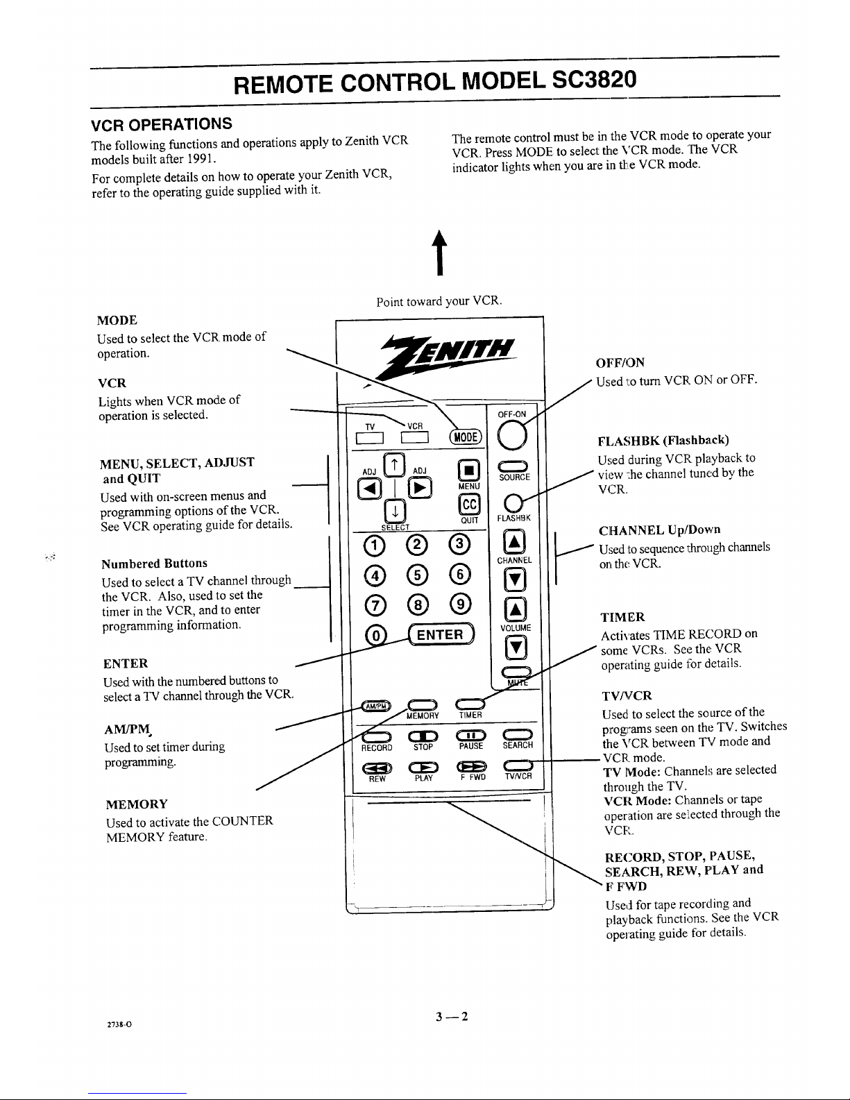
VCR OPERATIONS
The following functions and operations apply to Zenith VCR
models built after 1991.
For complete details on how to operate your Zenith VCR,
refer to the operating guide supplied with it.
The remote control must be in the VCR mode to operate your
VCR. Press MODE to select the VCR mode. The VCR
indicator lights when you are in tl:_,eVCR mode.
t
MODE
Used to select the VCR mode of
operation.
VCR
Lights when VCR mode of
operation is selected.
Point toward your VCR.
MENU, SELECT, ADJUST
and QUIT
Used with on-screen menus and
programming options of the VCR.
See VCR operating guide for details.
Numbered Buttons
Used to select a TV channel through
the VCR. Also, used to set the
timer in the VCR, and to enter
programming information.
ENTER
Used with the numbered buttons to
select a TV channel through the VCR.
Used to set timer during
programming.
MEMORY
Used to activate the COUNTER
MEMORY feature.
ADJ _ ADJ _:_
N
QUIT
SELECT
®® ®
®®®
®®®
_._ENTER )
SOURCE
01
FLASHBK
IAI
CHANNEL
Ill
IAI
VOLUME
IV'l
RECORD STOP PAUSE SEARCH
CE) (EE) L..J
REW PLAY F FWD TVNDB
OFF/ON
J Used 'l:oturn VCR ON or OFF.
FLASHBK (Flashback)
Used during VCP playback to
J view :he channel tuned by the
VCR.
CHANNEL Up/Down
Used to sequence _arough channels
on the VCR.
TIM ER
Activates TIME RECORD on
some VCRs. See the: VCR
operating guide for details.
TV/VCR
Used to select the source of the
programs seen on the TV. Switches
the VCR between TV mode and
VCR mode.
TV lVlode: Channels are selected
through the TV.
VCR Mode: Channels or tape
operation are se:iected through the
VCP.
RECORD, STOP, PAUSE,
SEARCH, REW, PLAY and
F FWD
Used for tape recording and
playback functions. See the VCR
operating guide for details.
:Tss-o 3 -- 2
 Loading...