


R56W36

© Copyright 2003, Zenith Electronics Corporation.
Installation and Operating Guide | Warranty
Model Numbers | R49W36, R56W36 | Projection TVs
PAGE 2
206-03865
WARNING:
TO REDUCE THE RISK OF ELECTRIC SHOCK DO NOT REMOVE COVER (OR BACK). NO USER SERVICEABLE PARTS INSIDE.
REFER TO QUALIFIED SERVICE PERSONNEL.
The lightning flash with arrowhead symbol, within an equilateral triangle, is intended to alert the user to the presence
of uninsulated “dangerous voltage” within the product’s enclosure that may be of sufficient magnitude to constitute a
risk of electric shock to persons.
The exclamation point within an equilateral triangle is intended to alert the user to the presence of important operating
and maintenance (servicing) instructions in the literature accompanying the appliance.
WARNING:
TO PREVENT FIRE OR SHOCK HAZARDS, DO NOT EXPOSE THIS PRODUCT TO RAIN OR MOISTURE.
POWER CORD POLARIZATION:
CAUTION: TO PREVENT ELECTRIC SHOCK, MATCH WIDE BLADE OF PLUG TO WIDE SLOT, FULLY INSERT.
ATTENTION: POUR ÉVITER LES CHOCS ÉLECTRIQUES, INTRODUIRE LA LAME LA PLUS LARGE DE LA FICHE DANS LA BORNE
CORRESPONDANTE DE LA PRISE ET POUSSER JUSQU’AU FOND.
NOTE TO CABLE/TV INSTALLER:
This reminder is provided to call the CATV system installer’s attention to Article 820-40 of the National Electric Code
(U.S.A.). The code provides guidelines for proper grounding and, in particular, specifies that the cable ground shall be
connected to the grounding system of the building, as close to the point of the cable entry as practical.
REGULATORY INFORMATION:
This equipment, trade name Zenith, model number, R49W36/R56W36, has been tested and found to comply with the
limits for a Class B digital device, pursuant to Part 15 of the FCC Rules. These limits are designed to provide reasonable
protection against harmful interference when the equipment is operated in a residential installation. This equipment
generates, uses and can radiate radio frequency energy and, if not installed and used in accordance with the instruction
manual, may cause harmful interference to radio communications. However, there is no guarantee that interference will
not occur in a particular installation. If this equipment does cause harmful interference to radio or television reception,
which can be determined by turning the equipment off and on, the user is encouraged to try to correct the interference
by one or more of the following measures:
• Reorient or relocate the receiving antenna.
• Increase the separation between the equipment and receiver.
• Connect the equipment into an outlet on a circuit different from that to which the
receiver is connected.
• Consult the dealer or an experienced radio/TV technician for help.
Any changes or modifications not expressly approved by the party responsible for compliance could void the user’s
authority to operate the equipment.
The responsible party for this device compliance is:
Zenith Electronics Corporation
2000 Millbrook Drive
Lincolnshire, IL 60069
Digital TV Hotline:
1-847-941-8000
CAUTION:
Do not attempt to modify this product in any way without written authorization from Zenith Electronics Corporation.
Unauthorized modification could void the user’s authority to operate this product.
2003 Zenith Electronics Corporation. All rights reserved.
WARNING
RISK OF ELECTRIC SHOCK
DO NOT OPEN

PAGE 3
206-03865
Important safeguards for you and your new product
Your product has been manufactured and tested with your safety in mind. However, improper use can result in electrical
shock or fire hazards. To avoid defeating the safeguards that have been built into your new product, please read and
observe the following safety points when installing and using your new product, and save them for future reference.
Observing the simple precautions discussed in this manual can help you get many years of enjoyment and safe operation
that are built into your new product.
This product complies with all applicable U.S. Federal safety requirements, and those of the Canadian Standards Association.
(Continued on next page)
1. Read Instructions
All the safety and operating instructions should be read
before the product is operated.
2. Follow Instructions
All operating and use instructions should be followed.
3. Retain Instructions
The safety and operating instructions should be retained
for future reference.
4. Heed Warnings
All warnings on the product and in the operating instruc-
tions should be adhered to.
5. Cleaning
Unplug this product from the wall outlet before cleaning.
Do not use liquid cleaners or aerosol cleaners. Use a damp
cloth for cleaning.
6. Water and Moisture
Do not use this product near water, for example, near a
bath tub, wash bowl, kitchen sink, or laundry tub, in a
wet basement, or near a swimming pool.
7. Accessories, Carts, and Stands
Do not place this product on a slippery or tilted surface,
or on an unstable cart, stand, tripod, bracket, or table.
The product may slide or fall, causing serious injury to a
child or adult, and serious damage to the product. Use
only with a cart, stand, tripod, bracket, or table recom-
mended by the manufacturer, or sold with the product.
Any mounting of the product should follow the manufac-
turer’s instructions, and should use a mounting accessory
recommended by the manufacturer.
8. Transporting Product
A product and cart combination should be moved with
care. Quick stops, excessive force, and uneven surfaces
may cause the product and cart combination to overturn.
9. Attachments
Do not use attachments not recommended by the product
manufacturer as they may cause hazards.
10. Ventilation
Slots and openings in the cabinet are provided for ventila-
tion and to ensure reliable operation of the product and to
protect it from overheating, and these openings must not
be blocked or covered. The openings should never be
blocked by placing the product on a bed, sofa, rug, or
other similar surface. This product should not be placed in
a built-in installation such as a bookcase or rack unless
proper ventilation is provided or the manufacturer’s
instructions have been adhered to.
11. Power Sources
This product should be operated only from the type of
power source indicated on the marking label. If you are
not sure of the type of power supply to your home, con-
sult your product dealer or local power company. For prod-
ucts intended to operate from battery power, or other
sources, refer to the operating instructions.
12. Power-Cord Polarization
This product is equipped with a polarized alternating-cur-
rent line plug (a plug having one blade wider than the
other). This plug will fit into the power outlet only one
way. This is a safety feature. If you are unable to insert
the plug fully into the outlet, try reversing the plug. If
the plug should still fail to fit, contact your electrician to
replace your obsolete outlet. Do not defeat the safety pur-
pose of the polarized plug.
13. Power-Cord Protection
Power-supply cords should be routed so that they are not
likely to be walked on or pinched by items placed upon or
against them, paying particular attention to cords at
plugs, convenience receptacles, and the point where they
exit from the product.
PORTABLE CART WARNING
IMPORTANT SAFETY INSTRUCTIONS
PAGE 4
206-03865
(Continued from previous page)
14. Outdoor Antenna Grounding
If an outside antenna or cable system is connected to the
product, be sure the antenna or cable system is grounded
to provide protection against voltage surges and built-up
static charges. Article 810 of the National Electrical Code
(U.S.A.), ANSI/ NFPA 70 provides information with regard
to proper grounding of the mast and supporting structure,
grounding of the lead-in wire to an antenna discharge
unit, size of grounding conductors, location of antenna-
discharge unit, connection to grounding electrodes, and
requirements for the grounding electrode.
15. Lightning
For added protection for this product (receiver) during a
lightning storm, or when it is left unattended and unused
for long periods of time, unplug it from the wall outlet and
disconnect the antenna or cable system. This will prevent
damage to the product due to lightning and power-line
surges.
16. Power Lines
An outside antenna system should not be located in the
vicinity of overhead power lines or other electric light or
power circuits, or where it can fall into such power lines or
circuits. When installing an outside antenna system,
extreme care should be taken to keep from touching such
power lines or circuits as contact with them might be
fatal.
17. Overloading
Do not overload wall outlets and extension cords as this
can result in a risk of fire or electric shock.
18. Object and Liquid Entry
Never push objects of any kind into this product through
openings as they may touch dangerous voltage points or
short-out parts that could result in a fire or electric shock.
Never spill liquid of any kind on the product.
19. Servicing
Do not attempt to service this product yourself as opening
or removing covers may expose you to dangerous voltage
or other hazards. Refer all servicing to qualified service
personnel.
20. Damage Requiring Service
Unplug this product from the wall outlet and refer servic-
ing to qualified service personnel under the following con-
ditions:
a. If the power-supply cord or plug is damaged.
b. If liquid has been spilled, or objects have fallen into
the product.
c. If the product has been exposed to rain or water.
d. If the product does not operate normally by following
the operating instructions. Adjust only those controls that
are covered by the operating instructions as an improper
adjustment of other controls may result in damage and will
often require extensive work by a qualified technician to
restore the product to its normal operation.
e. If the product has been dropped or the cabinet has
been damaged.
f. If the product exhibits a distinct change in perfor-
mance.
21. Replacement Parts
When replacement parts are required, be sure the service
technician has used replacement parts specified by the
manufacturer or have the same characteristics as the origi-
nal part. Unauthorized substitutions may result in fire,
electric shock, or other hazards.
22. Safety Check
Upon completion of any service or repairs to this product,
ask the service technician to perform safety checks to
determine that the product is in proper operating condi-
tion.
23. Wall or Ceiling Mounting
The product should be mounted to a wall or ceiling only as
recommended by the manufacturer. The product may slide
or fall, causing serious injury to a child or adult, and seri-
ous damage to the product.
24. Heat
The product should be situated away from heat sources
such as radiators, heat registers, stoves, or other products
(including amplifiers) that produce heat.
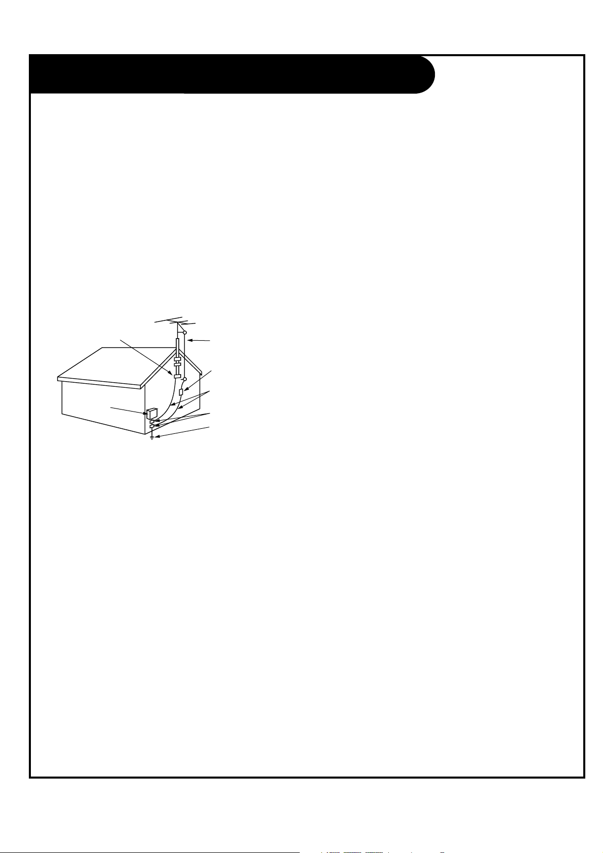
Antenna Lead in Wire
Antenna Discharge Unit
(NEC Section 810-20)
Grounding Conductor
(NEC Section 810-21)
Ground Clamps
Power Service Grounding
Electrode System (NEC
Art 250, Part H)
Ground Clamp
Electric Service
Equipment
Example of Grounding According to National Electrical
Code Instructions
Fig. 1
NEC - National Electrical Code
IMPORTANT SAFETY INSTRUCTIONS

PAGE 5
206-03865
Table of Contents
Safety Warnings . . . . . . . . . . . . . . . . . . . . . . . . . . . .2
Important Safety Instructions . . . . . . . . . . . . . . . . .3-4
Step 1. Hook Up TV
Front Controls Panel . . . . . . . . . . . . . . . . . . . . . . . . .6
Rear Connections Panel . . . . . . . . . . . . . . . . . . . . . . .7
Front Connections Panel . . . . . . . . . . . . . . . . . . . . . .8
ANT/CABLE Service Hookup . . . . . . . . . . . . . . . . . . . .9
CABLE BOX Connections . . . . . . . . . . . . . . . . . . . . . .10
VCR Connections . . . . . . . . . . . . . . . . . . . . . . . . . . .11
DVD Player . . . . . . . . . . . . . . . . . . . . . . . . . . . . . .12
DBS Input . . . . . . . . . . . . . . . . . . . . . . . . . . . . . . .13
Monitor Out Setup . . . . . . . . . . . . . . . . . . . . . . . . .14
Turning the TV on . . . . . . . . . . . . . . . . . . . . . . . . . .15
On-Screen Displays . . . . . . . . . . . . . . . . . . . . . . . . .15
Remote Control Functions In TV Mode . . . . . . . . . . .16-17
Step 2. Customize your TV’s Features
SETUP Menu
EZ Scan (Channel Search) . . . . . . . . . . . . . . . . . . . .18
Channel Edit . . . . . . . . . . . . . . . . . . . . . . . . . . . .19
Fine Tuning Adjustment . . . . . . . . . . . . . . . . . . . . .20
VIDEO Menu . . . . . . . . . . . . . . . . . . . . . . . . . . .21-23
AUDIO Menu . . . . . . . . . . . . . . . . . . . . . . . . . . .24-25
TIME Menu
Auto Clock Setup . . . . . . . . . . . . . . . . . . . . . . . . .26
Manual Clock Setup . . . . . . . . . . . . . . . . . . . . . . . .27
TV Turn Off Time Setup . . . . . . . . . . . . . . . . . . . . .28
TV Turn On Time Setup . . . . . . . . . . . . . . . . . . . . . .29
Sleep Timer Setup . . . . . . . . . . . . . . . . . . . . . . . . .30
Auto off . . . . . . . . . . . . . . . . . . . . . . . . . . . . . . .31
SPECIAL Menu
On-Screen Menus Language . . . . . . . . . . . . . . . . . . .32
Main Picture Source Selection . . . . . . . . . . . . . . . . . 33
PIP (Picture-In-Picture) Options . . . . . . . . . . . . . . .34
POP (Picture-out-of-Picture) Source . . . . . . . . . . . . .35
Twin Picture . . . . . . . . . . . . . . . . . . . . . . . . . . . .36
Captions . . . . . . . . . . . . . . . . . . . . . . . . . . . . . . .37
Captions/Text . . . . . . . . . . . . . . . . . . . . . . . . . . . .38
Aspect Ratio Control . . . . . . . . . . . . . . . . . . . . . . .39
Key Lock . . . . . . . . . . . . . . . . . . . . . . . . . . . . . . .40
Auto Convergence . . . . . . . . . . . . . . . . . . . . . . . . .41
Auto Move . . . . . . . . . . . . . . . . . . . . . . . . . . . . . .42
LOCK Menu
Parental Lock Setup . . . . . . . . . . . . . . . . . . . . .43-45
Step 3. Miscellaneous
Programming the Remote . . . . . . . . . . . . . . . . . . . . .46
Programming Codes . . . . . . . . . . . . . . . . . . . . . .47-50
Maintenance . . . . . . . . . . . . . . . . . . . . . . . . . . .51-52
Troubleshooting . . . . . . . . . . . . . . . . . . . . . . . . .53-54
Glossary . . . . . . . . . . . . . . . . . . . . . . . . . . . . . .55-56
Product Specifications . . . . . . . . . . . . . . . . . . . . . .57
Notes . . . . . . . . . . . . . . . . . . . . . . . . . . . . . . .58-59
Warranty . . . . . . . . . . . . . . . . . . . . . . . . . .Back cover
Note: Design and specifications are subject to change without prior notice.
PAGE 6
206-03865
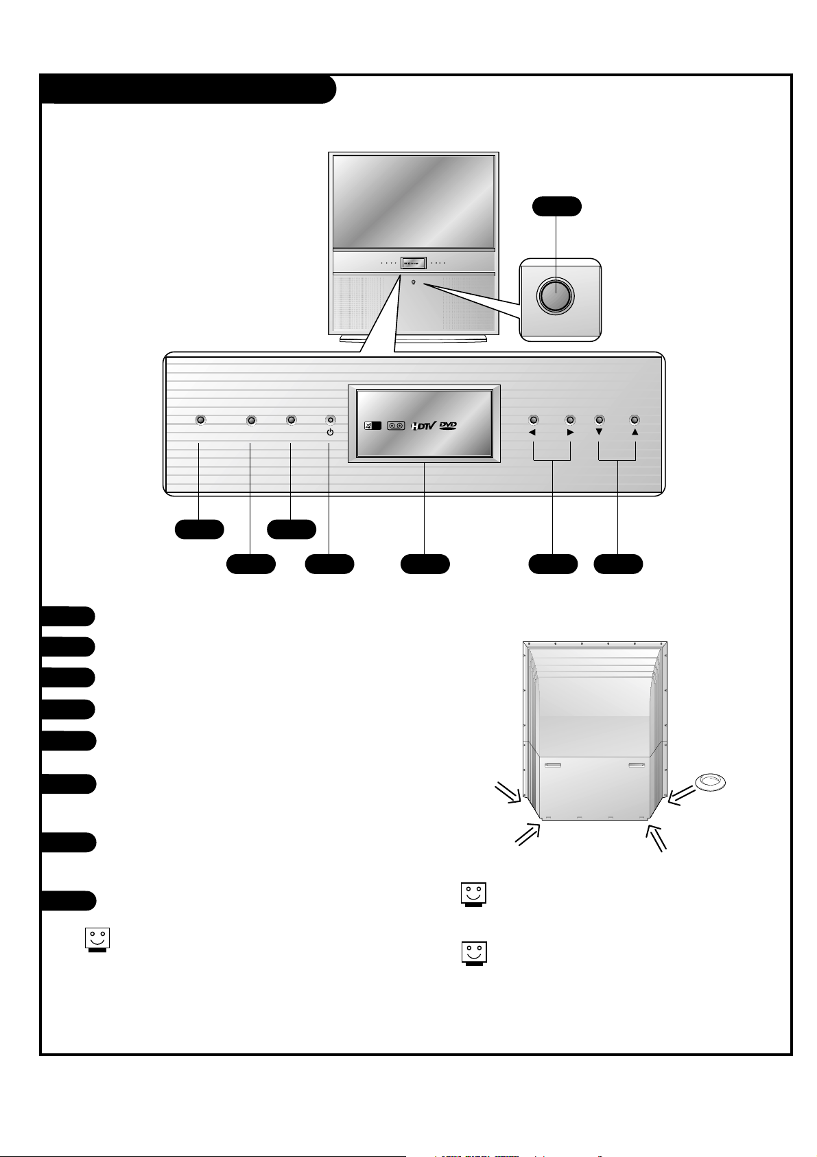
Front Panel Controls
CATV
VIDEO
CATV
VIDEO
tv/video menu enter vol ch
on/off
On/Off
TV/VIDEO
Menu
Enter
Standby indicator (Illuminates brightly when the TV is in
standby mode. Dims when the TV is switched on.)
LED (Light Emitting Diodes) Displays
Illuminate brightly when the set is switched on.
LEDs light when source is selected or feature is present.
VOLUME UP / DOWN
Volume(
G) button increases the level of sound and
volume(
F) button decreases the level of sound.
CHANNEL UP / DOWN
1
2
3
4
These buttons work just as they do on your
remote control.
2
1
3 5 6 7
4
8
5
6
7
8
Casters (On the bottom)
Turn and move the TV easily.
To fix TV’s position, install the 4 stoppers under the
roller casters to prevent the TV from being moved.
Stopper
PAGE 7
206-03865
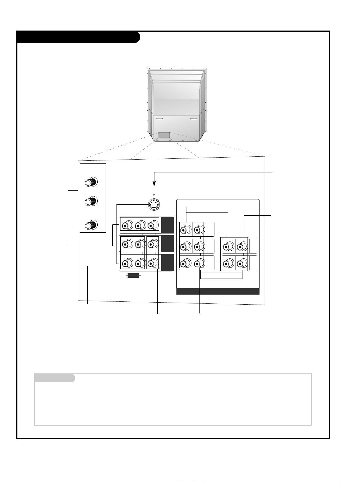
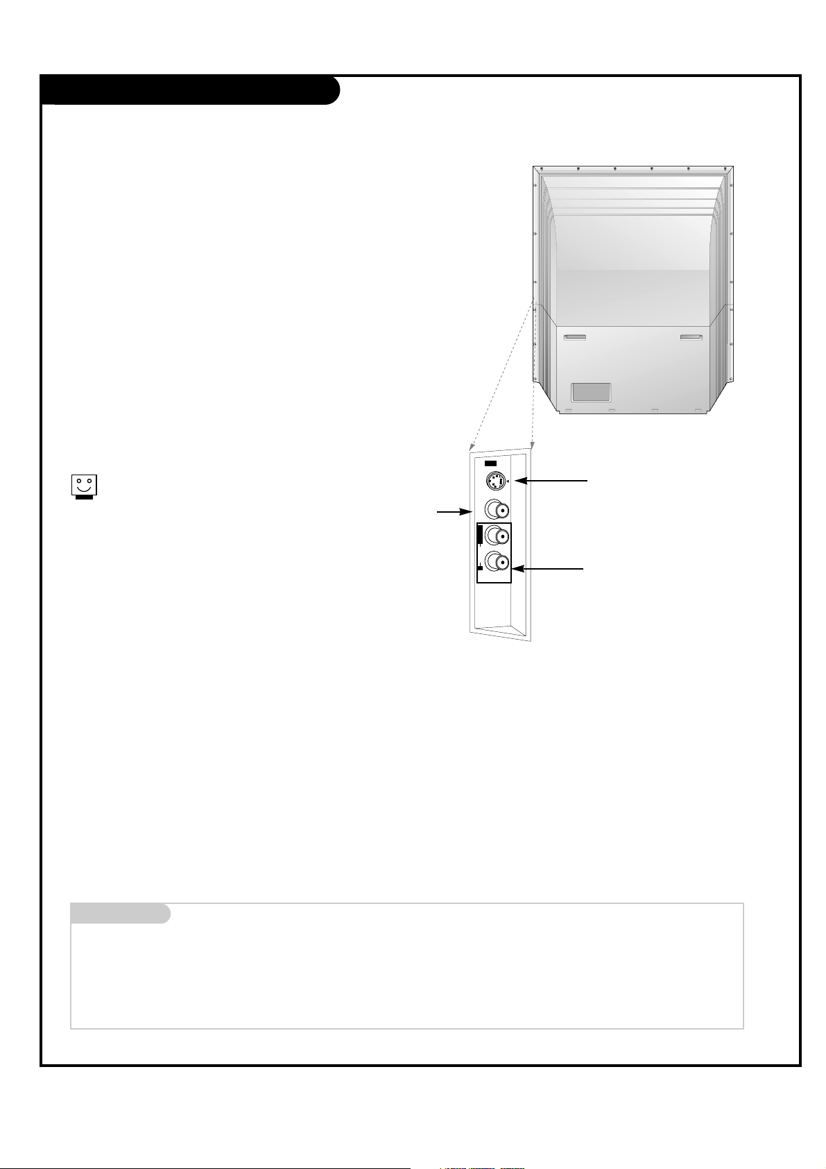
Rear Connections Panel
Mini glossary
JACK A connection on the back of a TV, VCR, or any other A/V device. This includes the RF jack and the Audio/Video jacks that are color-
coded.
SIGNAL Picture and sound traveling through cable, or over the air, to your television screen.
PR
S-VIDEO
ANT/CABLE1
INPUT
ANT/CABLE2
INPUT
LOOP OUT
COMPONENT INPUT 1
(480i/480p/720p/1080i)
COMPONENT INPUT 2
(480i/480p/720p/1080i)
PB
Y
(R)
(L)
(R)
(L)
VIDEO
AUDIO
(MONO)
AUDIO
DVD/DTV INPUT
MNT
OUT
IN 2
IN 1
S-VIDEO In
A connection available
with some high-end
equipment that provides
even better picture
quality for Video 1.
RF Connector:
Antenna/Cable 1,
Antenna/Cable 2,
and Loop Out
Used to connect analog
cable or antenna signals
to the television, either
directly or through your
cable box.
Video 1 and 2 Inputs
Connects the video signals
from various types of
equipment.
Y, Pb, Pr
DVD Component Video and HD
Component Video
Some top-of-the-line DVD players use what
is called “component video,” for extremely
accurate picture reproduction. Refer to
your DVD manual for further information.
Connecting cables to your TV.
Monitor Out
Connects to a second
TV or Monitor
.
(Monitor out is not
available if you set
lock “On” in Lock
menu.)
Left/Right Audio
Used for stereo sound
from various types of
equipment.
Component Left/Right
Audio
Used for stereo sound from
various types of equipment.
PAGE 8
206-03865
Front Connection Panel (Video 3)
Video3 Panel
VIDEO
S-VIDEO
AUDIO
L/MONO
IN 3
R
There are four jacks on the right front side
behind the screen on your projection TV that
make connecting Audio/Video devices like
video games and camcorders very simple.
The jacks are like those found on the back
jack connection panel. This means that most
equipment that connects to those types of
jacks on the rear jackpack, may be connected
to the front connection panel (Video3).
To use the front jacks as the signal source,
select them using Main Source menu as
described on page 33. They will be named
“Video 3” in the Main Source menu.
Left/Right Audio
Used for stereo sound from various
types of equipment.
Video
Connects the video
signals from any
piece of equipment.
S-Video
A connection available on some very
high-end equipment that provides
better picture quality than video
input.
When you select Video3 (Front
Video or Front S-Video, the Front
audio) inputs are automatically
selected as well.
CAUTION: Do not connect to both Video and
S-Video at the same time. Connect
either Video or S-Video only.
Mini glossary
A/V CABLES Audio/Video cables. Three cable connector—Right audio (red), Left audio (white), and Video (yellow). A/V cables are used for stereo
playback of videocassettes and for higher quality picture and sound from other A/V devices.
A/V DEVICE Any device that produces video (picture) and/or audio (sound) (VCR, DVD, cable box, or television).
PAGE 9
206-03865
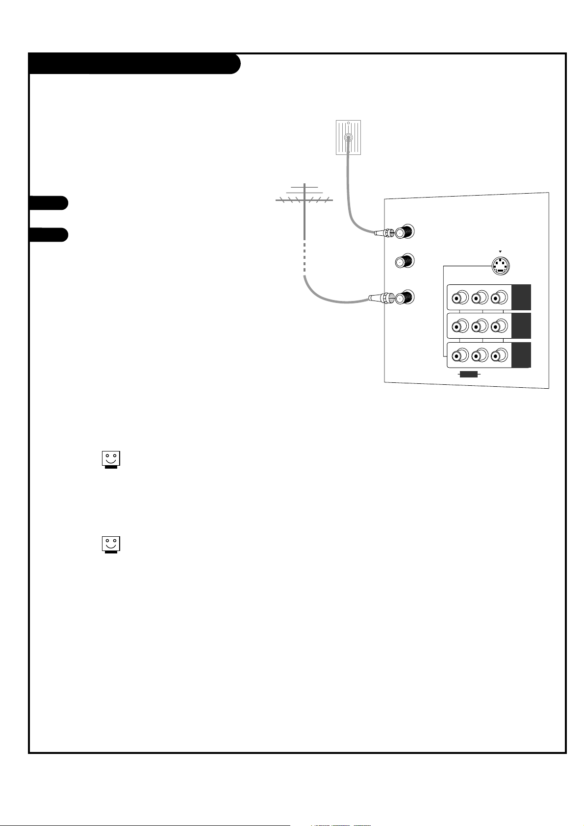
ANT / Cable Service Hookup
1
Connect an antenna and/or cable service to
your TV as shown.
Turn to page 18 to do a channel search
with EZ Scan for ANT / CABLE
connection(s).
For best signal reception, it is recommended to have your Antenna professionally adjusted.
2
If you receive your RF signal
through an antenna that is several
years old and connects with two
small prongs, you will need to pur-
chase a 300 to 75 ohm adapter. It
should be available from your local
electronics dealer.
Zenith recommends using a 75
ohm cable for your antenna con-
nections in order to prevent
interference.
S-VIDEO
ANT/CABLE1
INPUT
ANT/CABLE2
INPUT
LOOP OUT
(R)
(L)
VIDEO
(MONO)
AUDIO
MNT
OUT
IN 2
IN 1
Antenna
Cable TV
Wall jack
RF coaxial wire
(75 ohm)
RF coaxial wire
(75 ohm)
PAGE 10
206-03865
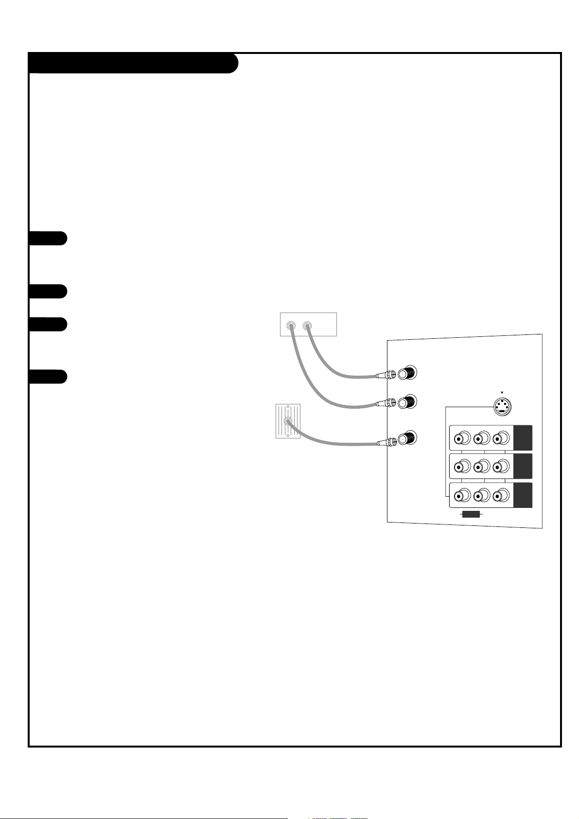
Cable Box Connections
Locate the Antenna/Cable 2 jack on the
back of your TV. Connect the cable that
runs from the wall directly or antenna to
the jack. Now find the Loop Out jack.
Connect the cable from this jack to the
Input jack on the back of your cable box.
Locate the Output jack on the back of
your cable box. Connect this to the
Antenna/Cable 1 jack on the back of your
TV.
To view the premium stations, press the
TV/VIDEO button on your remote and
select the other Cable source (Ant/Cable
1). Then tune the channel number on
your cable box for HBO, CINEMAX, SHOW-
TIME, etc.
To view non-premium channels press the
TV/VIDEO button and select Ant/Cable 2.
Then run EZ Scan to find all available
channels and store them in memory.
This can be combined with any other
equipment you may want to hook up, see
following pages. Connect cable service
wire directly to the TV, loop out from the
TV, then to the cable box. From there, the
cable box output connects to the next
device in the connection series, until the
last device, which connects back to the
Antenna/Cable 1 jack on the TV.
1
2
3
4
Some cable services require the use of a cable box to decode pre-
mium channels and pay-per-view. Using the Loop Out to Decoder
connection option, and programming your remote, you can con-
nect your cable box so that you only need your MBR remote to
tune to premium and non-premium channels. By connecting a
cable box directly to your TV, as shown to the LOOP OUT, you
make the cable box another available channel tuning source using
your remote.
S-VIDEO
ANT/CABLE1
INPUT
ANT/CABLE2
INPUT
LOOP OUT
(R)
(L)
VIDEO
(MONO)
AUDIO
MNT
OUT
IN 2
IN 1
In
Out
Cable box
Cable TV Wall jack
PAGE 11
206-03865
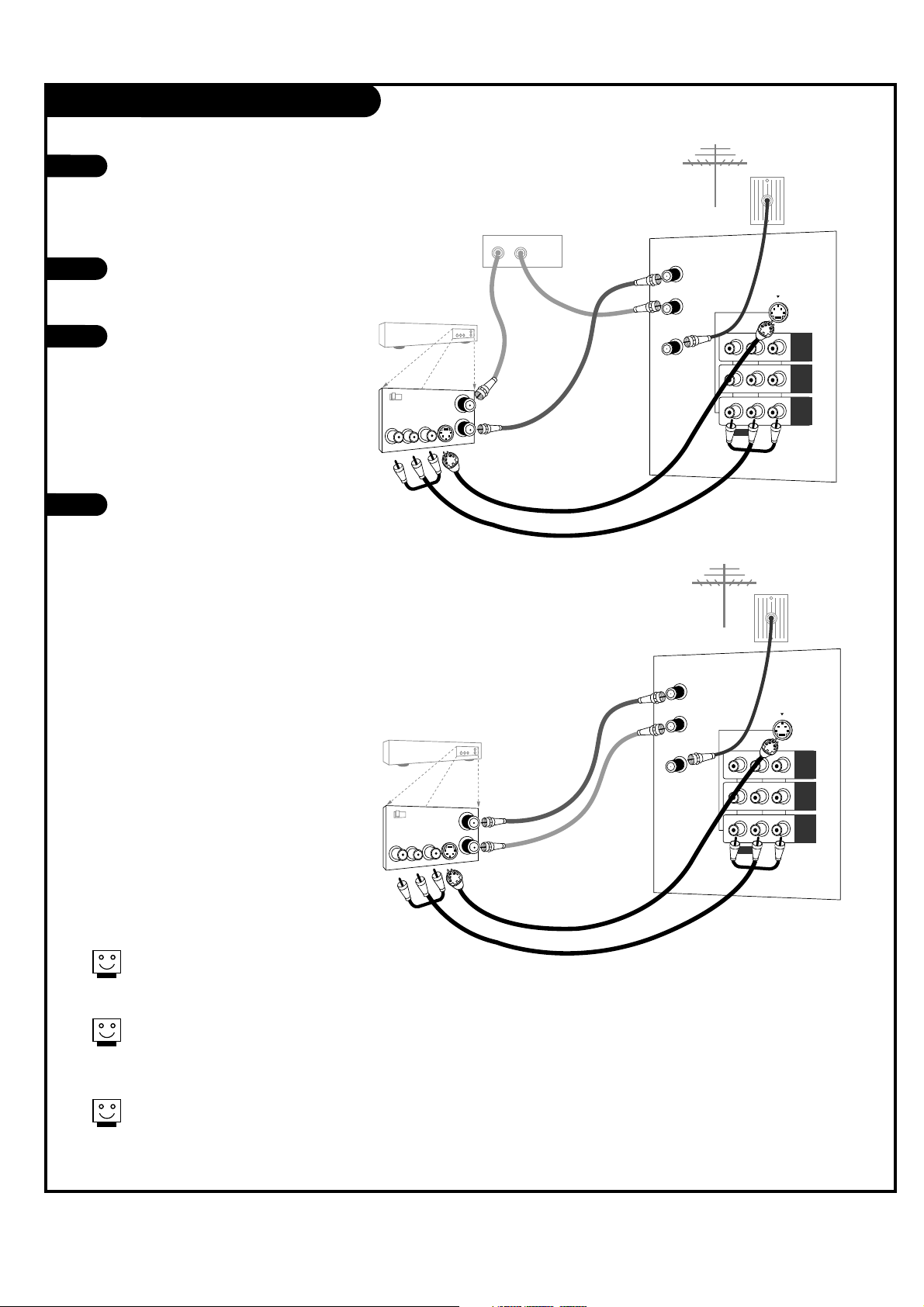
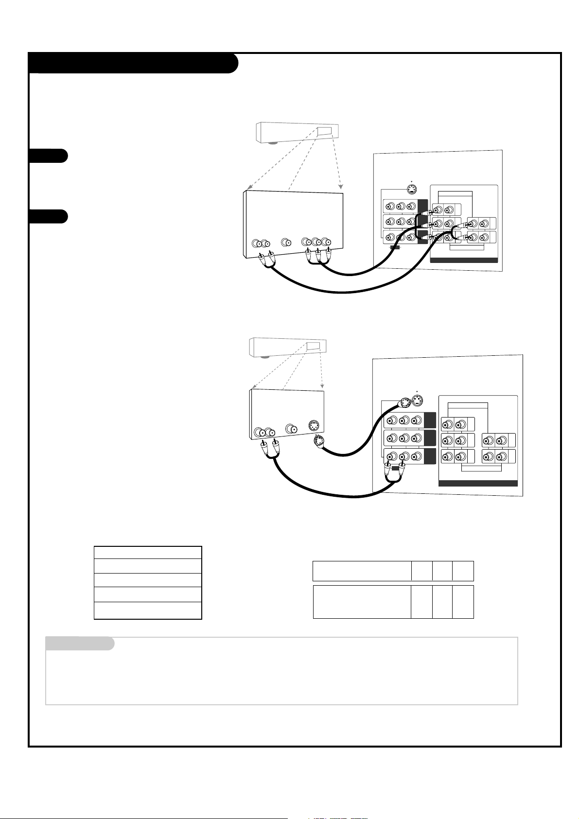
VCR Connections
1
2
3
4
Locate the Antenna/Cable 2 jack on
the back of your TV. Connect the cable
that runs from the wall or antenna to
the jack.
Now find the Loop Out jack.
Connect the cable from this jack to
the Input jack on the back of your
cable box.
Locate the Output jack on the back of
your cable box. Connect this to the RF
or VHF/UHF/CATV In jack on the back
of your VCR.
If you want to connect VCR to the TV
directly, connect the cable from the
Loop Out jack to the RF or
VHF/UHF/CATV In jack on the back of
your VCR.
Find the composite video and
audio jacks on the back of your
VCR, and connect them following
the instructions provided with
your equipment.
You may connect either the com-
posite video or the S-Video cables
to your TV. (Do not connect BOTH
the composite video and the S-
Video cables. In the event that
you connect both composite video
and the S-Video cables, only the
S-Video will work.)
To hear stereo sound from cable or your VCR,
you will need to connect A/V cables as well as
the wire that runs from the VCR to your TV.
If you want to receive your signals on Channel
3 or 4, locate the Out to TV jack on your VCR.
Connect a cable from the Out to TV jack to the
Antenna/Cable 1 jack on the back of your TV.
After connecting external equipment to the TV, don’t display a still picture for a long time on the screen.
Doing so may damage the TV screen.
In
Out
Audio
L
R
Video
3 4
S-Video
S-VIDEO
ANT/CABLE1
INPUT
ANT/CABLE2
INPUT
LOOP OUT
(R)
(L)
VIDEO
(MONO)
AUDIO
MNT
OUT
IN 2
IN 1
Antenna
RF coaxial wire
(75 ohm)
Round wire
(75 ohm)
A/V cables
not included
with TV
or
VCR
Back AV panel
Cable TV
Wall jack
In
Out
Audio
L
R
Video
3 4
S-Video
In
Out
S-VIDEO
ANT/CABLE1
INPUT
ANT/CABLE2
INPUT
LOOP OUT
(R)
(L)
VIDEO
(MONO)
AUDIO
MNT
OUT
IN 2
IN 1
Antenna
RF coaxial wire
(75 ohm)
Round wire
(75 ohm)
A/V cables
not included
with TV
or
Cable box
VCR
Back AV panel
Cable TV
Wall jack
PAGE 12
206-03865
DVD Player
Mini glossary
COMPONENT VIDEO Some video equipment uses three separate lines (Y, P
B, PR) to more precisely reproduce images. Your manual will explain how
this relates to your equipment.
1
2
Component 1 (or 2) Input
Y PB PR
1920X1080i
1280X720p
720X480p
720X480i
Audio
LR
Dolby Digital
Out
Component Video
PR
S-VIDEO
COMPONENT INPUT 1
(480i/480p/720p/1080i)
COMPONENT INPUT 2
(480i/480p/720p/1080i)
PB
Y
(R)
(L)
(R)
(L)
VIDEO
AUDIO
(MONO)
AUDIO
DVD/DTV INPUT
MNT
OUT
IN 2
IN 1
PR
S-VIDEO
COMPONENT INPUT 1
(480i/480p/720p/1080i)
COMPONENT INPUT 2
(480i/480p/720p/1080i)
PB
Y
(R)
(L)
(R)
(L)
VIDEO
AUDIO
(MONO)
AUDIO
DVD/DTV INPUT
MNT
OUT
IN 2
IN 1
Audio
LR
S-Video
Dolby Digital
Out
Component input jacks
on the Monitor
Y
PB
PR
Video output jacks
of DVD player
Y
Y
Y
Y
Pb
B-Y
Cb
PB
Pr
R-Y
Cr
P
R
• Component Input ports
You can get better picture quality if you
connect DVD player with component input
ports as below.
A/V cables
not included
with TV
A/V cables
not included
with TV
DVD player
DVD player
Back AV panel
Back AV panel
Find the audio and component or
S-Video jacks on the back of your
DVD Player and connect them fol-
lowing the instructions provided
with your equipment.
You may connect either the com-
posite video or the S-Video cables
to your TV. Do not connect both
the composite and the S-Video.
Some high-end DVD players use
a picture reproduction system
called “component video.” If
your DVD player has component
output, use the connector
marked “COMPONENT 1/2” on
the jack panel. Please refer to
your DVD manual for proper
installation.
PAGE 13
206-03865
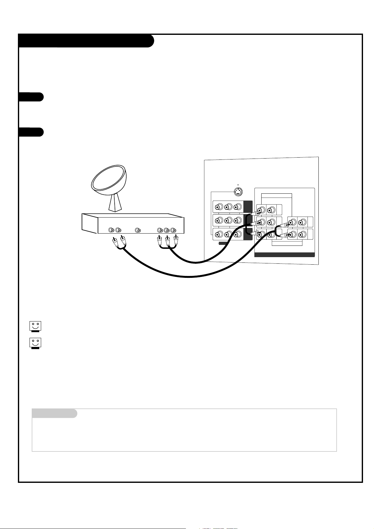
DBS Hookup
Find the audio and Y, PB, PR jacks on the
back of your DBS receiver and connect
them following the instructions provided
with your equipment.
Connect these cables to your TV as shown.
1
2
The DTV shows the sharpest picture in 720p mode.
To watch DTV, connect a HD-SET TOP box to COMPONENT
INPUT1 or 2 of your TV.
Audio
L R
Component Out
Y Pb Pr
Dolby Digital
Out
PR
S-VIDEO
COMPONENT INPUT 1
(480i/480p/720p/1080i)
COMPONENT INPUT 2
(480i/480p/720p/1080i)
PB
Y
(R)
(L)
(R)
(L)
VIDEO
AUDIO
(MONO)
AUDIO
DVD/DTV INPUT
MNT
OUT
IN 2
IN 1
DBS Receiver
Mini glossary
DBS (Direct Broadcast Satellite), receives TV signals from a satellite.
DTV (Digital TV), receives digital program signals and turns them into picture and sound.
PAGE 14
206-03865
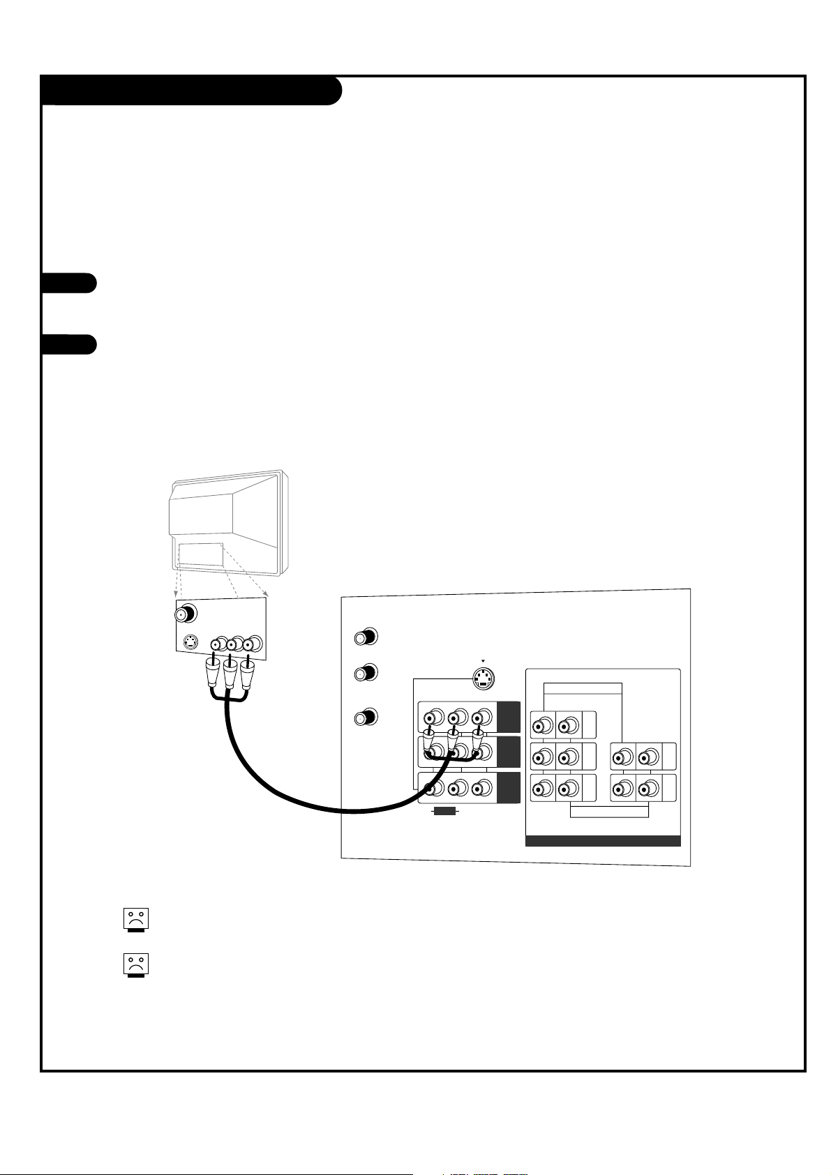
Monitor Out Setup
Your TV has a special signal output capa-
bility which allows you to hook up a sec-
ond TV or monitor.
Just connect the second TV or monitor to
the MNT OUT Audio/Video jacks located on
the back of your TV. See the Operating
Manual of the second TV or monitor for
further details regarding that device’s
input settings.
1
2
Audio
Video
S-Video
PR
S-VIDEO
ANT/CABLE1
INPUT
ANT/CABLE2
INPUT
LOOP OUT
COMPONENT INPUT 1
(480i/480p/720p/1080i)
COMPONENT INPUT 2
(480i/480p/720p/1080i)
PB
Y
(R)
(L)
(R)
(L)
VIDEO
AUDIO
(MONO)
AUDIO
DVD/DTV INPUT
MNT
OUT
IN 2
IN 1
Component 1 - 2 input sources for main picture
cannot be used for Monitor Out.
Monitor Out is not available if you set lock
“On” in Lock menu.
A/V cables
not included
with TV
Second TV
PAGE 15
206-03865
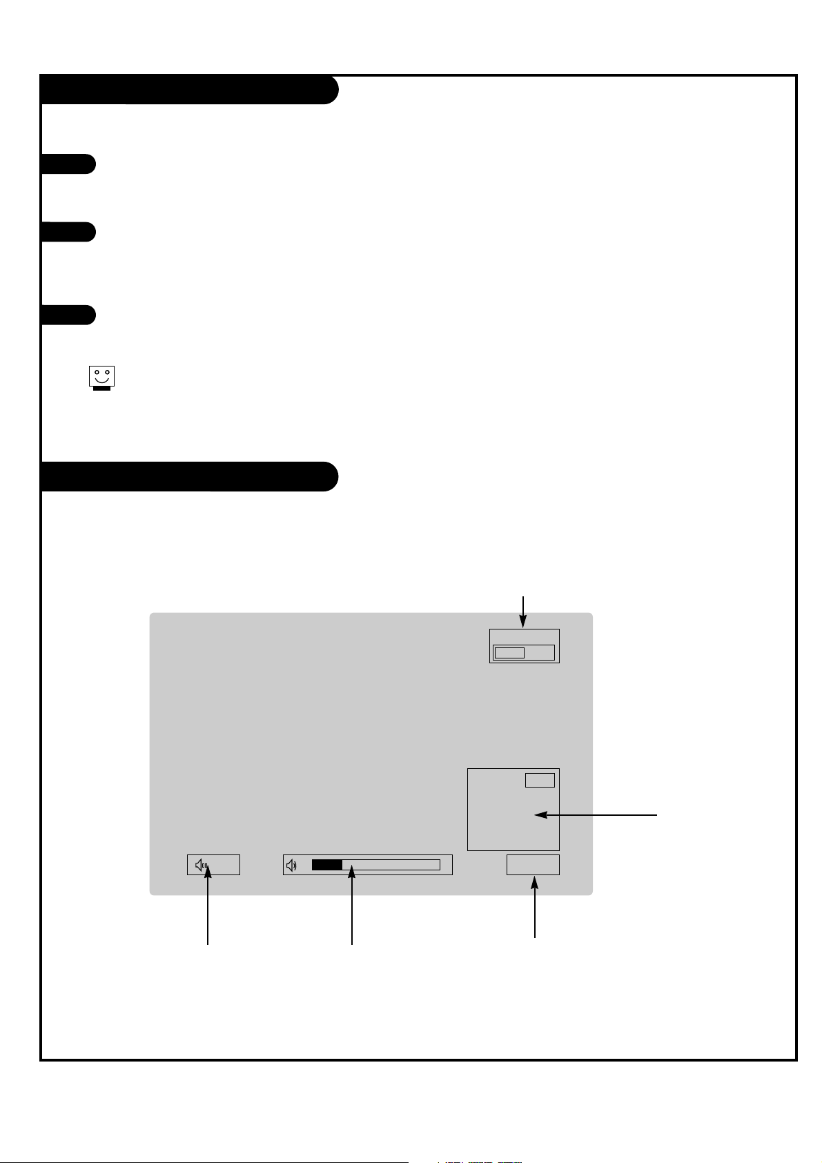
Turning the TV On
On-Screen Displays
This page describes your on-screen display and information banner options.
First, connect antenna cable and power cord correctly. At this moment, the TV switches to standby mode.
In standby mode to turn TV on, press the POWER, CH UP/DOWN, TV/VIDEO, COMP or number buttons on the
remote control or ON/OFF, CH UP/DOWN or ENTER on the TV.
Select the viewing source by using TV/VIDEO or COMP on the remote control.
This TV is programmed to remember which mode it was last set to, even if you turn the TV off.
Note: See page 18 if you have not auto programmed the TV to receive channels in your local broadcast
area.
When finished using the TV, press the POWER button on the remote control. The TV reverts to standby
mode.
1
2
3
If you will be away on vacation, disconnect the power plug from the wall power outlet.
10
Mute
TV 15
MONO
10:00 AM
TV15
PIP Display
This display
appears when PIP
is active.
Volume
Volume level is displayed
while adjusting the sound.
Mute
Appears when
sound is muted.
Time
Appears when pressing the
enter button on remote control.
Main Channel Display
Displays current channel number.
PAGE 16
206-03865
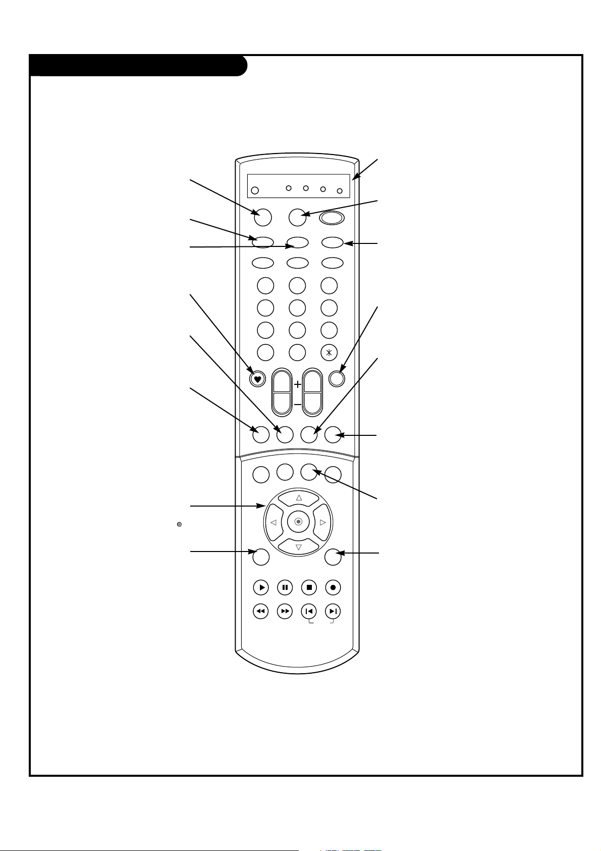
Remote Control Functions in TV Mode
1 2 3
4 5 6
7 8 9
0
tv
mode
light
power
tv/video
sleep
auto conv
vcr
cable
dvd
sat
fcr
swappipch- pipch+
pip
position
recordstop
pause
rew
play
ff
menu exit
right
enter
left
down
up
pip input video
audio
vol
ch
mute
ccarc
comp
skip
flashbk
MUTE
Switch the sound on or off
MENU
Brings up the main menu
to the screen.
EXIT
Clears all on-screen displays
and returns to TV viewing
from any menu.
VIDEO
Adjusts the factory preset pic-
ture according to the room.
PIPCH+
Changes to next higher PIP
channel.
SWAP
Swap the signal from your
PIP window to the main
screen.
FCR (Favorite Channel)
Scrolls the Favorite channel list.
THUMBSTICK
Allows you to navigate the on-screen
menus and to adjust the system set-
tings and preferences, by moving to
an option with
F G
and selecting the
highlighted option with .
TV/VIDEO
Selects: Video 1, Video 2, Video 3,
Component 1, and Component 2
input sources.
MODE
Selects the remote operating mode:
TV, VCR, Cable, DVD and Satellite.
Select other operating modes, for
the remote to control external
devices.
COMPONENT
Selects component signal sources,
such as DVD or HD receiver.
SLEEP
Set the sleep timer.
PIPCH-
Changes to next lower
PIP channel
PIP
Toggles between PIP, POP
(Picture-out-of-Picture) and
Twin picture mode.
LIGHT
Illuminates the remote control
keys.
INDICATOR LIGHTS
Show active remote mode
every time any button is
pressed.
D
E
PAGE 17
206-03865
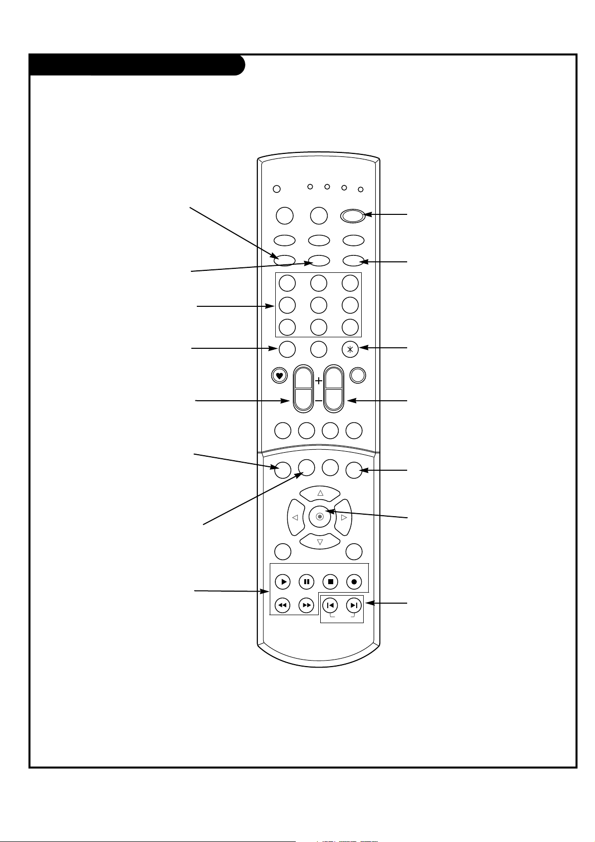
Remote Control Functions in TV Mode
1 2 3
4 5 6
7 8 9
0
tv
mode
light
power
tv/video
sleep
auto conv
vcr
cable
dvd
sat
fcr
swappipch- pipch+
pip
position
recordstop
pause
rew
play
ff
menu exit
right
enter
left
down
up
pip input video
audio
vol
ch
mute
ccarc
comp
skip
flashbk
POWER
Turns your TV or any other
programmed equipment on or
off, depending on mode.
CHANNEL UP/DOWN
Scrolls through available chan-
nels in EZ Scan memory.
NUMBER KEYPAD
For direct channel selection and
programming functions.
ENTER
When in the menu system and
other on-screen displays,
selects highlighted options.
RECORD, PAUSE, REW, FFWD,
PLAY, STOP
Control the functions on your VCR.
VOLUME UP/DOWN
Increases/decreases the sound level.
POSITION
Changes the sub picture
position.
SKIP
Playing CDs: Selects songs.
Playing DVDs: Selects movie
chapters.
ARC
(Aspect Ratio Control)
Changes the screen format or
aspect ratio.
CAPTION
Selects the caption mode.
FLASHBK
Tunes to the last channel viewed.
Not functional
PIP INPUT
Selects the input source for
the sub picture.
AUDIO
Selects the sound appropriate to
your viewing program character.
AUTO CONVERGENCE
Adjusts the picture color conver-
gence.
PAGE 18
206-03865
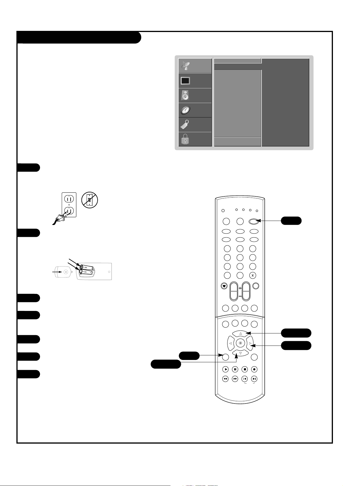
EZ Scan
Use pages 9-13 to connect external
equipment to your TV. If you have not
done so, plug in your TV to a standard
120V 60Hz power outlet.
If you have not done so, remove the back
of the remote and put in two AA batter-
ies. Make sure batteries are properly
installed (check the +/– symbols).
With the remote control in hand, press
the POWER button to turn on your TV.
Press the MENU button on the remote
control, then use the UP/DOWN arrow
button to select the Setup menu.
Press the RIGHT arrow button to access
the Setup menu.
Use the UP/DOWN arrow button to select
EZ Scan.
Press the RIGHT arrow to start the EZ
Scan channel search.
1
2
3
4
5
Automatically finds all channels available through anten-
na or cable inputs, and stores them in memory on the
channel list.
back of
remote
6
7
EZ Scan
G
CH. Edit
Fine
F Back Next G
To start
SETUP
SETUP
VIDEO
VIDEO
AUDIO
AUDIO
TIME
TIME
LOCK
LOCK
SPECIAL
SPECIAL
1 2 3
4 5 6
7 8 9
0
tv
mode
light
power
tv/video
sleep
auto conv
vcr
cable
dvd
sat
fcr
swappipch- pipch+
pip
position
recordstop
pause
rew
play
ff
menu exit
right
enter
left
down
up
pip input video
audio
vol
ch
mute
ccarc
comp
skip
flashbk
4/6
5/7
4
3
4/6
 Loading...