


SY3588
Zenith SY3588, PVY4665, PVY5265, SY3288, PVY5270 Operating Manual & Warranty
...
THE QUALITY GOES IN BEFORETHE NAME COES ON
Return the
Product
Registration
Card and your
TV could be
FR££X
/cledpaper
50percent

SAFETY WARNINGS
A
WARNING
WARNING:
TO REDUCE THE RISK OF ELECTRIC SHOCK DO NOT REMOVE
COVER (OR BACK). NO USER SERVICEABLE PARTS INSIDE.
REFER TO QUALIFIED SERVICE PERSONNEL.
TO PREVENT HRE OR SHOCK HAZARDS, DO NOT EXPOSE THIS
PRODUCT TO RAIN OR MOISTURE.
A
The lightning flash with arrowhead symbol, within an equilateral triangle,
is intended to alert the user to the presence of uninsulated "dzngerous
voltage" within the product's enclosure that may be of safficient
magnitude to constitute a risk of electric shock to persons.
The exclamation point within an equilateral triangle is intendeAito alert
the user to the presence of important operating and maintenance
(servicing) instructions in the literature accompanying the appli_aace.
POWER-CORD POLARIZATION
This product is equipped with a three-wire grounding-type
alternating-current line plug. _Ilaisplug will fit into the power
outlet only one way. This is a ,safety feature. If you are unable
to insert the plug fully into the power outlet, contact your elec-
trician to replace your obsolete outlet. Do not defeat the safety
purpose of the three-wire grounding-type plug.
CAUTION
To prevent electric shock, do rLotuse this three-wire,
grounding-type plug with an e_tension cord, receptacle or
other outlet unless all three of the blades of theeplug can be
fully inserted to prevent blade exposure.
REGULA TORY INFORMATiON
Note: This equipment has been tested and found to comply
with the limits for a Class B digital device, pursuant to Part 15
of the FCC Rules. These limits are designed to provide reason-
able protecti,on against harmful interference in a residential in-
stallation. This equipment generates, uses and can radiate
radio frequency energy and, if not installed and used in accord-
ance with the instructions, may cause harmful interference to
radio comdaunications. However, there is no guarantee that in-
terference will not occur in a particular installation. If this
equipment does cause harmful interference to radio or televi-
sion reception, which can be determined by turning the equip-
ment off and on, the user is encouraged to try to correct the
interference by one or more of the following measures:
• Reorient or relocate the receiving antenna.
• Increase the separation between the equipment and receiver.
• Connect the equipment into an outlet on a circuit different
from that to which the receiver is connected.
• Consult the dealer or an experienced radio/TV technician for
help.
CAUTION
Do not attempt to modify this product in any way without writ-
ten authorization from the manufacturer. Unauthorized modifi-
cation could void the user's atthority to operate this product.
CAUTION
These servicing instruction.,; are for use by qualified service
personnel only. To reduce 1:herisk of electric, shock, do not
perform any servicing other than those contai:ned in the operat-
ing instructions unless you arc:qualified to do so. Refer all
servicing to qualified perso:anel.
Yc'gWRNZ2
Copyright (_ Zenith Electronics Corporation 1996
ii
IMPORTANT SAFETY INSTRUCTIONS
Your product has been manufactured and tested with your safety in mind. However, improper use can result in potential electrical
shock or fire hazards. To avoid defeating the safeguards that have been built into your new product, please read and observe the
following safety points when installing and using your new product, and save them for future reference.
Observing the :simple precautions discussed in this section of the operating guide can help you get many years of enjoyment and
safe operation that are built into your new product.
1. Read Instructions
All the safety and operating instructions should be
read before the product i:_operated.
2. Follow Instructions
All operating and use instructions should be fol-
lowed.
3. Retain Instructions
The safety and operating instructions should be re-
tained for future reference.
4. Heed Warnings
All warnings on the product and in the operating in-
structions should be adhered to.
5. Cleaning;
Unplug this product from the wall outlet before
cleaning. Do not use liquid cleaners or aerosol
cleaners. Use a damp cloth for cleaning.
6. Water and Moisture
Do not use this product near water -- for example,
near a bath tub, wash bowl, kitchen sink, or laundry
tub, in a wet basement, or near a swimming pool.
7. Accessories
Do not place this product on an unstable cart,
stand, tripod, bracket, or table. The product may
fall, causing serious injury to a child or adult, and
serious damage to the product. Use only with a
cart, stand, tripod, bracket, or table recommended
by the manufacturer, or sold with the product. Any
mounting of the product should follow the manufac-
turer's instructions, and should use a mounting
accessory recommended by the manufacturer.
8. Transporting Product
A prod_act and cart combination should be moved
with care. Quick stops, excessive force, and uneven
surfaces may cause the product and cart combina-
tion to overturn.
PORTABLE CART WARNING
9. Attachments
Do not use attachments rLotrecommended by the
product manufacturer as they may cause hazards.
10. Ventilation
Slots and openings in the cabinet are provided for
ventilation and to ensure reliable operation of the
product and to protect it from overheating, and
these openings must not be blocked or covered. The
openings should never be blocked by placing the
product on a bed, sofa, rag, or other similar sur-
face. This; product should not be placed in a built-in
installation such as a bookcase or rack unless
proper ventilation is provided or the manufacturer's
instructions have been adhered to.
11. Power Sources
This product should be c,perated only from the type
of power source indicated on the marking label. If
you are not sure of the: type of power supply to
your home, consult your product deali_r or local
power company. For lzroducts intended to operate
from baltery power, or other sources, refer to the
operating instructions
12. Line-Cord Polarization
This product is equipped with a polarized alternat-
ing-current line plug (a plug having one blade
wider than the other). This plug will fit into the
power outlet only one way. This is a safety feature.
If you are unable to insert the plug fully into the
outlet, try reversing the plug. If the p!Lugshould
still fail Io fit, contact your electrician to replace
your obsolete outlet. Do not defeat the safety pur-
pose of the polarized phxg.
13. Power-Cord Protectio_L
Power-supply cords shoJld be routed so that they
are not likely to be walked on or pinched by items
placed upon or against them, paying particular at-
tention to cords at plugs, convenience receptacles,
and the point where they exit from the product.
°o,
¥SAFEI Ul

m
IMPORTANT SAFETY INSTRUCTIONS
1,1. Outdoor Antenna Grounding 18.
If an outside antenna or cable system is connected
to the product, be sure the antenna or cable system
is grounded so as to provide some protection
against voltage surges and built-up static charges.
Article 8!0 of the National Electrical Code
(U.S.A.), ANSI/NFPA 70 provides information 19.
with regard to proper grounding of the mast and
supporting structure, grounding of the lead-in wire
to an antenna discharge unit, size of grounding con-
ductors, location of antenna-discharge unit,
conneclien to grounding electrodes, and require- 20.
ments for the grounding electrode.
EXAMPLE OF GROUNDING ACCORDING TO
NATIONAL ELECTRICAL CODE INSTRUCTIONS
Antenna Lead in Wire
Ground
,_ Antenna Discharge Unit
_---------.---._._ J/ (NEC Section 810-20)
I _ _ Grounding Conductors
. (NEC Section 810-21)
Power Service Grounding
Electrode System (NEC
T Art 250, Part H)
NFC - NATIONAL [-LECTRICAL CODE
15. Lightning
For added protection for this product (receiver) dur-
ing a lightning storm, or when it is left unattended
and unused for long periods of time, unplug it from
the wall outlet and disconnect the antenna or cable
system. This will prevent damage to the product
due to lightning and power-line surges.
1,6. Power Lines
An outside antenna system should not be located in
the vicinity of overhead power lines or other elec-
tric light or power circuits, or where it can fall into
such power lines or circuits. When installing an out-
side antenna system, extreme care should be taken
to keep from touching such power lines or circuits
as contact with them might be fatal.
17. Overloading
Do not overload wall outlets and extension cords as
this can result in a risk of fire or electric shock.
Object and Liquid Entry
Never push objects of any kind into this product
through openings as they may touch dangerous volt-
age points or short-out parts that could result in a
fire or electric shock. Never spill liquid of any kind
on the product.
Servicing
Do not attempt to service this product yourself as
opening or removing covers may expose you to dan-
gerous voltage or other hazards. Refer all servicing
to qualifie.d service personnel.
Damage Requiring Service
Unplug this product from the wall outlet and refer
servicing to qualified service personnel under the
following conditions:
a. If the power-supply cord or plug is damaged.
b. If liquid has been spilled, or objects have fallen
into the product.
c. If the: product has been exposed to rain or water.
d. If the product does not operate normally by fol-
lowing the operating instructions. ,Adjust only
those controls that are covered by the operating
instructions as an improper adjustment of other
controls may result ir_ damage and will often re-
quire extensive work by a qualified technician
to restore the product to its normal operation.
e. If the: product has been dropped or the cabinet
has been damaged.
f. If the product exhibits a distinct change in per-
formance.
21. Replacement Parts
When replacement parts .are required, be sure the
service technician has used replacement parts speci-
fied by the manufacturer or have the same
characteristics as the original part. Unauthorized
substitutions may result in fire, electric shock, or
other hazards.
22. Safety Check
Upon completion of any service or repairs to this
product, ask the service technician to perform
safety checks to determine that the product is in
proper operating condition.
23. Wall or Ceiling Mounti:ag
The product should be mounted to a wall or ceiling
only as recommended by the manufacturer.
24. Heat
The product should be shuated away from heat
sources such as radiators, heat registers, stoves, or
other products (including: amplifiers) that produce
heat.
YSAFEI iv
m
INTRODUCTION
WELCOME
Welcome into the family of Zenith Color Television owners.
"ibis guide provides instructions on how to operate your new
T_. In addition, we strongly advise you to read and observe
the precautions listed in the Safety Tips section of this operat-
ing guide. Read this publication carefully so that you will re-
ceive full enjoyment from your new Zenith TV for many years
to come.
Your new TV has been designext and built to give you the very
best in quality,, features and pertormance. There are many re-
gional Zenith authorized service: centers throughout the U.S.,
Canada and Mexico who can at|end promptly and effectively
to ordinary service needs.
If you should have an unusual performance or service problem
that cannot be ,,;atisfactorily resolved by your Zenith authorized
service center, call or write:
Zenith Electronics Corporation
Customer Service Department
1000 Milwaukee Avenue
Glenview, IL 6C_325-2493
Telephone: (847) 391-8752
Mon-Fri, 8:00 a.m. - 4:30 p.m. Central Time
Send the model[ number, serial number, and dale of purchase
or original installation, with a full explanation of the problem
and the service history. We will welcome the opportunity to
look into your :specific question or problem and to be of assis-
tance in resolving it promptly.
The model and serial numbers of your new TV a_:elocated on the
back of the TV cabinet. For your future convenience and protec-
tion, we suggest that you record these numbers here:
Model No.
Serial No.
INSTALLATION CONSIDERA"I IONS
Before you install your TV...
Ventilation -- Proper ventilation keeps your TV
running cool. Air circulates through perforations
in the back and bottom of the cabinet. Do not
block these vents or you will shorten the life of
your "IV.
Power Source -- Your TV is designed to operate
on normal household current, 120 volt 60 Hertz AC.
Do not attempt to operate it on DC current.
Power Cord -- Your power cord has a polarized
plug as required by Underwriters' Laboratories. It
has one regular blade and one wide blade and fits
only one way into a standard electrical outlet. If
the blades will not enter either way, your outlet is
w;ry old and non-standard. A new outlet should be
installed by a qualified electrician.
Safe Operation -- Your TV is manufactured and
tested with your safety in mind. However, unusual
stress caused by dropping or mishandling, expo-
sure to flood, fire, rain or moisture, or accidental
spilling of liquids into the TV, can result in poten-
tial electrical shock or fire hazards. If this hap-
pens, have your TV checked by a service
technician before using it again.
Please read and observe each safety point in the "Safety
Tips" section when installing and using your TV.
VIDEO GAMES AND OTtlER FIXED
PATTERN DISPLAY CAUT]ION -- If you use your TV for
video games or other fixed disp lays, avoid setting the
BRIGHTNESS control for an excessively bright picture. A
fixed display L';any image which does not change frequently,
such as a channel/network identification or other symbol that
remains in the same location for long periods of time. A
bright, fixed pattern, if left on for long periods of time, can re-
sult in a permanent imprint oa tae "IV picture tube. You can re-
duce this possibility by alternating the use of the fixed pattern
display with normal TV pictrxe viewing, by turning down the
CONTRAST control for sustaired fixed pattern use, and by
turning off the fixed pattern display when not in use.
PLUGGING IN YOUR TV --- Be sure to plug your TV into
an "unswitched" AC power source. The "switched" AC out-
lets found on some video equipment will not continue supply-
ing power to the TV once the extuipment is turned off. If the
power to the TV is interrupted, you will have to reset the clock
in the TV to the current time.
TVWELDIR3 V

INTRODUCTION
m
METHODS OF 71t' AND ACCESSORY EQUIPMENT OPERATION
Y_ur new Zenith TV is a very sophisticated, High-Tech electronic appliance. "IV operation, video pictare adjustments and audio
sound adjustments are performed through on-screen menus and displays. Self-explanatory menu icons are used throughout. Most
features can be selected and adjusted from the comfort of your favorite chair by using either of the infrared remote controls, the Uni-
w_rsal (7 Mode) remote or the Z-Trak trackball (TV/VCR) remote. Either of the two remote control:_ can be used to operate the TV.
Use the multi-brand (7 Mode) programmable remote if you have different brands and[types of equipment in your video system
which you need to control remotely. Use the Z-Trak (TV/VCR) programmable remote if you feel comfortable using trackball access
similar to that provided by the familiar computer mouse device. Also, many features can be selected and adjusted by using the con-
trol panel on the TV, except for StarSight.
StarSight provides an electronic programming guide which is updated with new scheduling information automatically while the TV
is Off. StarSight allows you to rapidly scan through the channel programming guide to find a prograna for viewing oi recording. Pro-
g_:amscan be searched and selected by category, theme, subject, etc. if desired.
FEATURES PROVIDED ON YOUR TV
This operating guide describes a family of TV models. Not all models have all of the features described in this guide. In addition,
different control panels may be used from model to model. Most models include the following features:
GENERAL FEATURES
Optional StarSight ® Program Guide Capability
Automatic TV Operation Demonstration
On-Screen Menus accessed by Remote Controls or TV Con-
trol Panel
Universal (7 Mode) Programmable Remote Control
Z-Trak Trackball (TV/VCR Modes) Programmable
Remote Control
Closed Captions and Text Modes
l81 Channel Tuning
Automatic Channel Search Programming
Parental Control, Block Channel(s)
Channel Labels (ABC, NBC, MAX, SHO, etc.
or create your own custom labels)
Source Identif-lcation (VCR, Cable Box, etc.)
Sleep Timer
On/Off Timer (Vacation Timer)
Activate/Deactivate On/Off Timer selection
On-Screen _-ognIdentifiers
Antenna/Cable and Loop-Out to Cable Box Jacks
Rear Chassis In/Out Audio/Video (A/V) Jacks
AUDIO FFATURES
2-Level Audio Mute Control
On-Screen Captions when Audio Muted
Variable Audio Output jacks
External Surround Sound Speaker',s) Output Jacks
Front and Rear Surround Sound Speaker Contro]Ls
Preset Surround Sound
Surround Sound Speaker Hook-Up Jacks
On-Screen Audio Adjustments
MTS Stereo
SoundRite Auto Volume Control
PIP (Picture-In-Picture) FEATURES
Video Swap PIP Window/Main Screen Picture
PIP/Main Screen Pictures Freeze
Picture-In-Picture Capability wi.th2 Direct-Source TV Tuners
1-Minute Commercial Break Surf.-to-PIP Channel Scanning
Audio Swap PIP Window/Main S:reen Picture
Move PIP Window anywhere on-screen
with Z-Trak Remote
Front Chassis In Audio/Video (A/V) Jacks Channel Surf-to-PIP
(Available on some models Olfly)
On-Screen Video Adjustments ADDITIONAL PROJECTION TV ONLY FEATURES
Channel Scan Add Channels VCR Shelf
Channel Scan Delete Channels Built-in Screen Protector (Avai!Lalzleon Some Models)
Select Channel Surfing Channels Optional Screen Protector (Available on Some Models)
Z-Trak Icons Menu Larger TV/Source Connections Jack Panel on back of TV
Adjustable Pointer Speed Control for Trackball Remote iFront Video/S-Viideo Input Jacks
3_63-o vi

CONTENTS
Connections and Basic Operations
Safety Warnings ...................................... ii
hnportant Safety Instructions ............................ iii
INTRODUCTION
Welcome ............................................ v
Installation Considerations .............................. v
Methods of Operation .................................. vi
Features Provided on your TV Chart ...................... vi
Setup Checklisl ...................................... viii
STANDARD TV/SOURCE CONNECTIONS
Introduction TV/Source Connection Panel, Overview Connection
Options, TV/Source Connections Panel, Front ofTV A/V Jacks,
Setups: I-TV Only, 2-TV and Cable Box, 3-TV and 4-VCR, TV
_ith VCR and Cable Box, Accessory Jacks, Surround
Speakers and Audio Amplifier .......................... 1-1
FIRST TIME YOU OPERATE YOUR TV
Control Panel, Battery Installation, Power, Main Picture and PIP
Source, Auto Program, Clock, Other Options and Projection TV
Setup .............................................. 2-1
PIP (Picture-in-Picture) OPERATION
Overview, Selecting Main Picture and PIP Inset
Source, PIP ON/Off, PIP Features/Controls Options with
Universal and Trackball remotes, PIP Source Capabilities with
Different Connection Setups ........................... 3-1
(Jniversal Remote Control Menus
UNIVERSAL REMOTE CONTROL MBR3459
Introduction, Battery Installation, Operating Mode, TV
Operations, Key Functions Chart, Programming,
Special Features, Auto Find, and Brand Codes ............. 4-I
QUICK REFERENCE TO MENUS
Available Menus, Basic Menu Operation ................. 5-1
SOURCE MENU
Menu Operation, Source Selection ....................... 6-1
SETUP MENU
Menu Operation, Auto Program, Channel Add/Del/Surf, Clock
Set, Captions, Caption/Text, Language, Background, StarSight
Projo Setup: Color Convergence ........................ 7-1
SPECIAL FEATURES
Menu Operation, Timer Setup, Sleep Timer, On/OffTimer,
Channel Labels, Source ID, Parental Control, Auto Demo .... 8-1
AUDIO MENU
Menu Operaffon, Bass, Treble, Balance, Audio Mode, SoundRite,
F:ont Surround Rear Surround, Speakers ................. 9-I
VIDEO MENU
Contrast, Brightness, Color, Tint, Sharpness, Color
Temp, Video Filter, Skin Tone, and Video Preset .......... 10-I
PIP VIDEO I_IENU
Contrast, Tint, Size ................................... 11-I
Z-Trak Remote Control Menus
Z-TRAK TRACKBALL REMOTE CONTROL
Introduction, Battery Installation, Choosing Operating Mode,
Basic Operations, VCR Function Keys, Auto Find, VCR Brand
Codes, Cleaning: the Trackball ........................ 12-1
Z-TRAK REMOTE MENUS OVERVIEW
Available On-Screen Menus, Basic Menu Operation,
Menu Icons, On-Screen Displays, Volume Control ......... 13-1
Z-TRAK REMOTE MENU OPERATION
Point and Press Operation, Menu Operation Options ....... 14-1
Z-TRAK REMOTE SOURCE MENU
Menu Operation, Source Selection ...................... 15-1
Z-TRAK REMOTE SETUP MENU
Menu Operation, Auto Program, Channel Add/Del/Surf, Clock
Set, Captions, Caption/Text, Language, Background,
StarSight .......................................... 16-1
Z-TRAK REMOTE SPECIAL FEATURES
Menu Operation, Timer Setup, Sleep Timer, OrdOff Timer,
Channel Labels, Source ID, Parental Control, Auto Demo... 17-1
Z-TRAK REMOTE AUDIO MENU
Menu Operation, Bass, Treble, Balance, Audio Mode, SoundRite,
Front Surround, Rear Surround, Speakers ................ 18-1
Z-TRAK REMOTE VIDEO MENU
Menu Operation, Contrast, Brightness, Color, Tint, Sharpness,
Color Temp, Video Filter, Skin Tone, and Video Preset ..... 19-1
Z-TRAK REMOTE PIP VIDEO MENU
Menu Operation, Contrast, Tint, Size .................... 20-1
Maintenance and _Varranty
MAINTENANCE AND TROUBLESHOOTING
Caring, Extended Absence, Interference,
Before Calling for Service ............................ 21-1
Recommended Accessories
Replacement Product Registration Card
Your Zenith Warranty
tlow to use this operating guide
Standard TV installation and operation is given in this portion of the operating guide. Follow the procedures given if you will not
be using StarSight®. Two remote controls are provided, each with its own set of on-screen menus. Refer to the appropriate sec-
ti3ns of this guide when using the different remote controls.
,i_ Refer to the StarSight® portion of this operating guide for StarSight® activation and ope:ration.
3(1'53-O vii
SETUP CHECKLIST
_ ote: Turn off the power on all system components before making connections. Do not disconnect your cable box power
, cord, it may interfere with your cable service.
3 Connect All Source Equipment to TV
E3
[3
E3
[-1
[3
[3
[3
Connect your Antenna or Cable service line as well as any accessory equipment such as a V('R. Do not connect this TV or
other system component equipment to an electrical outlet that is controlled by a wall switch.
Install Batteries in the Remote Controls
Batteries are provided but must be installed in both the universal and trackball remote controls.
Turn on All Source System Components
The TV and other Source equipment you connected to the TV/Source Connection Panel or, if available, the "I_/"Front Panel.
Select Main Picture Source and PIP Inset Picture Source
The IMam Picture Source and the PIP Inset Window Picture Source can be any source listed anc available in the Source Menu.
Subscribe to StarSight Service (Optional)
You do not have to subscribe to StarSight to operate this TV.
Refer to the StarSight portion of the operating guide for StarSight subscription information.
Perform Projection TV Setup (Projection TV Models Color Convergence)
This procedure should be performed when the TV is first installed and if it is moved later to a different location.
Perform Auto Program Procedure (Not required with StarSight Service)
This procedure finds and stores the available channels from your local broadcast area in the TV's memory.
Options
You may consider using the following options: Surf Channel Scan, Channel Labels, Channel Add/Delete/Surf_ Source ID, and
make changes to the Audio and Video settings to your personal preference.
Two Tuner Capability
Using either Ant/Cable 1or 2 sources gives you two-tuner capability; one Tuner for the Main Picture, and a second Tuner for the
PIP Inset Picture. (Use the TV to tune 2 live TV channels, depending on hookup.)
Options Quick Overview
Surf Channel Scan -- Create a list of only the channels you view frequently for access by Chan Up/Down.
Channel Labels -- Include a channel or network name such as HBO, Max etc., for the channels you receive or give a channel a cus-
tom name of your own.
Channel Add/Delete/Surf-- Allows to you include or omit any available channel from the channel scan accessed by Chan
Up/Down.
1-Minute Commercial Surf-to-PIP -- Allows you to transfer temporarily your surf channels to the Main screen picture for viewing
while a commercial is being broadcast.
Source ID -- Allows you to label and identify your system component by type of equipment such as VCR, Photo CD, etc.,
Audio/Video Adjustments -- You can set the video and audio adjustments to your personal preferences.
Color Conver£ence -- Projection TVs only. Aligning Red and Blue colors over Yellow yields the ultimate in picture appearance.
"]?hereare some TV models that have built-in and optional screen protectors, be sure to follow instrnJclions when cleaning them be-
comes necessary.
..o
3363-0 VIII

STANDARD TV/SOURCE CONNECTIONS
INTRODUCTION W/SOURCE CONNECTION PANEL
Shown below are examples of the type of "Source" equipment you can connect to your TV. Your antenna or cable service line
should be connected to Antenna/Cable 1. If you have a Cable Box, connect it to Antenna/Cable 2. Use the Audio/Video connections
for accessory equipment like a VCR. To hear stereo audio from your stereo VCR during tape playback, you must use the
Audio/Video connections. Note: Additional Audio/Video Input jacks are provided (on some TVs) on the front of the TV for your
convenience.
OVERVIEW: SOURCE EQUIPMENT CONNECTION OPTIONS
Over-the-Air Antenna
or Cable Service
®
/
Input Source jacks on TV/Source Connection Panel
on back of TV and A/V inputs on front.
Antenna/Cable 1 In Jack
Antenna/Cable 2 In Jack
Video 1In Jacks
Video 2 In Jacks
S-Video In Jacks
l:¥ont Audio/Video (In) Jacks
Camcorder
L TV,Source
Connection -_--__ _____aye_'/ J
Panel __
Output Jacks on TV/Souv'ce Connections Panel to
Accessory Equipment
Loop-Out to Cable Box
Monitor Out Jacks
Variable Audio Out Jacks
Surround Speakers Out Jacks
External Speakers Out Jacks
StarSight Emitter Output Jack
Speaker On/Off Switch
Speaker Internal/External Switch
Example list of accessory equipment that can be
connected to the TV/Sourc,.=Connections Panel and
front of TV.
VCRs, S-Video Equipment, Camcorders, Lase:r Video Disk
Players, Video!Surveillance Cameras, Various Audio Equip-
ment such as an Audio Amplifier or Stereo System, External
Speaker, Surround Sound Speakers etc. Use Audio/Video Ca-
bles to make the connections sh,gwn above.
Note: Cables shown above are not supplied with your TV and
can be purchased at your local Zenith dealer. Measure each ca-
ble length nee_ted.
3,_63-o 1 -- 1

STANDARD W/SOURCE CONNECTIONS
I I
TV/SOURCE CONNECTIONS PANEL
Locate the TV/Source Connection Panel on the back of the TV.
ANTENNA/CABLE 1
75-ohm antenna or cable-TV con-
nection to your TV. Attach your an-
tenna, cable-TV line or VCR to
this jack.
ANTENNA/CABLE
Routes the cable-TV input to
Antenna/Cable 2 back to the cable s_oEoj_ ,o---_'-
box supplied by the cable service. @ _)-)_,_--_ _
SPEAKER EXT/INT
Select EXT (external) to remove _ -_
, -_ ,,
sound from the TV s speakers. __ O ® _st_._ _ONtToff_,,-72----
•
Select INT (internal) to, hear sound _ _N _ _ _) (.3__
from the TV s speakers, c0_0t _T _ _
SURROUND SPEAKER __ _ ,,,_,_
TERMINALS __ __
Connections for output to optional _
surround sound speakers.
VII)EO 1 or 2 IN
Jacks for audio and video input
_ from a stereo VCR or other A/V
c,aw,ponent. (You must connect to
these jacks in order to hear stereo
sound when playing a stereo tape.)
S-VIDEO IN
-- Jacks for audio and video input
f:rora a Super-VHS component.
MONITOR OUT
Standard audio/video jacks for out-
put to an audio/video monitor.
VARIABLE AUDIO OUTPUT
Standard phono jack connectors for
output to an optional stereo ampli-
fier or to external speakers•
TURN OFF POWER OR UNPLUG
TV POWER CORD BEFORE
MAKING ANY CONNECTIONS.
STARSIGHT CONTROL PORT
Jack for connection of StarSight Re-
mote Emitter cable•
FRONT CHASSIS W/SOURCE CONNECTIONS PANEL, (Availabte on Some Models)
If your TV model is equipped with front TV/Source A/V input jacks, they are located behind a small door on the control panel on
• e front of the TV. Although two types of panels are used on the front of the TV (as shown below), in the on-screen menus, both
Type I and Type 2 are referred to as "Front Video" and "Front S-Video."
Note: Use the Right and Left Audio jacks with either Video or S-Video jacks.
Type I, S-VIDEO (In)
Jacks for audio and video input from a Super-VHS VCR.
Type II, S-VIDEO 2 (In)
Jacks for audio and video input from a Super-VHS VCR.
S-VIDEO VIDEO
FRONT VIDEO INPUT
RIGHT LEFT
_ FRONT AUDIO INPUT-
S-VIDEC) 2 VIDEO 3
VIDEO INPUT
RIGHT
AUDIOINPUT
I_pe I, VIDEO (In)
Jacks for audio and video input from a stereo VCR or other A/V
component.
Type II, VIDEO 3 (In)
Jacks for audio and video input from a stereo VCR or other A/V
component.
3')63-O 1 _ 2

I
STANDARD W/SOURCE CONNECTIONS
SETUP 1: TV ONLY
If'you receive your television signal by antenna or basic cable-
TV (no cable box), connect your television as shown here.
TURN OFF POWER OR UNPLUG TV BE-
FORE MAKING ANY CONNECTIONS TO
YOUR TV.
;able Leading from.. Connected to..
Wall Jack--- TV--
5 ohm Antenna From Antenna or "Antenna/Cable
?able Cable Service. I."
Note: All cables shown are not supplied with this TV.
Antenna or Cable.-TV Connection
SETUP 2: TV AND CABLE BOX
If you receive your television signal from a cable box,
connect your television as shown in the illustration.
DO NOT UNPLUG YOUR CABLE BOX
POWER CORD Ar ANY TIME!
, DO NOT PLUG YOUR TV POWER CORD INTO
TIlE BACK OF YOUR CABLE BOX!
'able
5 ohm Antenna
_able
5 ohm Antenna
:able
5 ohm Antenna
?able *
) (Supplied)
',emote Emitter
;able.
Leading from..
Wall Jack--
From Antenna or
Cable Service.
TV--
"Loop Out To
Decoder."
Cable Box--
"Out."
Connected to..
TV--
"Antenna/Cable
2."
Cable Box---
"In."
'IV m
"Antenna/Cable
1."
TV-- Cable Box---
"StarSight Control Front panel.
Port."
Note: All cables shown are not supplied with this TV.
Cable Box Connection
CABLE BOX
FRONT
StarSight Note: Do not adhere the Remote Emitter until af-
t_w you have completed activating StarSight and you have
confirmed the correct code that operates your Cable Box.
Once the code is confirmed, peer off the backing of the sticker
on the Remote Emitter and adhere it in place.
If you want to activate StarSight, proceed to the StarSight sec-
tion of the operating guide.
Note: Cables shown above can be purchased at your local Ze-
nith dealer. Measure each cable !,ength needed.
;uo.,a. gto]
activate StarSight.
3<:63-0 1 -- 3
l
STANDARD TV/SOURCE CONNECTIONS
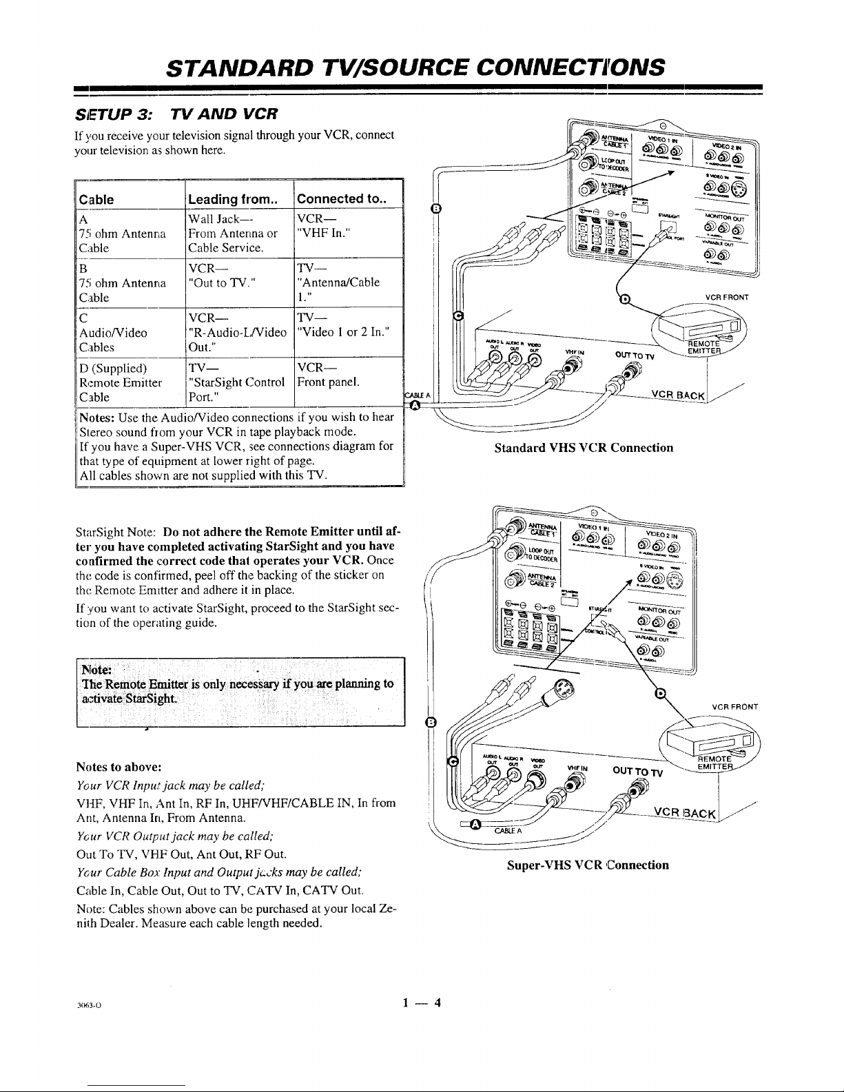
SETUP 3: TV AND VCR
If you receive your television signal through your VCR, connect
your television as shown here.
Cable
A
7-<;ohm Antenna
Cable
B
7,'; ohm Antenna
Cable
C
Audio/Video
Cables
D (Supplied)
Remote Emitter
Cable
Leading from..
Wall Jack---
From Antenna or
Cable Service.
VCR--
"Out to TV."
VCR--
"R-Audio-L/Video
Out."
TV--
"StarSight Control
Port."
Connected to..
VCR--
"VHF In."
TW--
"Antenna/Cable
1 ."
TV--
"Video I or 2 In."
VCR--
Front panel.
Notes: Use the Audio/Video connections if you wish to hear
iStereo sound flom your VCR in tape playback mode.
If you have a Super-VHS VCR, see connections diagram for
that type of equipment at lower right of page.
All cables shown are not supplied with this TV.
0 _ [_ _ __ ._----_
!_J,_ _ I_l I_ _1,..,.x._ "_ __
il _--_J" _-_---___._ _--:_
Standard VHS VCR Connection
StarSight Note: Do not adhere the Remote Emitter until af-
ter you have completed activating StarSight and you have
confirmed the correct code that operates your VCR. Once
the code is confirmed, peel off the backing of the sticker on
the Remote Emitter and adhere it in place.
If you want to activate StarSight, proceed to the StarSight sec-
tion of the operating guide.
Notes to above:
Y_ur VCR lnpu_t jack may be called,"
VHF, VHF In, Ant In, RF In, UHF/VHF/CABLE IN, In from
Ant, Antenna In, From Antenna.
Ycur VCR Output jack may be called;
Out To TV, VHF Out, Ant Out, RF Out.
Your Cable Boa: Input and Output jc:cks may be called;
Cable In, Cable Out, Out to TV, CATV In, CATV Out.
Note: Cables shown above can be purchased at your local Ze-
nith Dealer. Measure each cable length needed.
Super-VHS VC R ,Connection
3(r63-0 1 -- 4

STANDARD TV/SOURCE CONNECTIONS
SETUP 4:" TV WITH VCR AND CABLE BOX
I1:you receive 5'our television signal through your Cable Box and
VCR, connect your television as shown here.
DO NOT UNPLUG YOUR CABLE
BOX POWER CORD AT ANY TIME!
DO NOT PLUG YOUR TV POWER CORD
INTO THE BACK OF YOUR CABLE BOX!
;able Leading from.. Connected to..
Wall Jack--- TV--
'5 ohm Antenna From Antenna or "Antenna/Cable
7able Cable Service. 2."
TV-- Cable Box--
'5 ohm Anterma "Loop Out to "In."
".able Decoder."
Cable Box-- VCR--
'5 ohm Antenna "Out." "VHF In."
_able
) VCR-- TV--
'5 ohm Antenna "Out To TV." "Antenna/Cable
.'able 1."
VCR-- TV--
_udio/Video "R-Audio-L/Video "Video 1 or 2 In."
2ables Out."
(Supplied) TV-- VCR/Cable Box--
remote Emitler "StarSight Control Front Panels.
:able Port."
Notes: Use the Audio/Video connections if you wish to hear
Stereo sound from your VCR in tape playback mode.
StarSight Note: Do not adhere the Remote Emitters until af-
ter you have completed activating StarSight and you have
confirmed the correct codes that operate your equipment.
Once the codes are confirmed, peel off the backing of the
sticker on the Fmitters and adhere it in place.
a,
I1!you want to activate StarSight, proceed to the StarSight sec-
tion of the operating guide.
_=::::O::::= I ,
kL"-..
CABLE
// BOX
/ _'_-__ VCR
IIII _ _ _--_-_ _, FRONT
Cable Box and VC R Connection
Notes to abow;:
Your VCR Input jack may be ca;led;
VHF, VHF In, Ant In, RF In, UHF/VHF/CABLE IN, In from
Ant, Antenna In, From Antenna.
Your VCR Output jack may be called;
Out To TV, VHF Out, Ant Out, RF Out.
Your Cable Box Input and O_',tp,_tjacks may be called;
Cable In, Cable Out, Out to q-V, CATV In, CATV Out.
Note: Cables shown above can be purchased at your local Ze-
nith dealer. Measure each cable length needed.
_ivate StarSight.
3(_3-o 1 -- 5

STANDARD TV/SOURCE CONNECT IONS
I
FRONT 71/" AUDIO/VIDEO (A/V) CONNECTIONS FOR OPTIONAL VA'DEO EQUIPMENT
S,.r.oCmoo,d.,__
Connections to FRONT VIDEO IN -- I _
or FRONT S-VIDEO IN jacks. _
(Some TV models only.) ,t_,/ _,_
........
Super-VHS VCR wcwDto
O_JT
o1
i
,ll_o lmdr -_ t,t,o_ lm_R_-_
OPTIONAL AUDIO AMPLIFIER/SURROUND SOUND CONNECTIONS TO TV
If you wish to lislen to the TV audio through an external amplifier or stereo system, or listen to surround sound audio, make the connec-
tions to the TV shown in the illustration below.
,_ TURN OFF POWER OR UNPLUG TV BEFORE MAKING ANY CONNECTIONS TO YOUR TV.
Surround
:_peakers Silver _ _)_
.......
L___V Si_,_r
Amplifier and Dual Surround Speaker Connections
Sider
8 ohm
Surround
Speaker
Single Surround Sp_mker Connection
a
TV Speakers On
(Some Models Only) :
SPEAKER EXT/INT switch in the INT
(internal) position --
TV speakers are ON. Sound is heard
from both the TV's speakers and the
external amplifier's speakers.
Use TV's volume control to raise and
lower the level of sound being heard
from both sets of speakers.
TV S_ers
:(S0me Models O_y)
_3 SPEAKER EXT/INT switch in the EXT
(external) position --
TV speakers are OFF. Sound is only heard
from the speakers connected to the external
amplifier.
ta Use TV's volume control to raise and
lower the level of sound being heard from
the amplifier's speakers.
DIFFERENT WAYS TO LISTEN TO YOUR W :: : :
: :: S-,rro_dSo_d:
Q Connect :_urround sound speakers as
shown. The:level of surround sound will
vary, depending on the proglarn being
viewed. Nete that not all programs have
surround so and audio.
Q The SURROUND SPKR terminals are
always active. The SPEAKERS EXT/INT
switch does not affect the operation of
surround sound speakers.
ta If you w_mtto connect only one surround
speaker to your TV, connect the speaker
wires to the terminals adjacent to the
posigive (+) and negative (-) symbols that
are circled.
3os3-o 1 -- 6

THE FIRST TIME YOU OPERATE YOUR, TV
E1 II
TYPICAL CONTROL PANEL
The control panel on your TV may differ from the one shown but its operation is the. same.
ENTER (ENT) SELECT (SEL) VOLUME (VOL) Down/Up
Press to see the Channel/Time dis- Press during on-screen menu op- Press to dcx:rease or increase the
p'_ay,or to remove any on-screen di,;- erations to select a menu option, sound leve.1.
Viay or menu.
ENTER </_JUST• SELECT •VOLUME • •ella |NEE• POWER
/ /
POWER
Press to turn TV
power ON or OFF.
I
ADJUST (ADJ) Left/Right
Press during on-screen menu opera-
tJon to see information/status display
f3r selected option. Press again to ad-
jast the selected menu option.
MENU
Press once to see a menu. Press re-
peatedly to sequence through the
available menus.
CHANNEL (CH) Down/Up
Press to select channels lowc:r or
higher thma the current ch annel.
Remote Window
Point the remote con-
tro] towards this
window to operate the
TV.
PROJECTION TV CONTROL PANEL
_e control panel on your TV may differ from the one shown but its operation is the same.
SELECT (SEL)
Press during on-screen menu
operations to select a menu
option.
ENTER (ENT)
Press to see the Channel/Time
display, or to remove any on-
screen display or menu.
VOLUME (VOL) Up/Down
Press to increase or dex:rease the
sound level.
OFF-ON
Press to turn TV
power ON or OFF.
r
ADJUST (ADJ) Left/Right
Press during on-screen menu op-
eration to see information/status
display for selected option. Press
again to adjust the selected menu
option.
MENU
Press once to see a menu. Press
repeatedly to sequence through
the available menus.
CHANNEL (C H) Up/Down
Press to select channels higher or
lower than the current channel.
To add or delete channels stored
in the scanning sequence, see CH.
ADD/DEL option.
CONNECT THE POWER
1. Plug your TV into an unswitched AC power source.
(Normal household current outlet that is not controlled
by a wall switch.)
2. Turn the TV On by pressing POWER.
,®:¥,, ]_
Do not plug TV into switched outlet
on a VCR or cable-TV decoder
3o63-o 2- 1

I
THE FIRST TIME YOU OPERA TE YOUR TV
STEP 2. INSTALL THE BATTERIES INTO THE REMOTE CONTROLS
Batteries are provided but they must be installed before using
the remote controls. When a remote no longer functions nor-
mally, or when it loses memory, replace the batteries with
high-quality, alkaline batteries. !vlatch plus with plus (+ with
+), minus with minus (- with -), as shown in the battery com-
pamnent.
Unless your equipment responds to the factory preset codes,
you will need to reprogram the remote controls with the codes
of your particular equipment each time you replace batteries.
Universal Remote
(Uses 2 size AAA
batteries.)
Notes:
[] Do not to place heavy objects on top of the remote control
keys. Prolonged unintentional operation of the remote short-
ens batter?, life.
[] Remove the batteries if the remote control will not be used
for a month or more. aRE MANUFACTURER IS NOT RE-
SPONSIBLE FOR DAMAGE CAUSED BY BATTERY LEAKAGE.
Z-Trak Remote (
(Uses 2 size AA
batteries.)
STEP 3. SELECT YOUR MAIN SOURCE & PIP (Picture-in-Picture) SOURCI"
A TV source refers to the equipment connected to the TV/Source Connections Panel that supplies tbe picture and sound to your TV.
You select the viewing source by using the Source Menu. Use the universal remote control.
.Main Picture Source
1. Press SOURCE on
your ren_tote to view
the Source Menu.
:2.
Use Up or Down
arrow key to select the
Main Picture source
--which corresponds
to the jack(s) on the
TV/Source
Connection Panel.
:3. Press QUIT to remove
the menu.
pIP Inset Picture Source
1. Press SOURCE on
your remote to view
the Source Menu.
2. Use the Left or Right
arrow key to select
PIP Source column.
3.
Use the Up or Down
arrow key to select the
PIP Window Inset
Picture source.
4. Press QUIT to remove
the menu.
Ource
nu
Main <1, PIP
Ant/Cable 1 ]
Ant/Cable 2
Video 1
Video 2
S-Video
Front Video
Frnt S-Video
Main 4), PiP
IAnt/Cable 1 ]
Video 1
Video 2
S-Video
Front Video
Frnt S-Video
Source Menu with Main Source and PIP Source set to
Ant/Cable 1. Connections must be made to the corre-
sponding jack(s) on the TV/Source Connection Panel.
Note: If you select Ant/Cable I or 2 for the Main Source,
the TV will auiomatically select it also for the PIP Source.
N_3-O 2 -- 2

I
THE FIRST TIME YOU OPERATE YOUR TV
TEP 4. USE AUTO PROGRAM (Available Channels Search.)
Jto Progr;ma finds all available channels on the currently se-
:ted source and stores them in the memory of the TV. To
lrt the Auto Program. procedure press the Left or Right
row key. Follow the instructions on the TV.
1. Press 1",1,to select Ot_7 AIR ANTENNA or CABLE TV.
2. Press _-- _ to begin (hannel search.
3. Wait for the TV to complete search, press QUIT.
_]_ etup
Menu
A_ Prograrff_
Add/Del/Surf
Clock Set
Captions
Caption/Text
Lancluage
Background
StarSight
Projo Setup
• • To Program I
Setup Menu with Auto Program Highlighted
t_Auto Program
OFF NR ANTENNA
l c_rv 1
Press T,L To Change 4" To Program
f
AutoProgram Searching...
Ch___ IsNotFound
Auto Program Searching...
Ch__ ts Found
f
Luto Program Done!
ChannelsFound
Message appears only if TV has not been authorized for
StarSight.
rEP 5. SET THE CLOCK
Press MENU repeatedly on your universal remote until
the SETUP icon is :_elected and the Setup Menu is
displayed.
Press the Up or Down arrow key to select Clock Set,
then pzess the left or right arrow key.
Choose. Auto or Manual mode:
Auto, TV sets Clock, (while TV is t_arned off).
Manual, Use the numbered keys on the universal
remote control to key-in the correct time or press the
Left or Right arrow keys repeatedly to advance the
clock. Press TIMER to select AM or PM.
Press QUIT to remove the menu.
te: If StarSight is active it automatically sets the clock.
STEP 6. USE OTHER OPTIONS
You may want to consider using the foil!owing options:
[] Create a Surf Channel Scan: "Surf' scan only your most t_ned
or favorite channels, refer to the Setup Me au for details.
[] Delete channels or add additional channels: Refer to the
Ch. (Channel) Add/Del/Surf option, Selup Menu for details.
[] Apply "labels" to available channels: Pefer to the Ch, La-
bels option, Special Features Menu for details.
[] Label the input sources with descriptive manes, such as
"VCR." Refer to the Source ID option, Special Features
Menu for details.
t_ Adjust options in the Audio and Video Menus.
_REEIV PROTECTOR (Some Projection TV Models Only)
ne projection TVs are equipped with a pre-installed Screen
,tector. If it should be necessary to remove or adjust the pro-
_or,"peel" the extrusions away from the TV to separate the
)-part Velcro fastener, being careful not to damage or pull
aythe adhesive backing strips from the Screen Frame.
Clean the TV Screen (Under the protector)
a soft cloth moistened with warm water and rub lightly in
soiled areas of the projection screen. DO NOT USE A
;SUE OR PAPER TOWEL AS THESE MAY DAM-
,E THE SCREEN SURFACE.
pe only in a vertical, up and down direction (along the
oves in the screen). If there is a dirt buildup, a mild solu-
of warrn water and Ivory dish washing detergent may be
d. Use a dry soft cloth to dry the Projection Screen and
een Protector. Care should be taken to avoid scratches or
aage to the screen sure'ace.
l Prc_ection
Screen
Screen
Extrusion Pro(oc_or
2--3
Note:
The TV
screen is eas-
ily damaged.
Avoid acci-
dental contact
with the
screen.
F'at_
\'_
 Loading...