

SIGMA-7
AC Servo Drives and Motors Technical Supplement
yaskawa.com
Product Lineup
Servomotors
Rotary Servomotors
SGMMV (Low inertia, ultra-small capacity)
10 W to 30 W
SGM7P (Medium inertia, at type)
100 W to 1.5 kW
SGM7J (Medium inertia, high speed)
50 W to 1.5 kW
SGM7G (Medium inertia, large torque)
300 W to 15 kW
Direct Drive Servomotors Linear Servomotors
Small capacity, with core, inner rotor (SGM7F)
2 Nm to 35 Nm
SGLG (Coreless model)
12.5 N to 750 N
SGM7A (Low inertia, high speed)
50 W to 7 kW
Linear Stages
ST2F Sigma Trac II
45 N to 180 N
Small and medium capacity, with core,
inner rotor (SGM7D), 1.3 Nm to 240 Nm
Small capacity, coreless (SGMCS)
2 Nm to 35 Nm
Medium capacity, with core (SGMCS)
45 Nm to 200 Nm
2
SGLFW2 (Model with F-type iron core)
45 N to 2520 N
SGLT (Model with T-type iron core)
130 N to 900 N
SERVOPACKs
Single-axis MECHATROLINK-III
Communications Reference
SGD7S- 30A
Single-axis EtherCAT
Communications Reference
SGD7S- A0A
Additional Options
Two-axis MECHATROLINK-III
Communications Reference
SGD7W- 30A
Two-axis EtherCAT
Communications Reference
SGD7W- DA0A (400V only)
Single-axis Analog Voltage/Pulse
Train Reference
SGD7S- 00A
Fully-Closed Module
Advanced Safety Module
+
SGDV-OFA01A
1.5 Axis Control Option
(MP2600iec)
SGDV-OSA01A
Network Indexer Option
(SigmaLogic7 Compact)
+
SGD7S AE0A000300 SGD7S- AQ0A000F51
Single-Axis Control Option
(Sigma-7Siec)
+
SGD7S AM0A000F50
Special Purpose Options
(FT Options)
+
SGD7S-
• FT19: Less Deviation Control
• FT79: Built-in Indexer
• FT81: Harmonic Drive SHA Actuators
• FT82/83: for SGM7D Direct Drive Motor
A 0A000F
3
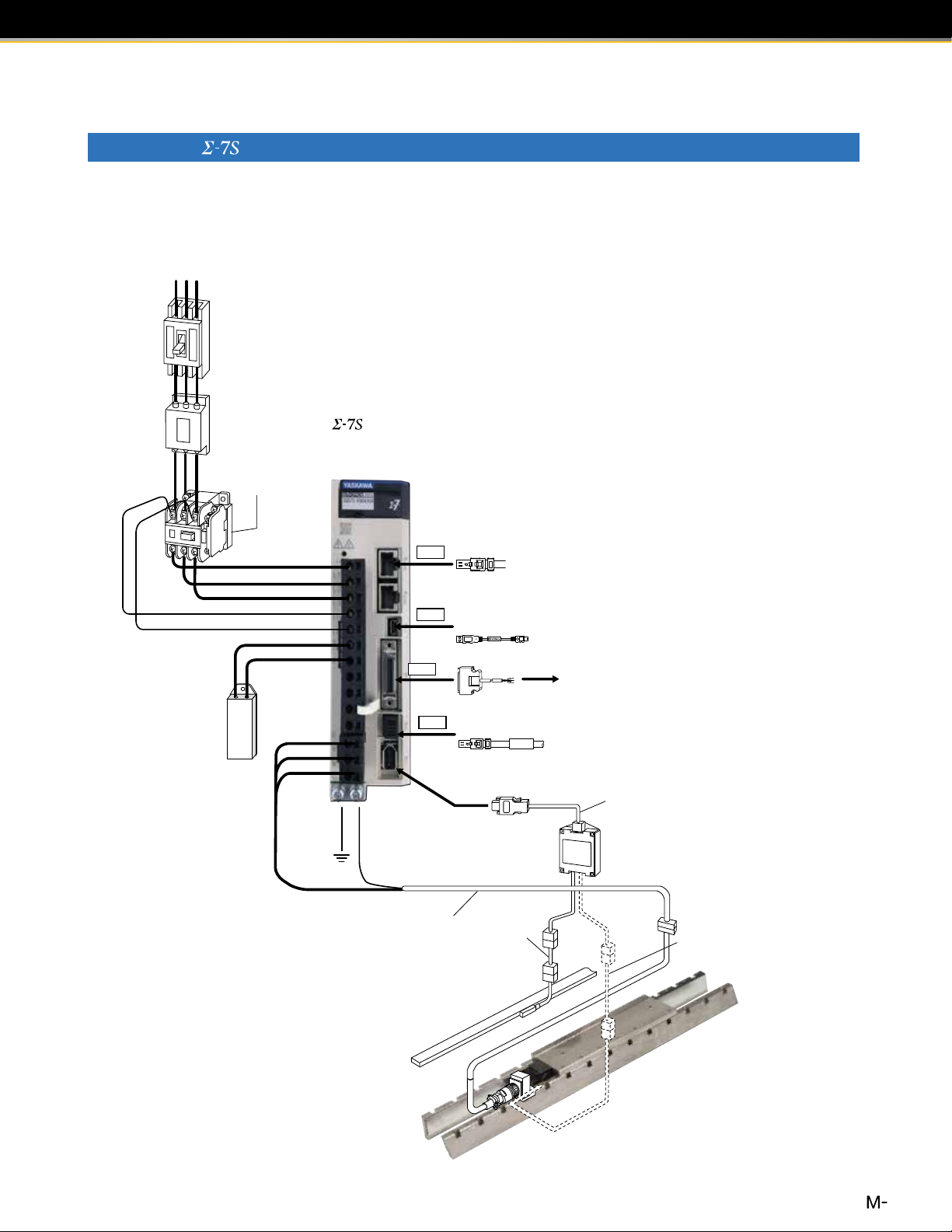
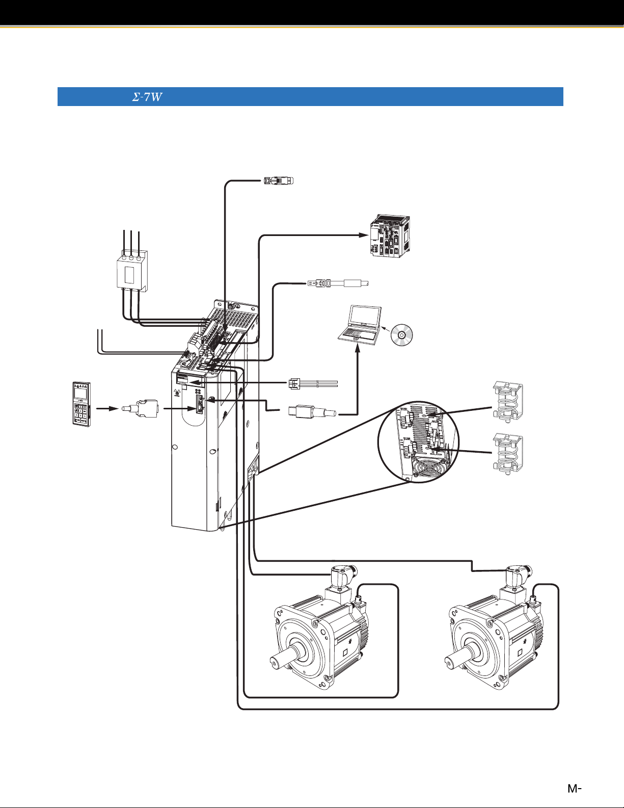
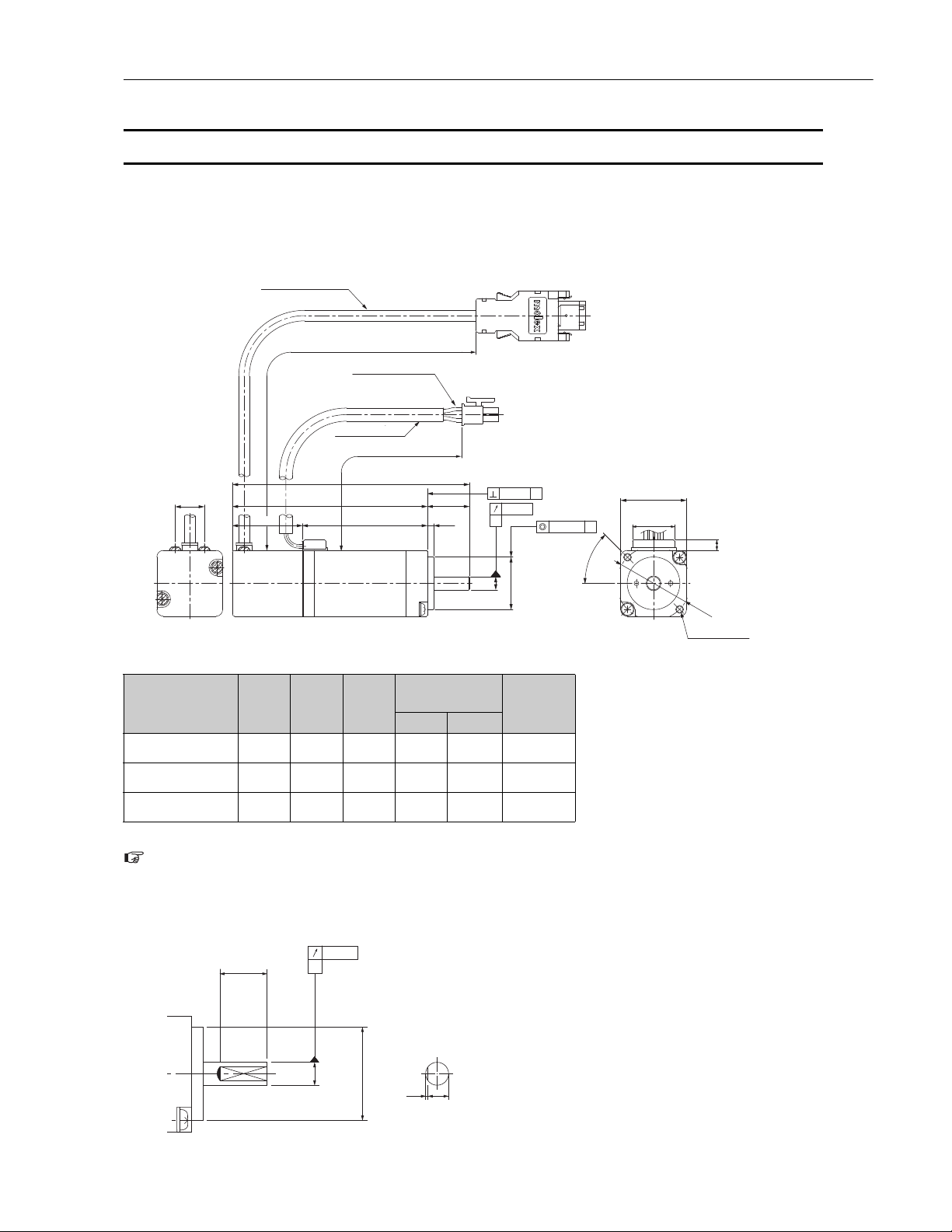
Power supply
Three-phase 200 VAC
R S T
Linear Servomotor
Linear encoder
(Not provided by Yaskawa.)
Sensor Cable
Linear
Encoder
Cable
Linear Servomotor
Main Circuit Cable
Serial Converter Unit
Serial Converter Unit Cable
Noise Filter
Molded-case
circuit breaker
(MCCB)
Protects the power supply
line by shutting the circuit
OFF when overcurrent is
detected.
Used to eliminate
external noise from
the power line.
Magnetic
Contactor
Turns the servo
ON and OFF.
Install a surge
absorber.
Single-axis
MECHATROLINK-III
Communications Reference
SERVOPACK
CN8
External
Regenerative
Resistor
Connect an external
regenerative resistor to
terminals B1 and B2 if the
regenerative capacity is
insufficient.
Note: When not using the safety function, leave
the safety jumper connector connected to
the SERVOPACK.
Safety Function
Devices Cable
I/O Signal Cable
External devices such as
LED indicators
CN6
CN7
Computer Cable
MECHATROLINK Communications Cable
To next
MECHATROLINK-III station
System Conguration Example
Combination of SERVOPACK and Rotary Servomotor/Direct Drive Servomotor (200V Power)
1For MECHATROLINK-III Communications
Three-phase 200 VAC
Power supply
Three-phase 200 VAC
Molded-case
circuit breaker
(MCCB)
Protects the power supply
line by shutting the circuit
OFF when overcurrent is
detected.
Noise Filter
Used to eliminate
external noise from
the power line.
R S T
Magnetic
Contactor
Turns the servo
ON and OFF.
Install a surge
absorber.
Single-axis
MECHATROLINK-III
Communications Reference
SERVOPACK
CN6
MECHATROLINK Communications Cable
To next
MECHATROLINK-III station
External
Regenerative
Resistor
Connect an external
regenerative resistor to
terminals B1 and B2 if the
regenerative capacity is
insufficient.
Magnetic
Contactor
Turns the brake
power supply
ON and OFF.
Install a surge
absorber.
Holding Brake
Power Supply Unit
Used for a
servomotor
with a brake.
(Wiring required for the brake)
Battery Case
(Required when an
absolute encoder is
used.)
Servomotor Main
Circuit Cable
CN7
Computer Cable
I/O Signal Cable
CN1
Safety Function
CN8
Devices Cable
Encoder Cable
External devices such as
LED indicators
Note: When not using the safety function, leave
the safety jumper connector connected to
the SERVOPACK.
CN2
To
Encoder Cable
Servomotor Main
Circuit Cable
Rotary Servomotor
Direct Drive Servomotor
4
Combination of SERVOPACK and Linear Servomotor (200V Power)
1For MECHATROLINK-III Communications
Three-phase 200 VAC
Power supply
Three-phase 200 VAC
R S T
Molded-case
circuit breaker
(MCCB)
Protects the power supply
line by shutting the circuit
OFF when overcurrent is
detected.
Noise Filter
Used to eliminate
external noise from
the power line.
Magnetic
Contactor
Turns the servo
ON and OFF.
Install a surge
absorber.
Single-axis
MECHATROLINK-III
Communications Reference
SERVOPACK
MECHATROLINK Communications Cable
CN6
To next
MECHATROLINK-III station
External
Regenerative
Resistor
Connect an external
regenerative resistor to
terminals B1 and B2 if the
regenerative capacity is
insufficient.
CN7
CN8
Linear Servomotor
Main Circuit Cable
Linear encoder
(Not provided by Yaskawa.)
Computer Cable
I/O Signal Cable
Safety Function
Devices Cable
Linear
Encoder
Cable
External devices such as
LED indicators
Note: When not using the safety function, leave
the safety jumper connector connected to
the SERVOPACK.
Serial Converter Unit Cable
Serial Converter Unit
Sensor Cable
Linear Servomotor
5
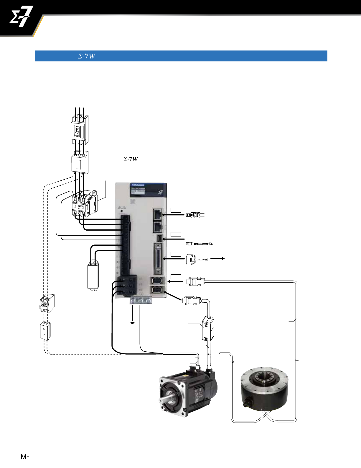
System Conguration Example
Combination of SERVOPACK and Rotary Servomotor/Direct Drive Servomotor (200V Power)
1For MECHATROLINK-III Communications
Three-phase 200 VAC
Power supply
Three-phase 200 VAC
R S T
Molded-case
circuit breaker
(MCCB)
Protects the power supply
line by shutting the circuit
OFF when overcurrent is
detected.
Noise Filter
Used to eliminate
external noise from
the power line.
External
Regenerative
Resistor
Connect an external
regenerative resistor to
terminals B1 and B2 if the
regenerative capacity is
insufficient.
Magnetic
Contactor
Turns the brake
power supply
ON and OFF.
Install a surge
absorber.
Holding Brake
Power Supply Unit
Used for a
servomotor
with a brake.
(Wiring required for the brake)
Magnetic
Contactor
Turns the servo
ON and OFF.
Install a surge
absorber.
Two-axis
MECHATROLINK-III
Communications Reference
SERVOPACK
CN6
CN7
CN1
CN2
Battery Case
(Required when an
absolute encoder is
used.)
Encoder Cable
Servomotor Main
Circuit Cable
MECHATROLINK Communications Cable
Computer Cable
I/O Signal Cable
To next
MECHATROLINK-III station
External devices such as
LED indicators
Servomotor Main
Circuit Cable
Encoder Cable
Rotary Servomotor
Direct Drive Servomotor
6
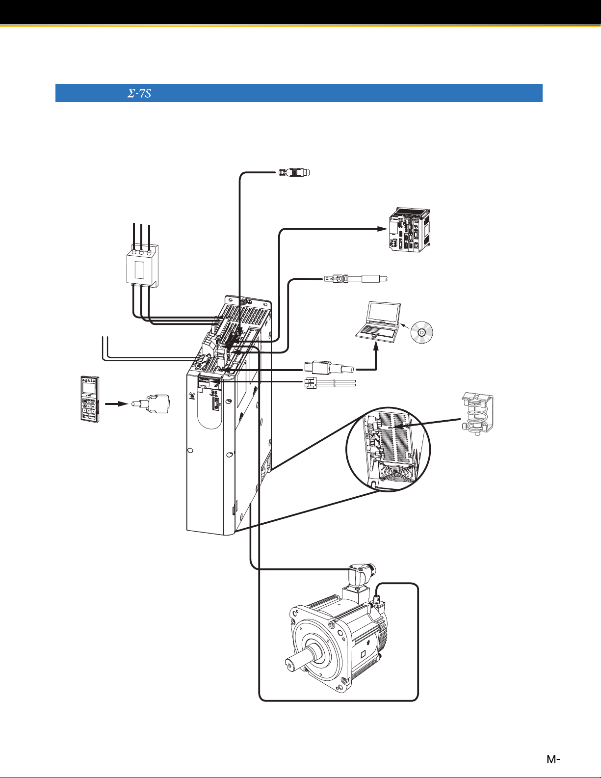
Combination of SERVOPACK and Rotary Servomotor (400V Power)
1For MECHATROLINK-III Communications
Three-phase 400 VAC
Communications Cable
Three-phase, 400 VAC
Noise Filter
Control Power Supply
Cable 24 VDC
L1 L2 L3
SERVOPACK
main circuit wires
Digital
Operator cable
Host controller
CN1 I/O Connector
Safety Function Device Cable
Computer
Support
Software
Computer Cable
Analog Monitor Cable
Motor Connection
Shielding Clamp
Bottom of SERVOPACK
7
System Conguration Example
Power supply
Communications Cable
Digital
Operato
Combination of SERVOPACK and Linear Servomotor (400V Power)
1For MECHATROLINK-III Communications
Three-phase 400 VAC
Three-phase, 400 VAC
L1 L2 L3
Noise Filter
SERVOPACK
main circuit wires
Control Power Supply
Cable 24 VDC
Digital
r
Operator cable
CN1 I/O Connector
Serial Converter Unit
Cable
Host controller
Safety Function Device Cable
Computer
Support
Software
Computer Cable
Analog Monitor Cable
Motor Connection
Shielding Clamp
Bottom of SERVOPACK
Serial Converter Unit
Linear Encoder Cable
Sensor Cable
(between Serial
Linear Encoder
(Not provided by Yaskawa.)
Polarity sensor
Linear Servomotor
Converter Unit and
polarity sensor)
8
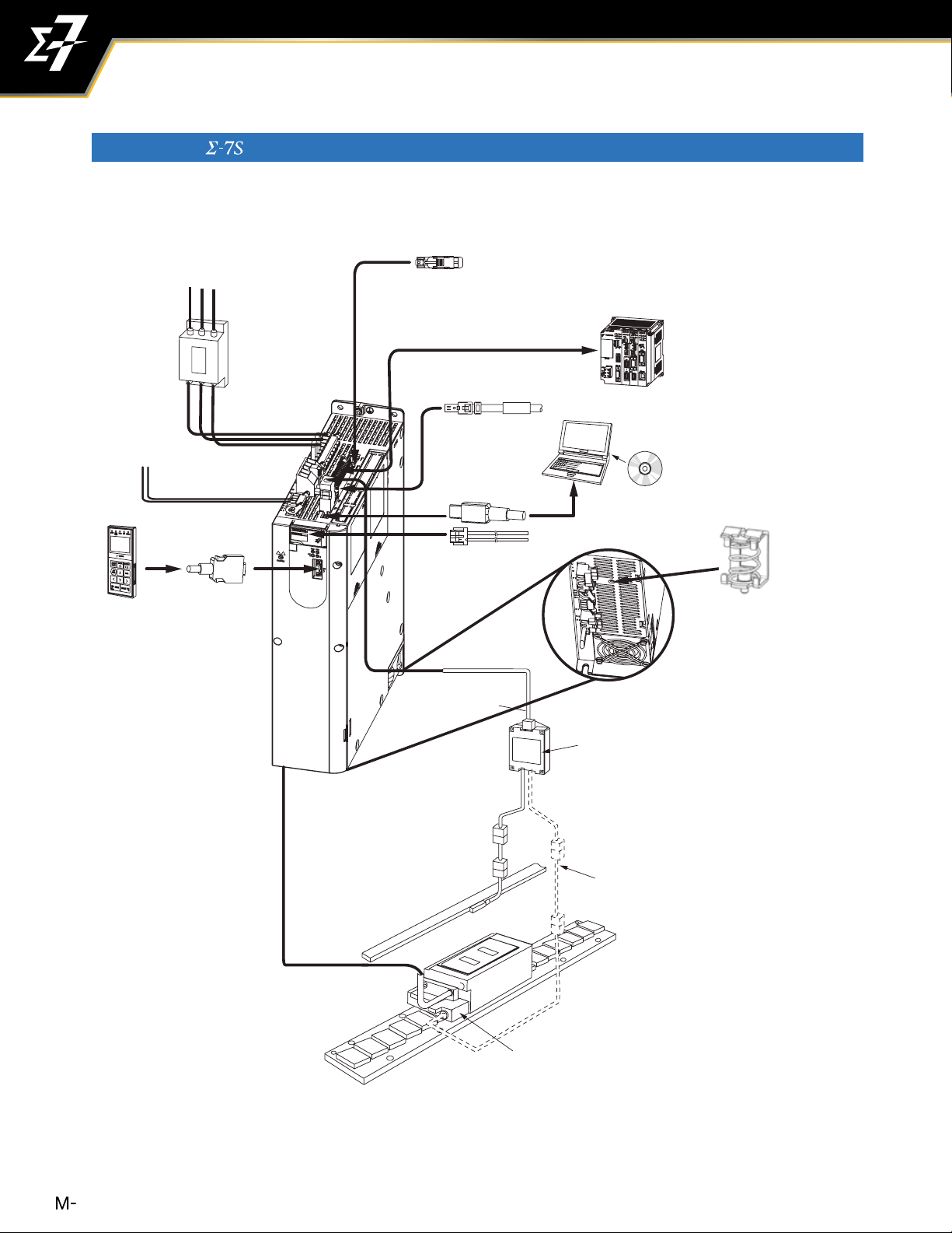
Combination of SERVOPACK and Rotary Servomotors (400V Power)
1For MECHATROLINK-III Communications
Three-phase 400 VAC
Communications Cable
Power supply
Three-phase, 400 VAC
L1 L2 L3
CN1 I/O Connector
Host controller
Noise Filter
Digital
Operator
SERVOPACK
main circuit wires
Control Power Supply
Cable 24 VDC
Digital
Operator cable
Safety Function Device Cable
Computer
Analog Monitor Cable
Computer Cable
Support
Software
Bottom of SERVOPACK
Motor Connection
Shielding Clamps
9
Stock Status Definitions
The product selection tables in this catalog contain stock status codes, which are
subject to change. The codes are defined below:
S
LS
NS
Stock Item
Normally 3 to 5 days leadtime for most order quantities. 3 to 5 weeks maximum
if temporary outages occur. For critical lead time or large quantity shipments,
check with your Yaskawa sales representative.
Limited Stock Item
Typically small quantites are available from stock. Items may become stock
items as demand increases.
Non-Stock Item
Non-stock items typically carry a 12 - 16 week delivery time.
10
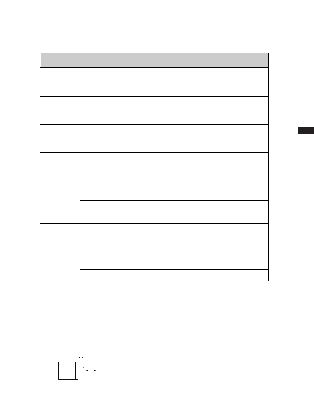
Series Combination
1Combination of Rotary Servomotors and SERVOPACKs
Rotary Servomotor Model
SGMMV
(Low inertia, ultra-
small capacity)
6000 RPM
SGM7J
(Medium inertia, high
speed)
3000 RPM
SGM7A
(Low inertia, high
speed)
3000 RPM
SGM7P
(Medium inertia, at
type)
3000 RPM
SGM7G
(Medium inertia,
large torque)
1500 RPM
Rated
Output
SGMMV-A1A 10 W
SGMMV-A2A 20 W
100V/200V 200V 400V
SGD7S-
R90A, R90F
SGMMV-A3A 30 W 1R6A, 2R1F
SGM7J-A5A 50 W R70A, R70F
SGM7J-01A 100 W R90A, R90F
SGM7J-C2A 150 W
SGM7J-02
SGM7J-04
200 W
400 W 2R8A, 2R8F 2R8A, 5R5A*1, 7R6A
SGM7J-06A 600 W
SGM7J-08
750 W 3R5D 2R6D or 5R4D*
1R6A, 2R1F
5R5A 5R5A, 7R6A
Sigma-7 SERVOPACK Model
SGD7W- SGD7S- SGD7W-
2R9E
*1
*1
, 2R8A
1R6A
−
*1
1R9D
2R6D*
2R6D* or 5R4D*
− −
−
SGM7J-15D 1.5 kW N/A N/A 5R4D 5R4D
SGM7A-A5A 50 W R70A, R70F
SGM7A-01A 100 W R90A, R90R
SGM7A-C2A 150 W
SGM7A-02 200 W
SGM7A-04
400 W 2R8A, 2R8F 2R8A, 5R5A*1, 7R6A
SGM7A-06A 600 W
SGM7A-08
SGM7A-10
750 W 3R5D 2R6D or 5R4D*
1.0 kW
SGM7A-15A 1.5 kW 5R4D 5R4D
1R6A, 2R1F 1R6A, 2R8A
5R5A 5R5A, 7R6A
120A
1R6A
*1
, 2R8A
*1
− −
*1
*1
1R9D
2R6D*
2R6D* or 5R4D*
− −
5R4D 5R4D*
SGM7A-20A 2.0 kW 180A 8R4D
SGM7A-25A 2.5 kW
SGM7A-30A 3.0 kW 120D
SGM7A-40A 4.0 kW
SGM7A-50A 5.0 kW 170D
SGM7A-70A 7.0 kW 550A
SGM7P-01A 100 W R90A, R90F 1R6A
SGM7P-02A 200 W
SGM7P-04A 400 W
200A
330A
*1
2R8A, 2R8F 2R8A, 5R5A
−
, 2R8A
*1
, 7R6A
*1
*1
120D
170D
−
− −
−
SGM7P-08A 750 W 5R5A 5R5A, 7R6A
SGM7P-15A 1.5 kW 120A
SGM7G-03A 300 W
SGM7G-05A 450 W 1R9D 2R6D or 5R4D*
3R8A 5R5A
−
*1
, 7R6A
*1
− −
SGM7G-09A 850 W 7R6A 7R6A 3R5D 5R4D*
SGM7G-13A 1.3 kW 120A
SGM7G-20A 1.8 kW 180A 8R4D
SGM7G-30A 2.9 kW
SGM7G-44A 4.4 kW 170D
SGM7G-55A 5.5 kW 470A 210D
*2
330A
−
5R4D 5R4D
120D
−
SGM7G-75A 7.5 kW 550A 260D
SGM7G-1AA 11 kW 590A 280D
SGM7G-1EA 15 kW 780A 370D
*1. If you use this combination, performance may not be as good, e.g., the control gain may not increase, in comparison with using a SERVOPACK.
*2. The rated output is 2.4 kW if you combine the SGM7G-30A with the SGD7S-200A.
11
Series Combination
1Combination of Direct Drive Servomotors and SERVOPACKs
Direct Drive Servomotor Model
SGM7D
(With core, outer rotor)
SGM7F
(With core, inner rotor)
Small capacity, coreless
(SGMCS)
Medium capacity, with core
(SGMCS)
Rated Torque
Nm
SGM7D-30F 30.0 50.0
SGM7D-58F 58.0 100
SGM7D-90F 90.0 150
SGM7D-1AF 110 200
SGM7D-01G 1.30 4.00
SGM7D-05G 5.00 6.00
SGM7D-08G 8.00 15.0
SGM7D-18G 18.0 30.0
SGM7D-24G 24.0 45.0
SGM7D-34G 34.0 60.0
SGM7D-45G 45.0 75.0
SGM7D-03H 3.00 4.00 2R8A, 2R8F
SGM7D-28I 28.0 50.0
SGM7D-70I 70.0 100
SGM7D-1ZI 100 150
SGM7D-1CI 130 200
SGM7D-2BI 220 300
SGM7D-2DI 240 400
SGM7D-06J 6.00 8.00
SGM7D-09J 9.00 15.0
SGM7D-18J 18.0 30.0
SGM7D-20J 20.0 45.0
SGM7D-38J 38.0 60.0
SGM7D-02K 2.06 5.00
SGM7D-06K 6.00 10.0
SGM7D-08K 8.00 15.0
SGM7D-06L 6.00 10.0
SGM7D-12L 12.0 20.0
SGM7D-30L 30.0 40.0 120A
SGM7F-02A 2 6
SGM7F-05A 5 15
SGM7F-07A 7 21
SGM7F-10B 10 30
SGM7F-14B 14 42 5R5A
SGM7F-08C 8 24 2R8A, 2R8F 2R8A
SGM7F-17C 17 51 5R5A
SGM7F-25C 25 75 7R6A
SGM7F-16D 16 48 5R5A
SGM7F-35D 35 105 7R6A, 120A 7R6A
SGMCS-02B 2 6
SGMCS-05B 5 15
SGMCS-07B 7 21
SGMCS-04C 4 12
SGMCS-10C 10 30
SGMCS-14C 14 42
SGMCS-08D 8 24
SGMCS-17D 17 51
SGMCS-25D 25 75
SGMCS-16E 16 48
SGMCS-35E 35 105
SGMCS-45M 45 135 7R6A
SGMCS-80M 80 240
SGMCS-80N 80 240
SGMCS-1AM 110 330 180A
SGMCS-1EN 150 450
SGMCS-2ZN 200 600
Instantaneous
Max. Torque
Nm
SGD7S-
SERVOPACK Model
SGD7W-
120A
2R8A, 2R8F
120A
120A
2R8A, 2R8F
2R8A, 2R1F
2R8A
2R8A, 2R8FSGM7F-04B 4 12
2R8A
5R5A
120A
200A
−
−
12
Series Combination
1Combination of Linear Servomotors and SERVOPACKs
Linear Servomotor Model
SGLGW-30A050C 12.5 40 R70A, R70F
SGLGW-30A080C 25 80
SGLGW-40A140C 47 140
SGLGW-40A253C 93 280 1R6A, 2R1F
SGLG
(Coreless model, with
standard magnetic way)
SGLG
(Coreless model, with high-
force magnetic way)
SGLFW2*
SGLF
(Model with F-type iron core)
SGLFW*
SGLT
(Model with T-type iron core)
ST2F
(Sigma Trac II
Linear Stages)
*: The SGLFW model is an earlier product. Select the SGLFW2 model when newly installing a linear servomotor to a machine.
SGLGW-40A365C 140 420 2R8A, 2R8F 2R8A
SGLGW-60A140C 70 220 1R6A, 2R1F 1R6A
SGLGW-60A253C 140 440 2R8A, 2R8F 2R8A
SGLGW-60A365C 210 660 5R5A
SGLGW-90A200C 325 1300 120A
SGLGW-90A535C 750 3000 200A
SGLGW-40A140C 57 230 1R6A, 2R1F 1R6A
SGLGW-40A253C 114 460 2R8A, 2R8F 2R8A
SGLGW-40A365C 171 690 3R8A 5R5A
SGLGW-60A140C 85 360 1R6A, 2R1F 1R6A
SGLGW-60A253C 170 720 3R8A 5R5A
SGLGW-60A365C 255 1080 7R6A
SGLFW2-30A070A 45 135
SGLFW2-30A120A 90 270
SGLFW2-30A230A
SGLFW2-45A200A 280 840 5R5A
SGLFW2-45A380A 560
SGLFW2-90A200A 560 1680
SGLFW2-90A380A 1120 3360 200A
SGLFW2-90A560A 1680 5040 330A
SGLFW2-1DA380A 1680 5040 200A
SGLFW2-1DA560A 2520 7560 330A
SGLFW-20A090A 25 86
SGLFW-35A120A 80 220
SGLFW-35A230A 160 440 3R8A 5R5A
SGLFW-50A200B 280 600 5R5A
SGLFW-50A380B
SGLFW-1ZA380B 1120 2400 200A
SGLTW-20A170A 130 380 3R8A 5R5A
SGLTW-20A320A 250 760 7R6A
SGLTW-20A460A 380 1140 120A −
SGLTW-35A170A 220 660
SGLTW-35A170H 300 600
SGLTW-35A320A 440 1320
SGLTW-35A320H 600 1200
SGLTW-35A460A 670 2000
SGLTW-40A400B 670 2600
SGLTW-40A600B 1000 4000 330A
SGLTW-50A170H 450 900 5R5A
SGLTW-50A320H 900 1800 120A
SGLTW-80A600B 2000 7500 550A
SGT2F-A1A 45 135
SGT2F-A2A 90 270
SGT2F-A3A 180 540 3R8A, 2R8A, 2R8F 2R8A, 2R8F
SGT2F-A1D 45 135
SGT2F-A3D 180 540
Rated ForceNMax. Force
N
180 540 3R8A −
170 500 2R8A, 2R8F 2R8A
1680 180A
1500
560 1200 120A
SERVOPACK Model
SGD7S-
R90A, R90F
1R6A, 2R1F 1R6A
120A
1R6A, 2R1F 1R6ASGLFW-20A120A 40 125
120A
180A
1R6A, 2R1F 1R6A
1R9D 2R6DSGT2F-A2D 90 270
SGD7WSGD7C-
5R5A
1R6A
−SGLGW-90A370C 550 2200 180A
−
−SGLFW-1ZA200B
−
−SGLTW-80A400B 1300 5000 330A
13
Recommended Encoders
1Incremental Linear Encoders
Output Signal Manufacturer
Heidenhain
1 Vp-p Analog
Voltage
*1
Corporation
Renishaw plc*4Exposed
Encoder
Type
Exposed
Scale
LIDA48
LIF48
RGS20 RGH22B
SL7 0
SQ10 PQ10
Linear
Encoder for
Yaskawa’s Serial
Interface
*2
Magnescale
Co., Ltd.
Exposed
BL57-
( -LINK)
BF1-
BF1- RY F
SR75-
Sealed
SR75- MF − 80 78.1 3.33 −
SR85- LF − 80 9.8 3.33 −
SR85- MF − 80 78.1 3.33 −
*1: You must also use a Yaskawa Serial Converter Unit. The output signal will be
multiplied by 8 bits (256 divisions) or 12 bits (4,096 divisions) in the Serial Converter
Unit.
*2: The multiplier (number of divisions) depends on the Linear Encoder. Also, you must
write the motor constant file to the Linear Encoder in advance.
*3: The maximum speeds given in the above table are the maximum applicable speeds
of the encoders when combined with a Yaskawa SERVOPACK. The actual speed
will be restricted by either the maximum speed of the Linear Servomotor or the
maximum speed of the Linear Encoder (given above).
Model
Sensor
Head
PL101 MJ620-T13
*8
RED
RY F
LF − 80 9.8 3.33 −
Linear
Interpolator (Serial
Encoder
Converter Unit)
JZDP-H003/-H006
JZDP-J003/- J006
JZDP-H003/-H006
JZDP-J003/- J006
JZDP-H005/-H008
JZDP-J005/- J008
PL101-RY
*5
*5
*5
*5
*5
*5
*6
*7 *8
MQ10-FLA
MQ10-GLA −
ResolutionnmMaximum
Pitch
μ
m
78.1 5
20
4
20
4.9 2
15.6 1
1.0 0.4
78.1 5
4.9 2
800 97.7 10
400 48.83 3
Speed
m/s
Support for
*3
Polarity
Sensor
Input
−
−
Application
to Linear
Motors
*8 *8
BD96-Y1051LC 0.4 0.78 0.8 −
BD96-Y1025LC 0.4 1.56 1.0
BD96-Y2051LC 0.4 0.78 0.8
BD96-Y2025LC 0.4 1.56 1.0
BD96-YJ051LC 0.4 0.78 0.8
BD96-YJ025LC 0.4 1.56 1.0
*8
*8
*4: If you use the origin signals with a Linear Encoder from Renishaw plc, the origin may
sometimes be falsely detected. If that occurs, use the BID/DIR signal to output the
origin signal only in one direction.
*5: Use this model number to purchase the Serial Converter Unit.
*6: Use this model number to purchase the Sensor Head with Interpolator.
*7: Use this model number to purchase the Interpolator.
*8: Contact your Yaskawa representative.
Note: 1. Confirm detailed specifications, such as the tolerances, dimensions, and
2.
0.25 0.49 1.77
0.25 0.98 1.8
operating environment, with the manufacturer of the Encoder before you use it.
-LINK is a registered trademark of YASKAWA ELECTRIC CORPORATION.
: Possible
Application to
Fully-Closed
Loop Control
*8
*8
−
−
−
−
−
1Absolute Rotary Encoder
The following Absolute Rotary Encoders are for fully-closed control. Can not use it to control the motor.
Output Signal Manufacturer
Magnescale
Co., Ltd.
Rotary Encoder
Type
Sealed
Exposed ECA4412
Encoder for Yaskawa’s
Serial Interface
-LINK)
(
Heidenhain
Corporation
Sealed
RA23Y-
Renishaw plc Exposed
RA26Y-
RA30Y-
*1: The maximum speeds given in the above table are the maximum applicable speeds
of the encoders when combined with a Yaskawa SERVOPACK. The actual speed
will be restricted by either the maximum speed of the Linear Servomotor or the
maximum speed of the Linear Encoder (given above).
*2: This is a single-turn absolute encoder.
Model
Scale Sensor Head
RU77-4096ADF
RU77-4096AFFT01
RCN2
RCN5
RCN8
ROC2310
ROC7310
*2
*2
*2
*2
10
*2
10
*2
10
*2
*2
Note: 1. Confirm detailed specifications, such as the tolerances, dimensions, and
operating environment, with the manufacturer of the Encoder before you use it.
2.
-LINK is a registered trademark of YASKAWA ELECTRIC CORPORATION.
Relay Device between Fully-Closed
*2
*2
*2
14
Module and Rotary Encoder
− 20 2000
− 22 2000
EIB3391Y
− 23 14600
− 26 3250
− 30 200
Resolution
Bits
27 1600
28 800
29 400
26 3000
28 800
29 400
26 3000
28 800
Maximum Speed*1
RPM
1Absolute Linear Encoder
: Possible
Model
Sensor
Head
S F
T F
A F
F F
S F
T F
A F
F F
LF − 80 9.8 3.33 −
Output Signal Manufacturer
Magnescale
Co., Ltd.
Linear
Encoder
Type
Exposed
Sealed
Scale
SQ47
-
SQ47
-
SQ47
-
SQ47
-
SQ57
-
SQ57
-
SQ57
-
SQ57
-
SR77-
SR77- MF − 80 78.1 3.33 −
SR87- LF − 80 9.8 3.33 −
SR87- MF − 80 78.1 3.33 −
ST781A − 256 500 5 −
Encoder for
Yaskawa’s Serial
Interface
*1
( -LINK)
Mitutoyo
Corporation
Exposed
ST782A − 256 500 5 −
ST783A − 51.2 100 5 −
ST784A − 51.2 100 5 −
ST788A − 51.2 100 5 −
ST789A
*4
ST1381 − 5.12 10 8 −
ST1382 − 0.512 1 3.6
LIC4100 Series
Heidenhain
Corporation
Exposed
Sealed
LIC2100 Series
LC115 40.96 10 3 −
LC415 40.96 10 3 −
EL36Y-050F
EL36Y
- 1
00F
Renishaw plc
Exposed
EL36Y
- 5
RL36Y-05
00F
0 − 12.8 50 100 −
RL36Y-001
*1: The multiplier (number of divisions) depends on the Linear Encoder. Also, you must
write the motor constant file to the Linear Encoder in advance.
*2: These are reference values for setting SERVOPACK parameters. Contact the
manufacturer for actual linear encoder scale pitches.
*3: The maximum speeds given in the above table are the maximum applicable speeds
of the encoders when combined with a Yaskawa SERVOPACK. The actual speed
will be restricted by either the maximum speed of the Linear Servomotor or the
maximum speed of the Linear Encoder (given above).
*4: Contact Mitutoyo Corporation for details on the Linear Encoders.
Interpolator (Serial
Converter Unit)
Linear
Encoder
*2
Pitch
μ
m
Resolution
nm
Maximum
Speed
m/s
Support for
*3
Polarity
Sensor
Input
− 20.48 5 3.33 −
− 40.96 10 3.33 −
− 20.48 5 3.33 −
− 40.96 10 3.33 −
− 25.6 50 5 −
*6
−
20.48 5 10 −
204.8 50 10 −
*5
EIB3391Y
409.6 100 10 −
− 12.8 50 100 −
− 25.6 100 100 −
− 128 500 100 −
− 0.256 1 3.6 −
*5: Use this model number to purchase the Interpolator.
*6: The speed is restricted for some SERVOPACKs.
Note: 1. Confirm detailed specifications, such as the tolerances, dimensions, and
operating environment, with the manufacturer of the Encoder before you use it.
2.
-LINK is a registered trademark of YASKAWA ELECTRIC CORPORATION.
Application
to Linear
Motors
Application to
Fully-Closed
Loop Control
15
Related Documents
The documents that are related to the MP3300 Machine Controllers and series AC Servo Drives are
shown in the following table. Refer to these documents as required.
Brochure/Catalog Name
(Document No.)
Yaskawa Motion Product Brochure:
Condent, Consistent, Capable
(BL.MTN.01)
Series AC Servo Drives and Motors
Technical Supplement
(YAI-KAEPS80000123)
Manual Name
(Manual No.)
−
MP3300iec Machine Controller
Hardware Manual
(YAI-SIA-IEC-7)
SERVOPACK with
MECHATROLINK-3 Communications References
Product Manual
(SIEPS80000128)
SERVOPACK with Analog
Voltage/Pulse Train References
Product Manual
(SIEPS80000126)
SERVOPACK with EtherCAT (CoE)
Communication References
Product Manual
(SIEPS80000155)
SERVOPACK with
MECHATROLINK-3 Communications References
Product Manual
(SIEPS80000129)
-Series/ -Series for LargeCapacity Models/ -Series User’s
Manual Safety Module
(SIEPC72082906)
Rotary Servomotor Product Manual
(SIEPS80000136)
Linear Servomotor Product Manual
(SIEPS80000137)
Direct Drive Servomotor Product Manual
(SIEPS80000138)
Description of Document
This brochure presents an introduction to
Yaskawa America Motion Products and
services, with an emphasis on AC Servo,
Machine Controller, and IO products.
Provides detailed information on selection
and installation MP3300iec machine
controller components/accessories.
Provides detailed information on
selecting
and information on installing,
connecting, setting, performing
trial operation for, tuning, and monitoring the
Servo Drives.
Provides details information required for the
design and maintenance of a Safety Module.
Provide detailed information on
selecting, installing, and connecting
the
-Series SERVOPACKs
-Series Servomotors.
16
Peripheral Device Selection Manual
(SIEPS80000132)
MECHATROLINK-3 Communications
Standard Servo Prole Command Manual
(SIEPS80000131)
Digital Operator Operating Manual
(SIEPS80000133)
Engineering Tool
SigmaWin+ Online Manual
Component
(SIEPS80000148)
Describes the peripheral devices
for a
Provides detailed information on the
MECHATROLINK-3 communications
standard servo prole commands that are
used for a - Series Servo System.
Describes the operating procedures for a Digital
Operator for a -Series Servo System.
Provides detailed operating procedures
for the SigmaWin+ Engineering Tool
for a -Series Servo System.
-Series Servo System.
Brochure/Catalog Name
(Document No.)
Series AC Servo Drives and Motors
Technical Supplement
(YAI-KAEPS80000123)
Manual Name
(Manual No.)
SERVOPACK with 400V-Input
Power and EtherCAT (CoE) Communications References Product Manual
(SIEPS80000180)
SERVOPACK with 400V-Input
Power and MECHATROLINK III
Communications References Product
Manual (SIEPS80000214)
SERVOPACK with 400V-Input
Power and EtherCAT (CoE)
Communications References Product
Manual (SIEPS80000219)
SERVOPACK with
400V-Input Power and MECHATROLINK
III Communications References Product
Manual(SIEPS80000220)
-Series User Manual Safety Module
(SIEPC 72082906E)
Supplement for using with Sigma-7
SERVOPACKs (400 V-Input power
models) (900-200-100)
Rotary Servomotor with 400 V-Input
Power Product Manual
(SIEPS80000186)
Linear Servomotor with 400 V-Input
Power Product Manual
(SIEPS8000181)
Description of Document
Provides detailed information on
selecting
and information on installing, connecting,
setting, performing trial operation for, tuning,
and monitoring the Servo Drives.
Provides details information required for the
design and maintenance of a Safety Module.
Provide detailed information on
selecting, installing, and connecting
the
-Series SERVOPACKs
-Series Servomotors.
17

18
CONTENTS
Rotary Servo Motors
SGMMV 4
SGM7J 18
SGM7A 54
SGM7P 116
SGM7G 134
Direct Drive Servo Motors
SGM7F (With Core, Inner Rotor) 190
SGM7D (With Core, Outer Rotor) 206
SGMCS (Small Capacity, Coreless or Medium Capacity, with Core) 234
Linear Servo Motors
SGLFW2 (Models with F-type Iron Cores, 200V) 260
SGLFW2 (Models with F-type Iron Cores, 400V) 288
SGLG (Coreless Models) 308
SGLT (Models with T-type Iron Cores) 338
Recommended Linear Encoders and Cables 368
SGLFW (Earlier Models with F-type Iron Cores) 392
Linear Stages
ST2F Sigma Trac II Linear Stages 418
SERVOPACKs
Single-axis Analog Voltage/Pulse Train Reference SERVOPACKs
Single-axis MECHATROLINK-III Communications Reference SERVOPACKs
Single-axis EtherCAT Communications Reference SERVOPACKs
Two-axis MECHATROLINK-III Communications Reference SERVOPACKs
Two-axis EtherCAT Communications Reference SERVOPACKs
SERVOPACK External Dimensions 484
Option Modules
Feedback Option Module 500
Safety Option Module 506
Sigma-7Siec Option 510
MP2600iec Option 512
SigmaLogic7 Compact Option 520
FT19 Option - Less Deviation Control 522
FY79 Option - Built-in Indexer 524
424
434
448
464
478
FT81 Option - Support for Harmonic Drive SHA Series Actuators 526
FT82/83 Option - Support for SGM7D Direct Drive Motor 528
1

Cables and Peripheral Devices
Cables for SERVOPACKs 530
Peripheral Devices 540
Appendices
Capacity Selection for Servo Motors 572
Capacity Selection for Regenerative Resistors 582
International Standards 598
Warranty 600
2

Rotary Servo Motors
SGMMV .................................................................. 4
SGM7J .................................................................. 18
SGM7A ................................................................. 54
SGM7P ................................................................116
SGM7G ................................................................134
Rotary Servo Motors
SGMMV
Model Designations
-
SGMMV
-V mini Series
Servo Motors:
SGMMV
A1
1st+2nd
digits
A 2 A
3rd
digit
4th
digit
5th
digit
21
6th
digit
7th
digit
1st+2nd digits
Code Specification
A1 10 W
A2 20 W
A3 30 W
Rated Output
3rd digit
Code Specification
4th digit
Code
5th digit
Power Supply Voltage
A 200 VAC
Serial Encoder
17-bit absolute
2
Design Revision Order
A
Specification
6th digit Shaft End
Code Specification
Straight
2
Straight with flat seats
A
7th digit Options
Code
1
C
Non Stock Items
Specification
Without options
With holding brake (24 VDC)
4
Rotary Servo Motors
Rotary Servo Motors
Vertical
Shock Applied to the Servo Motor
SGMMV
Specifications and Ratings
Specifications
Voltage 200 V
Model SGMMV- A1A A2A A3A
Time Rating Continuous
Thermal Class B
Insulation Resistance 500 VDC, 10 M min.
Withstand Voltage 1,500 VAC for 1 minute
Excitation Permanent magnet
Mounting Flange-mounted
Drive Method Direct drive
Rotation Direction
Vibration Class
*1
Surrounding Air Temperature
Surrounding Air Humidity 20% to 80% relative humidity (with no condensation)
Environmental
Installation Site
Conditions
Storage Environment
Shock
Resistance
Vibration
Resistance
Applicable
SERVOPACKs
Impact Acceleration Rate at
Flange
*2
Number of Impacts 2 times
Vibration Acceleration Rate
*3
at Flange
SGD7S- R90A, R90F 1R6A, 2R1F
SGD7W-
*1. A vibration class of V15 indicates a vibration amplitude of 15 m maximum on the Servo Motor without a load at the
rated motor speed.
*2. The shock resistance for shock in the vertical direction when the Servo Motor is mounted with the shaft in a horizontal
position is given in the above table.
Counterclockwise (CCW) for forward reference when viewed from the
load side
V15
0°C to 40°C
• Must be indoors and free of corrosive and explosive gases.
• Must be well-ventilated and free of dust and moisture.
• Must facilitate inspection and cleaning.
• Must have an altitude of 1,000 m or less.
• Must be free of strong magnetic fields.
Store the Servo Motor in the following environment if you store it with
the power cable disconnected.
Storage Temperature: -20°C to 60°C (with no freezing)
Storage Humidity: 20% to 80% relative humidity (with no condensation)
2
490 m/s
2
49 m/s
1R6A
*4
, 2R8A
*4
1R6A, 2R8A
*4
5

Rotary Servo Motors
Vertical
Horizontal direction
Vibration Applied to the Servo Motor
Front to back
Side to side
SGMMV
*3. The vertical, side-to-side, and front-to-back vibration resistance for vibration in three directions when the Servo Motor
is mounted with the shaft in a horizontal position is given in the above table. The strength of the vibration that the
Servo Motor can withstand depends on the application. Always check the vibration acceleration rate that is applied to
the Servo Motor with the actual equipment.
*4. If you use a S-7W SERVOPACK, the control gain may not increase as much as with a S-7S SERVOPACK and other
performances may be lower than those achieved with a S-7S SERVOPACK.
6
Rotary Servo Motors
Servo Motor Ratings
+10%
0
LF
Radial load
Thrust load
Vol tage 200 V
Model SGMMV
Rated Output
Rated Torque
Instantaneous Maximum Torque
Rated Current
Instantaneous Maximum Current
Rated Motor Speed
Maximum Motor Speed
*1
*1, *2
*1
*1
*1
-
W102030
N•m 0.0318 0.0637 0.0955
*1
*1
N•m 0.0955 0.191 0.286
Arms 0.70 0.66 0.98
Arms 2.0 1.9 2.9
-1
min
-1
min
Torque Constant N•m/Arms 0.0516 0.107
-7
Motor Moment of Inertia
Rated Power Rate
*1
Rated Angular Acceleration Rate
10
kW/s 3.72 8.71 13.7
*1
rad/s
kg•m
2
2
Heat Sink Size (Aluminum) mm 150 x 50 x 3 250 x 250 x 6
Protective Structure
*3
Rated Voltage V
Capacity W 2.0 2.6
Holding Torque N•m 0.0318 0.0637 0.0955
Holding Brake
Specifications
Coil Resistance (at 20°C) 320 221.5
*4
Rated Current A (at 20°C) 0.075 0.108
Time Required to
Release Brake
Time Required to
Brake
ms 40
ms 100
Allowable Load Moment of Inertia
(Motor Moment of Inertia Ratio)
With External Regenerative
Resistor and Dynamic Brake
Resistor
LF mm 16
Allowable Shaft
*5
Loads
Allowable Radial
Load
Allowable Thrust
Load
N34 44
N 14.5
A1A A2A A3A
3000
6000
2.72 (4.07) 4.66 (6.02) 6.68 (8.04)
117000 137000 143000
Totally enclosed, self-cooled, IP55
(except for shaft opening)
24 VDC
30 times
30 times
Rotary Servo Motors
SGMMV
*1. These values are for operation in combination with a SERVOPACK when the temperature of the armature winding is
20°C. These are typical values.
*2. The rated torques are the continuous allowable torque values with an aluminum or steel heat sink of the dimensions
given in the table.
*3. This does not apply to the shaft opening. Protective structure specifications apply only when the special cable is used.
*4. Observe the following precautions if you use a Servo Motor with a Holding Brake.
• The holding brake cannot be used to stop the Servo Motor.
• The time required to release the brake and the time required to brake depend on which discharge circuit is used.
Confirm that the operation delay time is appropriate for the actual equipment.
• The 24-VDC power supply is not provided by Yaskawa.
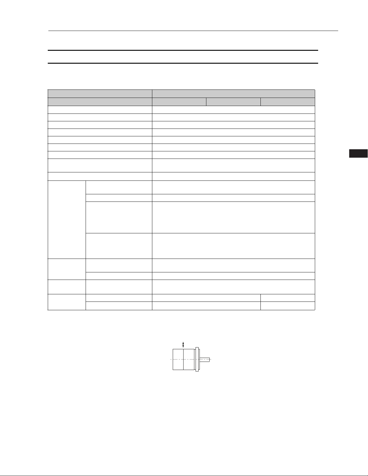
*5. The allowable shaft loads are illustrated in the following figure. Design the mechanical system so that the thrust and
radial loads applied to the Servo Motor shaft end during operation do not exceed the values given in the table.
Note: The values in parentheses are for Servo Motors with Holding Brakes.
7
Rotary Servo Motors
SGMMV-A3A
A
B
4000
3000
2000
1000
0
5000
6000
7000
0 0.1 0.2 0.3 0.4
SGMMV-A1A
A
B
4000
3000
2000
1000
0
5000
6000
7000
0 0.04 0.08 0.12 0.16
SGMMV-A2A
A
B
4000
3000
2000
1000
0
5000
6000
7000
0 0.08 0.16 0.24 0.32
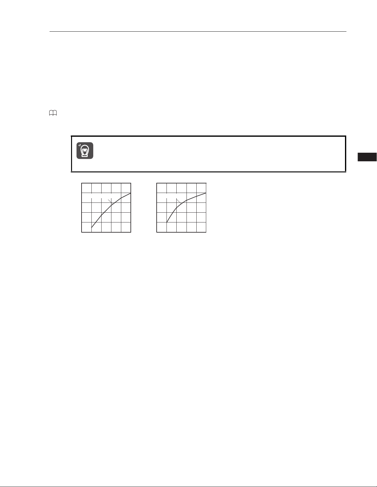
Continuous duty zone
Intermittent duty zone*
A
:
B
:
Motor speed (min
-1
)
Torque (N·m)
Motor speed (min
-1
)
Torque (N·m)
Motor speed (min
-1
)
Torque (N·m)
SGMMV
Torque-Motor Speed Characteristics
* The characteristics are the same for three-phase 200 V, single-phase 200 V, and single-phase 100 V input.
Note: 1. These values are for operation in combination with a SERVOPACK when the temperature of the armature winding
is 20°C. These are typical values.
2. The characteristics in the intermittent duty zone depend on the power supply voltage.
3. If the effective torque is within the allowable range for the rated torque, the Servo Motor can be used within the
intermittent duty zone.
4. If you use a Servo Motor Main Circuit Cable that exceeds 20 m, the intermittent duty zone in the torque-motor
speed characteristics will become smaller because the voltage drop increases.
8
Rotary Servo Motors
Rotary Servo Motors
1000
100
10
1
100 200 300
SGMMV-A1 ,-A2 ,-A3
Detection time (s)
Torque reference (percent of rated torque)
(%)
SGMMV
Servo Motor Overload Protection Characteristics
The overload detection level is set for hot start conditions with a Servo Motor surrounding air temperature
of 40
°C.
Note: The above overload protection characteristics do not mean that you can perform continuous duty operation with an
output of 100% or higher. Use the Servo Motor so that the effective torque remains within the continuous duty zone
given in Torque-Motor Speed Characteristics (page 8).
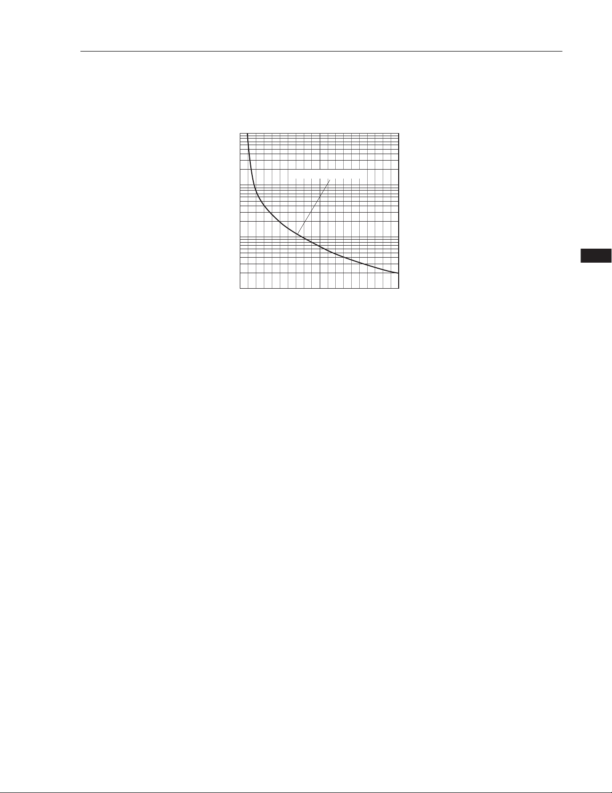
Load Moment of Inertia
The load moment of inertia indicates the inertia of the load. The larger the load moment of inertia, the
worse the response. If the moment of inertia is too large, operation will become unstable.
The allowable size of the load moment of inertia (J
Motor Ratings (page 7). This value is provided strictly as a guideline and results depend on Servo Motor
driving conditions.
An Overvoltage Alarm (A.400) is likely to occur during deceleration if the load moment of inertia exceeds
the allowable load moment of inertia. SERVOPACKs with a built-in regenerative resistor may generate a
Regenerative Overload Alarm (A.320). Perform one of the following steps if this occurs.
• Reduce the torque limit.
• Reduce the deceleration rate.
• Reduce the maximum motor speed.
• Install an External Regenerative Resistor if the alarm cannot be cleared using the above steps.
Regenerative resistors are not built into SERVOPACKs for 400-W Servo Motors or smaller Servo Motors.
Even for SERVOPACKs with built-in regenerative resistors, an External Regenerative Resistor is
required if the energy that results from the regenerative driving conditions exceeds the allowable loss
capacity (W) of the built-in regenerative resistor.
) for the Servo Motor is restricted. Refer to Servo
L
9
Rotary Servo Motors
0
1000 2000 3000 4000 5000 6000 7000
0
35
30
25
20
15
10
5
Allowable load moment of inertia
scaling factor (times)
Motor speed (min-1)
SGMMV-A1A, -A2A, -A3A
SGMMV
Allowable Load Moment of Inertia Scaling Factor for SERVOPACKs
without Built-in Regenerative Resistors
The following graphs show the allowable load moment of inertia scaling factor of the motor speed for
SERVOPACKs* without built-in regenerative resistors when an External Regenerative Resistor is not
connected.
If the Servo Motor exceeds the allowable load moment of inertia, an overvoltage alarm may occur in the
SERVOPACK.
These graphs provide reference data for deceleration at the rated torque or higher.
* Applicable SERVOPACK models: SGD7S-R90A, -1R6A, -R90F, and -2R1F
10
Rotary Servo Motors
Rotary Servo Motors
Important
90 150120
60
300 150 250200
100
500
100
80
60
40
20
100
80
60
40
20
SGMMV-A1, -A2
SGMMV-A3
Derating rate (%)
Heat sink size (mm)
Derating rate (%)
Heat sink size (mm)
SGMMV
Servo Motor Heat Dissipation Conditions
The Servo Motor ratings are the continuous allowable values when a heat sink is installed on the Servo
Motor. If the Servo Motor is mounted on a small device component, the Servo Motor temperature may
rise considerably because the surface for heat dissipation becomes smaller. Refer to the following graphs
for the relation between the heat sink size and derating rate.
When using Servo Motors with derating, change the detection timing of overload warnings and overload
alarms by referring to the motor overload detection level described in the following manual.
-7-Series AC Servo Drive Rotary Servo Motor Product Manual (Manual No.: SIEP S800001 36)
Note: The derating rates are applicable only when the average motor speed is less than or equal to the rated motor speed.
If the average motor speed exceeds the rated motor speed, consult with your Yaskawa representative.
The actual temperature rise depends on how the heat sink (i.e., the Servo Motor mounting
section) is attached to the installation surface, what material is used for the Servo Motor
mounting section, and the motor speed. Always check the Servo Motor temperature with the
actual equipment.
11
Rotary Servo Motors
300±30
Encoder Cable, 4 Dia.
UL
20276
Protective Tube
5
Dia., Black
Motor Lead
AWG
24
,UL
10095
or UL
3266
±
30300
28
Dia.
□
25
16
45
°
2.5
16
26
.
5
12
L
2
L
L
1
2-M3
Tapped
Holes, Depth
7
0.04
Dia.
A
A
0.02
0
.04A
4
LB Dia.
S Dia.
0
-0.008 0-0.021 0-0.008 0-0.021
0
-0.008 0-0.021
10
S Dia.
LB Dia.
0.5
4.5
A
0.02
SGMMV
External Dimensions
Servo Motors without Holding Brakes
SGMMV-A1, -A2 and -A3
Model
SGMMV-
1 70 54 27.5
A1A2A
1 80 64 37.5
A2A2A
A3A2A
1 90 74 47.5
L L1 L2
Flange
Dimensions
S LB
520
520
520
Approx.
Mass
[kg]
0.13
0.17
0.21
Refer to the following section for information on connectors.
SGMMV-A1, -A2, and -A3 without Holding Brakes (page 14)
Shaft End Specification
• Straight with Flat Seats
12

Rotary Servo Motors
Servo Motors with Holding Brakes
0
-0.008 0-0.021
0
-0.008
0
-0.021
0
-0.008 0-0.021
10
S Dia.
LB Dia.
0.5
4.5
A
0.02
SGMMV-A1, -A2 and -A3
Encoder Cable, 4 Dia.
20276
UL
Motor Lead
24,UL10095
AWG
3266
Protective Tube
5
Dia., Black
12
26.5
or UL
300±30
Rotary Servo Motors
SGMMV
±
30300
L
0
.04
S Dia.
0.02
A
°
45
2.5
16
A
L1
2
L
□
25
16
4
Model
SGMMV-
L L1 L2
A1A2A C 94.5 78.5 27.5
A2A2A C 108.5 92.5 37.5
A3A2A C 118.5 102.5 47.5
Flange
Dimensions
S LB
520
5
5
20
20
Approx.
Mass
[kg]
0.215
0.27
0.31
Refer to the following section for information on connectors.
SGMMV-A1, -A2, and -A3 with Holding Brakes (page 14)
Shaft End Specification
• Straight with Flat Seats
LB Dia.
0.04
Dia.
28
Dia.
A
2-M3 Tapped
Holes, Depth
7
13

Rotary Servo Motors
SGMMV
Connector Specifications
SGMMV-A1, -A2, and -A3 without Holding Brakes
• Encoder Connector Specifications
Model: 55102-0600
Manufacturer: Molex Japan LLC
Mating connector: 54280-0609
• Servo Motor Connector Specifications
Receptacle: 43025-0400
Manufacturer: Molex Japan LLC
SGMMV-A1, -A2, and -A3 with Holding Brakes
• Encoder Connector Specifications (24-bit Encoder)
Model: 55102-0600
Manufacturer: Molex Japan LLC
Mating connector: 54280-0609
• Servo Motor Connector Specifications
Receptacle: 43025-0600
Manufacturer: Molex Japan LLC
14

Rotary Servo Motors
Selecting Cables
Cable Configurations
The cables shown below are required to connect a Servo Motor to a SERVOPACK.
Encoder Cable of 20 m or Less Encoder Cable of 30 m to 50 m (Relay Cable)
Rotary Servo Motors
SGMMV
Servo Motor
Main Circuit Cable
Servo Motor Main
Circuit Cable
Servo Motor
SERVOPACK
Encoder Cable
Battery Case
(Required when an
absolute encoder is used.)
Encoder-end
Cable
Servo Motor Main
Circuit Cable
Servo Motor Main
Circuit Cable
Servo Motor
SERVOPACK
Relay Encoder Cable
Cable with a Battery
(Required when an
absolute encoder is used.)
Cable with Connectors
on Both Ends
Encoder-end Cable
Note: 1. If the cable length exceeds 20 m, be sure to use a Relay Encoder Cable.
2. If you use a Servo Motor Main Circuit Cable that exceeds 20 m, the intermittent duty zone in the torque-motor
speed characteristics will become smaller because the voltage drop increases.
3. Refer to the following manual for the following information.
• Cable dimensional drawings and cable connection specifications
• Order numbers and specifications of individual connectors for cables
• Order numbers and specifications for wiring materials
-7-Series AC Servo Drive Peripheral Device Selection Manual (Manual No.: SIEP S800001 32)
15

Rotary Servo Motors
L
SERVOPACK end
Motor end
L
SERVOPACK end Encoder end
SGMMV
Servo Motor Main Circuit Cables
Servo
Motor
Name
Model
For
Servo
Motors
without
SGMMV
-A1, -A2,
and -A3
10 W,
20 W,
30 W
*1. Use Flexible Cables for moving parts of machines, such as robots.
*2. The recommended bending radius (R) is 90 mm or larger.
Holding
Brakes
For
Servo
Motors
with
Holding
Brakes
Length
(L)
3 m JZSP-CF2M00-03-E JZSP-CF2M20-03-E
5 m JZSP-CF2M00-05-E JZSP-CF2M20-05-E
10 m JZSP-CF2M00-10-E JZSP-CF2M20-10-E
15 m JZSP-CF2M00-15-E JZSP-CF2M20-15-E
20 m JZSP-CF2M00-20-E JZSP-CF2M20-20-E
30 m JZSP-CF2M00-30-E JZSP-CF2M20-30-E
40 m JZSP-CF2M00-40-E JZSP-CF2M20-40-E
50 m JZSP-CF2M00-50-E JZSP-CF2M20-50-E
3 m JZSP-CF2M03-03-E JZSP-CF2M23-03-E
5 m JZSP-CF2M03-05-E JZSP-CF2M23-05-E
10 m JZSP-CF2M03-10-E JZSP-CF2M23-10-E
15 m JZSP-CF2M03-15-E JZSP-CF2M23-15-E
20 m JZSP-CF2M03-20-E JZSP-CF2M23-20-E
30 m JZSP-CF2M03-30-E JZSP-CF2M23-30-E
40 m JZSP-CF2M03-40-E JZSP-CF2M23-40-E
50 m JZSP-CF2M03-50-E JZSP-CF2M23-50-E
Standard Cable
Order Number
Flexible Cable
*1*2
SERVOPACK end
Appearance
L
Motor end
Encoder Cables of 20 m or Less
Servo
Motor
Name
Model
Cables with
Connectors on
Both Ends
(for incremen-
All
SGMMV
models
*1. Use Flexible Cables for moving parts of machines, such as robots.
*2. The recommended bending radius (R) is 68 mm or larger.
tal encoder)
Cables with
Connectors on
Both Ends
(for absolute
encoder: With
Battery Case)
Length
(L)
3 m JZSP-CMP00-03-E JZSP-CMP10-03-E
5 m JZSP-CMP00-05-E JZSP-CMP10-05-E
10 m JZSP-CMP00-10-E JZSP-CMP10-10-E
15 m JZSP-CMP00-15-E JZSP-CMP10-15-E
20 m JZSP-CMP00-20-E JZSP-CMP10-20-E
3 m JZSP-CSP19-03-E JZSP-CSP29-03-E
5 m JZSP-CSP19-05-E JZSP-CSP29-05-E
10 m JZSP-CSP19-10-E JZSP-CSP29-10-E
15 m JZSP-CSP19-15-E JZSP-CSP29-15-E
20 m JZSP-CSP19-20-E JZSP-CSP29-20-E
Standard Cable
Order Number
Flexible Cable
*1*2
SERVOPACK end Encoder end
Appearance
Battery Case
(battery included)
L
16

Rotary Servo Motors
Relay Encoder Cables of 30 m to 50 m
SERVOPACK
end
Encoder end
L
molex
Rotary Servo Motors
SGMMV
Servo Motor
Model
All SGMMV
Name
Cables with Connectors
on Both Ends (for incremental or absolute
encoder)
Length
(L)
Order Number for
Standard Cable
30 m JZSP-UCMP00-30-E
40 m JZSP-UCMP00-40-E
50 m JZSP-UCMP00-50-E
models
Cable with a Battery Case
(Required when an abso-
0.3 m JZSP-CSP12-E
lute encoder is used.)*
*This Cable is not required if a battery is connected to the host controller.
SERVOPACK
end
molex
Appearance
L
Battery Case
(battery included)
Encoder end
17

Rotary Servo Motors
SGM7J
SGM7J Servo Motors (without Gear Box)
Model Designations
-
SGM7J
-7 Series
Servo Motors:
SGM7J
01
A 7 D
1st+2nd
digits
3rd
digit
4th
digit
5th
digit
61
6th
digit
7th
digit
1st+2nd digits
Code
A5
50 W
01
100 W
C2
150 W
02 200 W
04 400 W
06 600 W
08 750 W
Rated Output
Specification
3rd digit
Code
4th digit
Code
5th digit
A: Global design revision for batteryless
D: Global design revision for battery
F: Global design revision for battery
Power Supply Voltage
Specification
A 200 VAC
D 400 VAC
Serial Encoder
Specification
6
24-bit batteryless absolute
7
24-bit absolute
F
24-bit incremental
Design Revision Order
absolute encoder (200 V)
type (200V)
type absolute encoder (400V)
6th digit
Code
7th digit
Code Specification
Shaft End
Specification
2
Straight without key
6
Straight with key and tap
B
With two flat seats
Options
1
Without options
C
With holding brake (24 VDC)
With oil seal and holding
E
brake (24 VDC)
S
With oil seal
Non Stock Items
18

Rotary Servo Motors
Rotary Servo Motors
1
2
3
4
5
03
05
50
Blank
C
050
090
070
A 200 VAC battery type
B 200 VAC batteryless type
D 400 VAC battery type
01
02 200 W
04 400 W
08 750 W
15 1.5 kW
100 W
VL
Code
Specification
5 arc-min backlash
3rd digit
4th digit
6th digit
-7 Series
Gear Motors:
SGM7J
Rated Output
Code
Specification
Code
Code
Specification
Specification
No brake
24 V Brake
Code
Code Specification
3:1 Ratio
5:1 Ratio
10
10:1 Ratio
25
25:1 Ratio
50:1 Ratio
Specification
50 mm
70 mm
90 mm
120
120 mm
155
155 mm
Power Supply Voltage
Brake Option
5th digit
Gear box backlash
Gear head frame size
7th digit
Gear Ratio
1st+2nd digits
S7J
-
01
A C VL
050 - 05
1st+2nd
digits
3rd
digit
4th
digit
5th
digit
6th
digit
7th
digit
SGM7J
SGM7J Gear Motors
The SGM7J gear motor product family pairs SGM7J servo motors with high precision, low backlash inline
planetary gear heads resulting in a portfolio of rotary actuators fit for a wide range of applications. The fam‐
ily of gear motors has been thoroughly tested and adheres to the high levels of quality and performance
expected from Yaskawa.
The high precision gear heads offer a variety of application advantages:
• Quiet operation – helical cut gears contribute toward reduced
vibration and noise
• High precision – a standard backlash of 5 arc-min make this gear
head ideal for the most accurate applications
• High rigidity and torque capacity – achieved with a design
which incorporates uncaged needle roller bearings
• Optimized adapter bushing – minimizes inertia allowing for more
output torque to be realized
• No leakage through the seal – high viscosity, anti-separation
grease does not liquefy and does not migrate away from the gears
• Maintenance-free – no need to replace the grease for the life of the
unit. The reducer can be positioned in any orientation
Model Designations
19

Rotary Servo Motors
Vertical
Shock Applied to the Servo Motor
SGM7J
Specifications and Ratings
Specifications (200 V Models)
Voltage 200 V
Model SGM7J- A5A 01A C2A 02A 04A 06A 08A
Time Rating Continuous
Thermal Class UL: B, CE: B
Insulation Resistance 500 VDC, 10 M min.
Withstand Voltage 1,500 VAC for 1 minute
Excitation Permanent magnet
Mounting Flange-mounted
Drive Method Direct drive
Rotation Direction
Vibration Class
*1
Surrounding Air
Temperature
Surrounding Air Humidity 20% to 80% relative humidity (with no condensation)
Environmental
Installation Site
Conditions
Storage Environment
Shock Resis-
*2
tance
Vibration
Resistance
Applicable
SERVOPAC Ks
Impact Acceleration Rate at
Flange
Number of Impacts 2 times
Vibration Acceleration Rate
*3
at Flange
SGD7S- R70A R90A 1R6A 2R8A 5R5A
SGD7W-
*1. A vibration class of V15 indicates a vibration amplitude of 15 m maximum on the Servo Motor without a load at the
rated motor speed.
*2. The shock resistance for shock in the vertical direction when the Servo Motor is mounted with the shaft in a horizontal
position is given in the above table.
Counterclockwise (CCW) for forward reference when viewed from the
load side
V15
0°C to 40°C (With derating, usage is possible between 40°C and
*4
60°C.)
• Must be indoors and free of corrosive and explosive gases.
• Must be well-ventilated and free of dust and moisture.
• Must facilitate inspection and cleaning.
• Must have an altitude of 1,000 m or less. (With derating, usage is
possible between 1,000 m and 2,000 m.)
*5
• Must be free of strong magnetic fields.
Store the Servo Motor in the following environment if you store it with
the power cable disconnected.
Storage Temperature: -20°C to 60°C (with no freezing)
Storage Humidity: 20% to 80% relative humidity (with no condensation)
2
490 m/s
2
49 m/s
2R8A
1R6A
*6
, 2R8A
*6
1R6A, 2R8A
*6
5R5A
7R6A
*6
*6
5R5A, 7R6A
20

Rotary Servo Motors
Rotary Servo Motors
*3. The vertical, side-to-side, and front-to-back vibration resistance for vibration in three directions when the Servo Motor
is mounted with the shaft in a horizontal position is given in the above table. The strength of the vibration that the
Servo Motor can withstand depends on the application. Always check the vibration acceleration rate that is applied to
the Servo Motor with the actual equipment.
Vertical
SGM7J
Front to back
Side to side
*4. If the surrounding air temperature will exceed 40°C, refer to the following section.
Applications Where the Surrounding Air Temperature of the Servo Motor Exceeds 40
*5. If the altitude will exceed 1,000 m, refer to the following section.
Applications Where the Altitude of the Servo Motor Exceeds 1,000 m (page 35)
*6. If you use the Servo Motor together with a S-7W SERVOPACK, the control gain may not increase as much as with a
Vibration Applied to the Servo Motor
Horizontal direction
C (page 34)
-7S SERVOPACK and other performances may be lower than those achieved with a -7S SERVOPACK.
21

Rotary Servo Motors
Vertical
Shock Applied to the Servo Motor
SGM7J
Specifications (400 V Models)
Voltage 400 V
Model SGM7J- 02D 04D 08D 15D
Time Rating Continuous
Thermal Class UL: B, CE: B
Insulation Resistance 500 VDC, 10 M min.
Withstand Voltage 1,800 VAC for 1 minute
Excitation Permanent magnet
Mounting Flange-mounted
Drive Method Direct drive
Rotation Direction
Vibration Class
*1
Environmental
Conditions
Shock Resis-
*2
tance
Vibration
Resistance
*3
Applicable
SERVOPAC Ks
Surrounding Air
Temperature
Surrounding Air Humidity 20% to 80% relative humidity (with no condensation)
Installation Site
Storage Environment
Impact Acceleration Rate at
Flange
Number of Impacts 2 times
Vibration Acceleration Rate
at Flange
SGDV-- 1r9 3R5 5R4
Counterclockwise (CCW) for forward reference when viewed from the
load side
V15
0°C to 40°C (With derating, usage is possible between 40°C and
*4
60°C.)
• Must be indoors and free of corrosive and explosive gases.
• Must be well-ventilated and free of dust and moisture.
• Must facilitate inspection and cleaning.
• Must have an altitude of 1,000 m or less. (With derating, usage is
possible between 1,000 m and 2,000 m.)
*5
• Must be free of strong magnetic fields.
Store the Servo Motor in the following environment if you store it with
the power cable disconnected.
Storage Temperature: -20°C to 60°C (with no freezing)
Storage Humidity: 20% to 80% relative humidity (with no condensation)
2
490 m/s
2
49 m/s
*1. A vibration class of V15 indicates a vibration amplitude of 15 m maximum on the Servo Motor without a load at the
rated motor speed.
*2. The shock resistance for shock in the vertical direction when the Servo Motor is mounted with the shaft in a horizontal
position is given in the above table.
22

Rotary Servo Motors
Rotary Servo Motors
*3. The vertical, side-to-side, and front-to-back vibration resistance for vibration in three directions when the Servo Motor
is mounted with the shaft in a horizontal position is given in the above table. The strength of the vibration that the
Servo Motor can withstand depends on the application. Always check the vibration acceleration rate that is applied to
the Servo Motor with the actual equipment.
Vertical
SGM7J
Front to back
Side to side
*4. If the surrounding air temperature will exceed 40°C, refer to the following section.
Applications Where the Surrounding Air Temperature of the Servo Motor Exceeds 40
*5. If the altitude will exceed 1,000 m, refer to the following section.
Applications Where the Altitude of the Servo Motor Exceeds 1,000 m (page 35).
Vibration Applied to the Servo Motor
Horizontal direction
C (page 34)
23

Rotary Servo Motors
SGM7J
Ratings of Servo Motors (200 V Models)
Voltage 200 V
Model SGM7J- A5A 01A C2A 02A 04A 06A 08A
Rated Output
Rated Torque
Instantaneous Maximum Torque
Rated Current
*1
*1, *2
*1
*1
Instantaneous Maximum Current
Rated Motor Speed
Maximum Motor Speed
*1
*1
Torque Constant N•m/Arms 0.316 0.413 0.321 0.444 0.544 0.493 0.584
Absolute encoder
Motor Moment of
Inertia
with battery
Batteryless absolute encoder
Rated Power Rate
*1
Rated Angular Acceleration Rate
Derating for Servo Motor with Oil Seal % 80 90 95
Heat Sink Size (Aluminum) mm 200 200 6 250 250 6
Protective Structure
*3
Rated Voltage V 24 VDC10%
Capacity W 5.5 6 6.5
Holding Torque N•m 0.159 0.318 0.477 0.637 1.27 1.91 2.39
Holding Brake
Specifications
Coil Resistance (at 20°C) 104.810% 9610% 88.610%
Rated Current A (at 20°C) 0.23 0.25 0.27
*4
Time Required to
Release Brake
Time Required to
Brake
Allowable Load Moment of Inertia
(Motor Moment of Inertia Ratio)
LF mm 20 25 35
Allowable Shaft
*5
Loads
Allowable Radial
Load
Allowable Thrust
Load
Note: The values in parentheses are for Servo Motors with Holding Brakes.
*1. These values are for operation in combination with a SERVOPACK when the temperature of the armature winding is
100°C. The values for other items are at 20°C. These are typical values.
*2. The rated torques are the continuous allowable torque values at a surrounding air temperature of 40°C with an alumi-
num heat sink of the dimensions given in the table.
*3. This does not apply to the shaft opening. Protective structure specifications apply only when the special cable is used.
*4. Observe the following precautions if you use a Servo Motor with a Holding Brake.
• The holding brake cannot be used to stop the Servo Motor.
• The time required to release the brake and the time required to brake depend on which discharge circuit is used.
Confirm that the operation delay time is appropriate for the actual equipment.
• The 24-VDC power supply is not provided by Yaskawa.
*5. The allowable shaft loads are illustrated in the following figure. Design the mechanical system so that the thrust and
radial loads applied to the Servo Motor shaft end during operation do not exceed the values given in the table.
W 50 100 150 200 400 600 750
N•m 0.159 0.318 0.477 0.637 1.27 1.91 2.39
N•m 0.557 1.11 1.67 2.23 4.46 6.69 8.36
Arms 0.55 0.85 1.6 1.6 2.5 4.2 4.4
*1
Arms 2.0 3.1 5.7 5.8 9.3 15.3 16.9
-1
min
-1
min
2
2
0.0395
(0.0475)
0.0410
(0.0490)
6.40
(5.32)
40200
(33400)
-4
10
kg•m
-4
10
kg•m
kW/s
*1
rad/s
2
0.0659
(0.0739)
0.0674
(0.0754)
15.3
(13.6)
48200
(43000)
0.0915
(0.0995)
0.0930
(0.1010)
24.8
(22.8)
52100
(47900)
3000
6000
0.263
(0.333)
0.264
(0.334)
15.4
(12.1)
24200
(19100)
0.486
(0.556)
0.487
(0.557)
33.1
(29.0)
26100
(22800)
0.800
(0.870)
0.801
(0.871)
45.6
(41.9)
23800
(21900)
Totally enclosed, self-cooled, IP67
ms 60 80
ms 100
35 times
15
times
10
times
20
times
N 78 245 392
N 54 74 147
LF
1.59
(1.77)
1.59
(1.77)
35.9
(32.2)
15000
(13500)
times
12
24
Radial load
Thrust load

Rotary Servo Motors
Rotary Servo Motors
Ratings of Servo Motors (400 V Models)
Voltage 400 V
Model SGM7J- 02D 04D 08D 15D
Rated Output
Rated Torque
Instantaneous Maximum Torque
Rated Current
*1
*1, *2
*1
*1
Instantaneous Maximum Current
Rated Motor Speed
Maximum Motor Speed
*1
*1
Torque Constant N•m/Arms 0.461 0.965 1.17 1.13
Motor Moment of Inertia
Rated Power Rate
*1
Rated Angular Acceleration Rate
Heat Sink Size (Aluminum) mm 250 250 6
Protective Structure
*3
Rated Voltage V 24 VDC10%
Capacity W 6.0 6.5 7.5
Holding Torque N•m 0.637 1.27 2.39 4.77
Holding Brake
Specifications
Coil Resistance (at 20°C) 9610%
Rated Current A (at 20°C) 0.25 0.27 0.31
*4
Time Required to
Release Brake
Time Required to
Brake
Allowable Load Moment of Inertia
(Motor Moment of Inertia Ratio)
LF mm 25 35
Allowable Shaft
*5
Loads
Allowable Radial
Load
Allowable Thrust
Load
Note: The values in parentheses are for Servo Motors with Holding Brakes.
*1. These values are for operation in combination with a SERVOPACK when the temperature of the armature winding is
100°C. The values for other items are at 20°C. These are typical values.
*2. The rated torques are the continuous allowable torque values at a surrounding air temperature of 40°C with an alumi-
num heat sink of the dimensions given in the table.
*3. This does not apply to the shaft opening. Protective structure specifications apply only when the special cable is used.
*4. Observe the following precautions if you use a Servo Motor with a Holding Brake.
• The holding brake cannot be used to stop the Servo Motor.
• The time required to release the brake and the time required to brake depend on which discharge circuit is used.
Confirm that the operation delay time is appropriate for the actual equipment.
• The 24-VDC power supply is not provided by Yaskawa.
*5. The allowable shaft loads are illustrated in the following figure. Design the mechanical system so that the thrust and
radial loads applied to the Servo Motor shaft end during operation do not exceed the values given in the table.
W 200 400 750 1500
N•m 0.637 1.27 2.39 4.77
N•m 2.23 4.46 8.36 14.3
Arms 1.5 1.4 2.2 4.5
*1
Arms 5.5 5.3 8.2 14.0
min
min
10
-1
-1
-4
kg•m
2
0.263
(0.333)
(0.556)
0.486
3000
6000
1.59
(1.77)
kW/s 15.4 (12,1) 33.1 (29.0) 35.9 (32.2) 56.6 (46.6)
*1
rad/s
2
24200
(19100)
26100
(22800)
15000
(13500)
Totally enclosed, self-cooled, IP67
88.610%
ms 60 80
ms 100
25 times 15 times 12 times
N 245 392 490
N 74 147
LF
4.02
(4.90)
11900
(9700)
300 300
12
76.810%
SGM7J
Radial load
Thrust load
25

Rotary Servo Motors
SGM7J-C2A
*2
AB
010.5 1.5 202.5
1000
2000
3000
4000
5000
6000
7000
SGM7J-04A
AB
102345
0
1000
2000
3000
4000
5000
6000
7000
SGM7J-06A
A
B
02 64810
0
1000
2000
3000
4000
5000
6000
7000
Continuous duty zone
Intermittent duty zone
A
(solid lines): With three-phase 200-V or single-phase 230-V input
(dotted lines): With single-phase 200-V input
(dashed-dotted lines): With single-phase 100-V input
:
B
:
SGM7J-A5A
*1
BA
0 0.15 0.3 0.45 0.6 0.75
0
1000
2000
3000
4000
5000
6000
7000
Torque (N
m)
Motor speed (min
-1
)
SGM7J-01A
BA
00.250.5 10.75
0
1000
2000
3000
4000
5000
6000
7000
Torque (N
m)
Motor speed (min
-1
)
Torque (N m)
Motor speed (min
-1
)
SGM7J-02A
AB
010.5 1.5 202.5
1000
2000
3000
4000
5000
6000
7000
Torque (N
m)
Motor speed (min
-1
)
Torque (N m)
Motor speed (min
-1
)
Torque (N m)
Motor speed (min
-1
)
SGM7J-08A
AB
0246810
0
1000
2000
3000
4000
5000
6000
7000
Torque (N
m)
Motor speed (min
-1
)
Important
SGM7J
Servo Motor Torque-Motor Speed Characteristics (200V Models)
* The characteristics are the same for three-phase 200 V and single-phase 200 V.
Note: 1. These values are for operation in combination with a SERVOPACK when the temperature of the armature winding
is 100°C. These are typical values.
2. The characteristics in the intermittent duty zone depend on the power supply voltage.
3. If the effective torque is within the allowable range for the rated torque, the Servo Motor can be used within the
intermittent duty zone.
4. If you use a Servo Motor Main Circuit Cable that exceeds 20 m, the intermittent duty zone in the torque-motor
speed characteristics will become smaller because the voltage drop increases.
The SERVOPACK speed control range is 5,000:1. If you use Servo Motors at extremely low
speeds (0.02 min-1 or lower at the gear output shaft), if you use Servo Motors with a one-pulse
feed reference for extended periods, or under some other operating conditions, the gear bearing lubrication may be insufficient. That may cause deterioration of the bearing or increase the
load ratio.
Contact your Yaskawa representative if you use a Servo Motor under these conditions.
* The moment of inertia for the Servo Motor and gear is the value without a holding brake. You can calculate the moment
of inertia for a Servo Motor with a Gear and Holding Brake with the following formula.
Motor moment of inertia for a Servo Motor with a Holding Brake from Ratings of Servo Motors (200 V Models)
(page 24) + Moment of inertia for the gear from the above table.
26

Rotary Servo Motors
Rotary Servo Motors
SGM7J-02D SGM7J-04D SGM7J-08D SGM7J-15D
0
0.5
1
1.5
2
2.5
B
A
0
1
2
3
4
5
A
B
0 1000 2000 3000 4000 5000 60000 1000 2000 3000 4000 5000 6000
0
2
4
6
8
10
B
A
0 1000 2000 3000 4000 5000 6000
0
3
6
9
12
15
B
A
0 1000 2000 3000 4000 5000 6000
Motor speed (min-1)
Torque (N·m)
Torque (N·m)
Torque (N·m)
Torque (N·m)
Motor speed (min-1) Motor speed (min-1) Motor speed (min-1)
Continuous duty zone
Intermittent duty zone
A
:
B
:
Servo Motor Torque-Motor Speed Characteristics (400V Models)
SGM7J
Note: 1. These values are for operation in combination with a SERVOPACK when the temperature of the armature winding
is 100°C. These are typical values.
2. The characteristics in the intermittent duty zone depend on the power supply voltage. The intermittent duty zones
in the graphs show the characteristics when a three-phase, 400-VAC power supply voltage is used.
3. If the effective torque is within the allowable range for the rated torque, the Servomotor can be used within the
intermittent duty zone.
4. If you use a Servomotor Main Circuit Cable that exceeds 20 m, the intermittent duty zone in the torquemotor
speed characteristics will become smaller because the voltage drop increases.
27

Rotary Servo Motors
Important
SGM7J
Ratings of Gear Motors (200 V Models: Abs. Encoder with Battery)
Gear Motor
Model Number
SJ7_____
01A -VL050-03
01A -VL050-05 5:1 600 1200 1.51 5.27 0.036
01A -VL050-10 10:1 300 600 3.02 10.5 0.030
01A -VL050-25 25:1
01A -VL070-50 50:1 60 120 14.3 50.0 0.051 1200 1100 5
02A -VL050-03
02A -VL050-05 5:1 600 1200 3.03 10.6 0.15
02A -VL050-10 10:1 300 600 6.05
02A -VL070-50 50:1 60 120 28.7
04A -VL050-03
04A -VL050-05 5:1 600 1200 6.03
04A -VL070-10 10:1 300 600 12.1
04A -VL070-25 25:1
04A -VL090-50 50:1 60 120 57.2
08A -VL070-03
08A -VL070-05 5:1 600 1200 11.4 39.7 0.46
08A -VL090-10 10:1 300 600 22.7 79.4 0.70
08A -VL090-25 25:1
08A -VL120-50 50:1 60 120 108
Base
Servo
Motor
Model
SGM7J-
01A7D6
02A7D6
04A7D6
08A7D6
Gear
Ratio
3:1
3:1
3:1
3:1
Gearing
Efficiency
*1
95
90
95
90
95
90
95
90
Rated
Speed
Speed
(RPM)
(RPM)
1000 2000 0.906 3.16
120 240 7.16
1000 2000 1.82 6.36
120 240 14.3 50.2 0.17
1000 2000 3.62 12.7
120 240 28.6
1000 2000 6.81 23.8
120 240 53.8
Max
Rated
Torque
(Nm)*2
Peak
Torque
(Nm)
18.0
12.0
50.0
18.0
35.0
50.0
125
125
330
*2
*3
*3
*3
*3
*3
*3
*3
*3
*3
(0.0739)
(0.3330)
(0.5560)
Motor
Inertia
-4
(x10
2
kg-m
0.0659
0.2630
0.4860
1.59
(1.77)
Gearhead
Inertia
(x10
kg-m
)
0.053
0.034 7
0.17
0.15
0.16
0.17
0.15
0.17
0.17
0.27 2400 2200
0.53
0.74
0.76 4300 3900
-4
2
)
Allow-
Allow-
able
Load
(N)
able
Axial
Load
Radial
710 640
710 640
1200 110002A -VL070-25 25:1
710 640
1200 1100
1200 1100
2400 2200
(N)
Back-
lash
(arcmin)
5
5
Note: The values in parentheses are for Servo Motors with Holding Brakes (indicated by value of in model numbers).
*1. The gear efficiency depends on operating conditions such as the output torque, motor speed, and temperature.
*2. The gear motor output torque is expressed by the following formula: Output Torque = (Servo Motor Output Torque) x (Gearing Ratio) x
(Gearing Efficiency). The values in the table are typical values for the rated torque, rated motor speed, and a surrounding air temperature of 25°C. They are reference values only.
*3. The output torque of the gear motor is limited by the mechanical limit of the gear head. Operation above this limit could result in prema-
ture failure of the gear motor.
Class
IP65
During operation of the gear motor, losses due to inefficiencies of the gearing mechanism are generated. The
losses vary as the conditions for gear motor torque and speed change. Temperature rise can vary based on
the mechanical inefficiencies and the heat dissipation conditions. For heat dissipation conditions, check the
gear and motor temperatures with the actual equipment. If operating temperatures are too high, implement
the following measures.
• Decrease the load ratio.
• Change the heat dissipation conditions.
• Use forced-air cooling for the motor with a cooling fan or other means.
• Please refer to "Sigma-7 Gearmotor Temperature Test Data" (document number PN.GearMotors.01) on
yaskawa.com for temperature test data.
28

Rotary Servo Motors
Ratings of Batteryless Gear Motors (200 V Models)
Important
Rotary Servo Motors
SGM7J
Gear Motor
Model Number
SJ7_____
01B -VL050-03
01B -VL050-05 5:1 600 1200 1.51 5.27 0.036
01B -VL050-10 10:1 300 600 3.02 10.5 0.030
01B -VL050-25 25:1
01B -VL070-50 50:1 60 120 14.3 50.0 0.051 1200 1100 5
02B -VL050-03
02B -VL050-05 5:1 600 1200 3.03 10.6 0.15
02B -VL050-10 10:1 300 600 6.05
02B -VL070-50 50:1 60 120 28.7
04B -VL050-03
04B -VL050-05 5:1 600 1200 6.03
04B -VL070-10 10:1 300 600 12.1
04B -VL070-25 25:1
04B -VL090-50 50:1 60 120 57.2
08B -VL070-03
08B -VL070-05 5:1 600 1200 11.4 39.7 0.46
08B -VL090-10 10:1 300 600 22.7 79.4 0.70
08B -VL090-25 25:1
08B -VL120-50 50:1 60 120 108
Base
Servo
Motor
Model
SGM7J-
01A6A6
02A6A6
04A6A6
08A6A6
Gear
Ratio
3:1
3:1
3:1
3:1
Gearing
Efficiency
*1
95
90
95
90
95
90
95
90
Rated
Speed
Speed
(RPM)
(RPM)
1000 2000 0.906 3.16
120 240 7.16
1000 2000 1.82 6.36
120 240 14.3 50.2 0.17
1000 2000 3.62 12.7
120 240 28.6
1000 2000 6.81 23.8
120 240 53.8
Max
Rated
Torque
(Nm)*2
Peak
Torque
(Nm)
18.0
12.0
50.0
18.0
35.0
50.0
125
125
330
*2
*3
*3
*3
*3
*3
*3
*3
*3
*3
(0.0754)
(0.5570)
Motor
Inertia
(x10
kg-m
0.0674
0.264
(0.334)
0.4870
1.59
(1.77)
Gearhead
Inertia
-4
(x10
2
kg-m
)
0.053
0.034 7
0.17
0.15
0.16
0.17
0.15
0.17
0.17
0.27 2400 2200
0.53
0.74
0.76 4300 3900
-4
2
)
Allow-
Allow-
able
Load
(N)
able
Axial
Load
Radial
710 640
710 640
1200 110002B -VL070-25 25:1
710 640
1200 1100
1200 1100
2400 2200
(N)
Back-
lash
(arcmin)
5
5
Note: The values in parentheses are for Servo Motors with Holding Brakes (indicated by value of in model numbers).
*1. The gear efficiency depends on operating conditions such as the output torque, motor speed, and temperature.
*2. The gear motor output torque is expressed by the following formula: Output Torque = (Servo Motor Output Torque) x (Gearing Ratio) x
(Gearing Efficiency). The values in the table are typical values for the rated torque, rated motor speed, and a surrounding air temperature of 25°C. They are reference values only.
*3. The output torque of the gear motor is limited by the mechanical limit of the gear head. Operation above this limit could result in prema-
ture failure of the gear motor.
Class
IP65
During operation of the gear motor, losses due to inefficiencies of the gearing mechanism are generated. The
losses vary as the conditions for gear motor torque and speed change. Temperature rise can vary based on
the mechanical inefficiencies and the heat dissipation conditions. For heat dissipation conditions, check the
gear and motor temperatures with the actual equipment. If operating temperatures are too high, implement
the following measures.
• Decrease the load ratio.
• Change the heat dissipation conditions.
• Use forced-air cooling for the motor with a cooling fan or other means.
• Please refer to "Sigma-7 Gearmotor Temperature Test Data" (document number PN.GearMotors.01) on
yaskawa.com for temperature test data.
29

Rotary Servo Motors
Important
SGM7J
Ratings of Gear Motors (400 V Models)
Gear Motor
Model Number
S7J____
02D -VL050-03
02D -VL050-05 5:1 600 1200 3.03 10.6 0.15
02D -VL050-10 10:1 300 600 6.05
02D -VL070-50 50:1 60 120 28.7
04D -VL050-03
04D -VL050-05 5:1 600 1200 6.03
04D -VL070-10 10:1 300 600 12.1
04D -VL070-25 25:1
04D -VL090-50 50:1 60 120 57.2
08D -VL070-03
08D -VL070-05 5:1 600 1200 11.4 39.7 0.46
08D -VL090-10 10:1 300 600 22.7 79.4 0.70
08D -VL090-25 25:1
08D -VL120-50 50:1
Base
Servo
Motor
Model
SGM7J-
02D7F6
04D7F6
08D7F6
Gear
Ratio
3:1
3:1
3:1
Gearing
Efficiency
*1
95
90
95
90
95
90
Rated
Speed
Speed
(RPM)
(RPM)
1000 2000 1.82 6.36
120 240 14.3 50.2 0.17
1000 2000 3.62 12.7
120 240 28.6
1000 2000 6.81 23.8
120 240 53.8
*3
40
Max
80
Rated
Torque
(Nm)*2
Peak
Torque
(Nm)
12.0
50.0
18.0
35.0
50.0
125
125
*3
108
330
Motor
Inertia
(x10
*2
kg-m
-4
2
)
Gearhead
Inertia
(x10
kg-m
0.17
0.263
*3
(0.333)
*3
0.15
0.16
0.17
*3
0.486
*3
(0.556)
*3
*3
0.15
0.17
0.17
0.27 2400 2200
0.53
1.59
(1.77)
*3
*3
0.74
0.76 4300 3900
-4
2
)
Allow-
Allow-
able
(N)
able
Axial
Load
(N)
Radial
Load
710 640
1200 110002D -VL070-25 25:1
710 640
1200 1100
1200 1100
2400 2200
Back-
lash
(arc-
min)
5IP65
Note: The values in parentheses are for Servo Motors with Holding Brakes (indicated by value of in model numbers).
*1. The gear efficiency depends on operating conditions such as the output torque, motor speed, and temperature.
*2. The gear motor output torque is expressed by the following formula: Output Torque = (Servo Motor Output Torque) x (Gearing Ratio) x
(Gearing Efficiency). The values in the table are typical values for the rated torque, rated motor speed, and a surrounding air temperature of 25°C. They are reference values only.
*3. The output torque of the gear motor is limited by the mechanical limit of the gear head. Operation above this limit could result in prema-
ture failure of the gear motor.
Class
During operation of the gear motor, losses due to inefficiencies of the gearing mechanism are generated. The
losses vary as the conditions for gear motor torque and speed change. Temperature rise can vary based on
the mechanical inefficiencies and the heat dissipation conditions. For heat dissipation conditions, check the
gear and motor temperatures with the actual equipment. If operating temperatures are too high, implement
the following measures.
• Decrease the load ratio.
• Change the heat dissipation conditions.
• Use forced-air cooling for the motor with a cooling fan or other means.
• Please refer to "Sigma-7 Gearmotor Temperature Test Data" (document number PN.GearMotors.01) on
yaskawa.com for temperature test data.
30

Rotary Servo Motors
Rotary Servo Motors
SGM7J
Servo Motor Overload Protection Characteristics
The overload detection level is set for hot start conditions with a Servo Motor surrounding air temperature
of 40°C.
10000
1000
100
Detection time (s)
10
Motor speed of
less than 10 min
1
0 50 100 150 200 250 300 350
Torque reference (percent of rated torque)
Note: The above overload protection characteristics do not mean that you can perform continuous duty operation with an
output of 100% or higher.
Use the Servo Motor so that the effective torque remains within the continuous duty zone given in Ratings of Servo
Motors (400 V Models) on page 25.
Motor speed of
10 min
-1
(%)
-1
or higher
31

Rotary Servo Motors
SGM7J-A5A
0
1000 2000 3000
4000
5000 6000
7000
0
5
10
15
20
25
30
35
Motor speed (min
-1
)
SGM7J-C2A
0
1000 2000
3000 4000 5000
6000
7000
0
5
10
15
20
25
30
35
SGM7J-04A
0
1000 2000 3000 4000 5000 6000 7000
0
2
4
6
8
10
12
SGM7J-01A
0
1000 2000 3000 4000 5000 6000 7000
0
5
10
15
20
25
30
35
SGM7J-02A
0
1000 2000
3000 4000 5000
6000
7000
0
2
4
6
8
10
12
16
14
Allowable load moment of inertia
scaling factor (times)
Motor speed (min-1)
Allowable load moment of inertia
scaling factor (times)
Motor speed (min-1)
Allowable load moment of inertia
scaling factor (times)
Motor speed (min-1)
Allowable load moment of inertia
scaling factor (times)
Motor speed (min-1)
Allowable load moment of inertia
scaling factor (times)
SGM7J
Allowable Load Moment of Inertia Scaling Factor for SERVOPACKs
without Built-in Regenerative Resistors
The following graphs show the allowable load moment of inertia scaling factor of the motor speed for
SERVOPACKs* without built-in regenerative resistors when an External Regenerative Resistor is not
connected.
If the Servo Motor exceeds the allowable load moment of inertia, an overvoltage alarm may occur in the
SERVOPACK.
These graphs provide reference data for deceleration at the rated torque or higher with a 200-VAC power
supply input.
32
* Applicable SERVOPACK models: SGD7S-R70A, -R90A, -1R6A, or -2R8A

Rotary Servo Motors
Rotary Servo Motors
Important
100
80
120 120
60
40
20
0
100
80
60
40
20
150 250 300200100500
120
100
80
60
40
20
150 250 300200100500
SGM7J-A5A and -01A
SGM7J-C2A
SGM7J-08A
150 250 30020010050
SGM7J-02A and -04A
SGM7J-06A
Derating rate (%)
Heat sink size (mm) Heat sink size (mm) Heat sink size (mm)
Derating rate (%)
Derating rate (%)
SGM7J
Servo Motor Heat Dissipation Conditions
The Servo Motor ratings are the continuous allowable values at a surrounding air temperature of 40°C
when a heat sink is installed on the Servo Motor. If the Servo Motor is mounted on a small device component, the Servo Motor temperature may rise considerably because the surface for heat dissipation
becomes smaller. Refer to the following graphs for the relation between the heat sink size and derating
rate.
When using Servo Motors with derating, change the detection timing of overload warnings and overload
alarms by referring to the motor overload detection level described in the following manual.
-7-Series AC Servo Drive Rotary Servo Motor Product Manual (Manual No.: SIEP S800001 36)
Note: The derating rates are applicable only when the average motor speed is less than or equal to the rated motor speed.
If the average motor speed exceeds the rated motor speed, consult with your Yaskawa representative.
The actual temperature rise depends on how the heat sink (i.e., the Servo Motor mounting
section) is attached to the installation surface, what material is used for the Servo Motor
mounting section, and the motor speed. Always check the Servo Motor temperature with the
actual equipment.
120
100
80
60
Derating rate (%)
40
20
120
SGM7J-08DSGM7J-02D, 04D
100
80
60
Derating rate (%)
40
150 250 300200100005
Heat sink size (mm) Heat sink size (mm) Heat sink size (mm)
20
150 250 300200100005
120
100
SGM7J-15D
80
60
40
Derating rate (%)
20
0
150 250 350300200100005
33

Rotary Servo Motors
100
80
120 120
60
40
0
0
100
80
60
40
0
20
20
10 20 30 40 50 60 70 0 10 20 30 40 50 60 70
SGM7J-01A and -C2A
SGM7J-A5A
SGM7J-02A and -04A
SGM7J-06A and -08A
Derating rate (%)
Derating rate (%)
Surrounding air temperature (°C)
Surrounding air temperature (°C)
SGM7J
Applications Where the Surrounding Air Temperature of the Servo Motor
Exceeds 40C
The Servo Motor ratings are the continuous allowable values at a surrounding air temperature of 40°C. If
you use a Servo Motor at a surrounding air temperature that exceeds 40°C (60°C max.), apply a suitable
derating rate from the following graphs.
When using Servo Motors with derating, change the detection timing of overload warnings and overload
alarms by referring to the motor overload detection level described in the following manual.
-7-Series AC Servo Drive Rotary Servo Motor Product Manual (Manual No.: SIEP S800001 36)
Note: 1. Use the combination of the SERVOPACK and Servo Motor so that the derating conditions are satisfied for both the
SERVOPACK and Servo Motor.
2. The derating rates are applicable only when the average motor speed is less than or equal to the rated motor
speed. If the average motor speed exceeds the rated motor speed, consult with your Yaskawa representative.
120
100
80
60
40
Derating rate (%)
20
0
0 10203040506070
Surrounding air temperature (°C) Surrounding air temperature (°C)
SGM7J-02D, 04D
SGM7J-08D
1.2
1.0
0.8
0.6
0.4
Derating rate (%)
0.2
0
0102030405060
SGM7J-15D
34

Rotary Servo Motors
Rotary Servo Motors
100
80
120
120
60
40
0
100
80
60
40
0
20
20
0 500 1000 1500 2000 2500
0
500 1000 1500 2000 2500
SGM7J-A5A, -01A, and -C2A
SGM7J-02A, -04A, and -06A
SGM7J-08A
Derating rate (%)
Altitude (m)
Altitude (m)
Derating rate (%)
SGM7J
Applications Where the Altitude of the Servo Motor Exceeds 1,000 m
The Servo Motor ratings are the continuous allowable values at an altitude of 1,000 m or less. If you use
a Servo Motor at an altitude that exceeds 1,000 m (2,000 m max.), the heat dissipation effect of the air is
reduced. Apply the appropriate derating rate from the following graphs.
When using Servo Motors with derating, change the detection timing of overload warnings and overload
alarms by referring to the motor overload detection level described in the following manual.
-7-Series AC Servo Drive Rotary Servo Motor Product Manual (Manual No.: SIEPS80000136)
Note: 1. Use the combination of the SERVOPACK and Servo Motor so that the derating conditions are satisfied for both the
SERVOPACK and Servo Motor.
2. The derating rates are applicable only when the average motor speed is less than or equal to the rated motor
speed. If the average motor speed exceeds the rated motor speed, consult with your Yaskawa representative.
120
100
80
60
40
Derating rate (%)
20
SGM7J-08D
0
500 1000 1500 2000 2500
0
Altitude (m)
SGM7J-02D, 04D
120
100
80
60
SGM7J-15D
40
Derating rate (%)
20
0
500 1000 1500 2000 2500
0
Altitude (m)
35

Rotary Servo Motors
LG
LA
S dia.
14
ML
170.6
LM LE
LRLL
L
0.8
MW
LC
MD
20.5
0.02
0.04 A
A
LB dia.
0.04 dia. A
2 LZ dia.
Notation
: Square dimensions
Unit: mm
0
-0.021 0-0.009 0-0.021 0-0.009
0
-0.021 0-0.009
Unit: mm
1.5
7.5
29.8 dia.
Oil seal cover
30 dia.
0
- 0.021
SGM7J
External Dimensions
200 V Models: SGM7J-A5, -01, and -C2
Model
SGM7J-
A2
A5A
A2
01A
C2A A2
Model
SGM7J-
A5A A2
A2
01A
C2A
A2
L LL LM
81.5
(122)
93.5
(134)
105.5
(153.5)
56.5
(97)
68.5
(109)
80.5
(128.5)
MD MW ML
37.9 25 2.5 5 40 46
49.9 25 2.5 5 40 46
61.9 25 2.5 5 40 46
LR LE LG LC LA LB LZ
Approx. Mass
8.8 25.8 16.1 0.3 (0.6)
8.8 25.8 16.1 0.4 (0.7)
8.8 25.8 16.1 0.5 (0.8)
[kg]
Flange Dimensions
30
30
30
4.3
4.3
4.3
Note: 1. The values in parentheses are for Servo Motors with Holding Brakes.
2. Refer to the following section for detailed shaft end specifications.
Shaft End Specifications (page 44)
3. For models that have a batteryless absolute encoder, L and LL are 8 mm greater than the given value. Refer to
the following section for the values for individual models.
Dimensions of Servo Motors with Batteryless Encoders (page 38)
Specifications of Options
• Oil Seal
S
8
8
8
36

Rotary Servo Motors
200 V Models: SGM7J-02, -04, -06, and -08
0
-0.025 0-0.011 0-0.025 0-0.011
0
-0.025 0-0.011
0
-0.030 0-0.013
20.5
MD
L
0.6 17
14
ML
LM
LRLL
LE
LG
0.04
Rotary Servo Motors
SGM7J
A
A
0.04 dia.
LC
MW
MH
Model SGM7J- L LL LM
02A A2
04A A2
06A A2
A2
08A
99.5
(140)
115.5
(156)
137.5
(191.5)
137
(184)97(144)
69.5
(110)
85.5
(126)
107.5
(161.5)
51.2303 66070
67.2303 66070
89.2303 66070
78.5403 88090
LB dia.
S dia.
A
0.02
Flange Dimensions
LR LE LG LC LA LB LZ
LA dia.
4 × LZ dia.
50
50
50
70
Model SGM7J- MD MW MH ML Approx. Mass [kg]
02A A2
A2
04A
A2
06A
A2
08A
Note: 1. The values in parentheses are for Servo Motors with Holding Brakes.
2. Refer to the following section for detailed shaft end specifications.
Shaft End Specifications (page 44)
3. For models that have a batteryless absolute encoder, L and LL are 8 mm greater than the given value. Refer to
the following section for the values for individual models.
Dimensions of Servo Motors with Batteryless Encoders (page 38)
8.5 28.7 14.7 17.1 0.8 (1.4)
8.5 28.7 14.7 17.1 1.1 (1.7)
8.5 28.7 14.7 17.1 1.6 (2.2)
13.6 38 14.7 19.3 2.2 (2.8)
Unit: mm
5.5
5.5
5.5
7
S
14
14
14
19
Specifications of Options
• Oil Seal
LS2
LS1
LE
E1 dia.
E2 dia.
Oil seal cover
Model SGM7J-
E1 E2 LS1 LS2
02A, 04A, 06A 35 47 5.2 10
08A 47 61 5.5 11
Unit: mm
Dimensions with Oil Seal
37

Rotary Servo Motors
SGM7J
Dimensions of Servo Motors with Batteryless Encoders
Servo Motors without Gears
Note:
Model SGM7J-
A5A6A2
01A6A2
C2A6A2
02A6A2
04A6A2
06A6A2
08A6A2
Note: The values in parentheses are for Servo Motors with Holding Brakes
Dimensions (mm)
L LL
89.5
(130)
101.5
(142)
113.5
(161.5)
(136.5)
107.5
(148)
123.5
(164)
145.5
(199.5)
(169.5)
145
(192)
64.5
(105)
76.5
(117)
88.5
77.5
(118)
93.5
(134)
115 .5
105
(152)
Approximate mass (kg)
0.3
(0.6)
0.4
(0.7)
0.5
(0.8)
0.8
(1.4)
1.1
(1.7)
1.6
(2.2)
2.3
(2.9)
38

Rotary Servo Motors
400 V Models: SGM7J-02, -04
0
-0.025 0-0.011
0
-0.025 0-0.011
LE
LS1
LS2
E1 dia.
E2 dia.
Oil seal cover
Unit: mm
25
49.5 L1
Rotary Servo Motors
SGM7J
L2
Notation
: Square dimensions
A
L
LL
LM
0.04
30
26
Model
SGM7J-
02D F2
F2
04A
17
12.5
88
71
L LL LM LB S L1 L2
108.5
(148.5)
125
(165)95(135)
78.5
(118.5)
51.2
67.2
50 14
50 14
3
6
25
41.5
Note: The values in parentheses are for Servo Motors with Holding Brakes
Specifications of Options
• Oil Seal
0.02
A
dia.
S
S dia.
LB dia.
0.04 dia.
65
(105)
81.5
(121.5)
46.5
7
7
70 dia.
106.5
60
A
Approx. Mass
9
4 × 5.5 dia.
[kg]
0.9
(1.5)
1.2
(1.8)
.
Unit: mm
39

Rotary Servo Motors
Unit: mm
25
16
82
17
L1
L2
49.5
25
80
.
4 × 7 dia.
11.5
26
90
dia.
126.5
46.5
3
8
A
LB dia.
40
S
S dia.
dia.
0.02 dia.
0.04 dia.
A
L
LL
LM
A
0.04
0
-0.030 0-0.013
LE
LS1
LS2
E1 dia.
E2 dia.
Oil seal cover
Unit: mm
SGM7J
400 V Model: SGM7J-08
Model
SGM7J-
F2
08D
L LL LM LB S L1 L2
146.5
(193.5)
106.5
(153.5)
79
70 19
53
93
(121.5)
Approx. Mass
[kg]
2.3
(2.9)
Note: The values in parentheses are for Servo Motors with Holding Brakes.
Specifications of Options
• Oil Seal
40

Rotary Servo Motors
400 V Models: SGM7J-15
it: mm
LB dia.
4 × 10.2 dia.
Un
25
25
27.5
A
0.04 dia.
0.02
S dia.
10
3.5
L
LM
(without holding brake)
(3)
LL
40
A
0.04
A
28
173.5
120
53.5
1
45
d
ia.
54
25
L2
L1
0
-0.035 0-0.013
Rotary Servo Motors
SGM7J
Model
SGM7J-
F2
15D
L LL LM LB S L1 L2
163.5
(196.5)
123.5
(156.5)
95.6
110 1 9
Note: The values in parentheses are for Servo Motors with Holding Brakes.
72
Approx. Mass
[kg]
110
(143)
6.4
(8.1)
41

LL3
LL
LE
QK
KD
LR
S (j6)
LB (g6)QGD
R0.40
MT LC MD
LA
W
T
Shaft Detail (VL050 Models Only)
QK
KD
U
W
T
QK
U
Shaft Detail (All Other Models)
φ
φφ φ
φ
42
Rotary Servo Motors
SGM7J
Gear Motor Models: 100W, 200W, 400W (S7J01, S7J02, S7J04)
Model S7J LL LL3 LR LE S LB GD LC LA MT MD Q QK KD W U T
100 W Models
01A -VL050-03
01A -VL050-05
01A -VL050-10
200 V
01A -VL050-25
01A -VL070-50
02A -VL050-03
02A -VL050-05
02A -VL050-10
200 V
02A -VL070-25
02A -VL070-50
02D -VL050-03
02D -VL050-05
02D -VL050-10
400 V
02D -VL070-25
02D -VL070-50
04A -VL050-03
04A -VL050-05
04A -VL070-10
200 V
04A -VL070-25
04A -VL090-50
04D -VL050-03
04D -VL050-05
04D -VL070-10
400 V
04D -VL070-25
04D -VL090-50
Note: 1. The values in parentheses are for Servo Motors with Holding Brakes
2. For 200 V models that have a batteryless absolute encoder, LL is 8 mm greater than the given value. Refer to the
following section for the values for individual models.
Dimensions of Gear Motors with Batteryless Encoders (page 45)
133.5
(174)
150
(190.5)
163.5
(204)
137.5
(178
170.5
(211)
146.5
(186.5)
179.5
(219.5)
153.5
(194)
165.5
(206)
186.5
(227)
204.5
(245)
163
(203)
175
(215)
196
(236)
214
(254)
65
24.5 4 12 35 50 42 44 M4 8 19.5 14 2 4 2.5 4
81.5
95 36 5 16 52 70 52 62 M5 10 28 22 0 5 3 5
200 W Models
68 24.5 4 12 35 50
44 M4 8 19.5 14 2 4 2.5 4
65
101 36 5 16 52 70 62 M5 10 28 22 0 5 3 5
68 24.5 4 12 35 50
44 M4 8 19.5 14 2 4 2.5 4
65
101 36 5 16 52 70 62 M5 10 28 22 0 5 3 5
400 W Models
68 24.5 4 12 35 50
80
36 5 16 52 70 62 M5 1028220535
44 M4 8 19.5 14 2 4 2.5 4
65
101
119 46 7 22 68 90 80 M6 12 36 28 6 3.5 6
68 24.5 4 12 35 50
80
101
44 M4 8 19.5 14 2 4 2.5 4
36 5 16 52 70 62 M5 1028220535
65
119 46 7 22 68 90 80 M6 12 36 28 6 3.5 6

Rotary Servo Motors
Rotary Servo Motors
LL3
LL
LE
QK
KD
LR
S (j6)
LB (g6)QGD
R0.40
MT LC MD
LA
W
T
Shaft Detail (VL050 Models Only)
QK
KD
U
W
T
QK
U
Shaft Detail (All Other Models)
φ
φφ φ
φ
Gear Motor Models: 750W (S7J08)
Model S7J LL LL3 LR LE S LB GD LC LA MT MD Q QK KD W U T
750 W Models
08A -VL070-03
08A -VL070-05
08A -VL090-10
200 V
08A -VL090-25
08A -VL090-50
08D -VL070-03
08D -VL070-05
08A -VL090-10
400 V
08D -VL090-25
08D -VL090-50
Note: 1. The values in parentheses are for Servo Motors with Holding Brakes
2. For 200 V models that have a batteryless absolute encoder, LL is 8 mm greater than the given value. Refer to the
following section for the values for individual models.
Dimensions of Gear Motors with Batteryless Encoders (page 45)
191
94 36 5 16 52 70
(238)
204
107
(251)
226
(273)
241.5
(288.5)
200.5
(247.5)
213.5
(260.5)
235.5
(282.5)
251
(298)
46 7 22 68 90 80 M6 12 36 28 6 3.5 6
129
144.5 70 9 32 90 120 108 M8 16 58 45 10 5 8
94 36 5 16 52 70
107
46 7 22 68 90 80 M6 12 36 28 6 3.5 6
129
144.5 70 9 32 90 120 108 M8 16 58 45 10 5 8
62 M5 10 28 22
80
62 M5 10 28 22
80
0
0
SGM7J
535
535
43

Rotary Servo Motors
LR
S dia.
0
-0.009 0-0.011 0-0.013 0-0.011 0-0.013
QK
Y
Y
LR
W
T
U
P
S dia.
Cross section Y-Y
0
-0.009 0-0.011 0-0.013 0-0.011 0-0.013
QH
Y
Y
LR
H1
H2
S dia.
Cross section Y-Y
0
-0.009 0-0.011 0-0.013
SGM7J
Shaft End Specifications
SGM7J-
Code Specification
2 Straight without key
Straight with key and tap for one location
6
(Key slot is JIS B1301-1996 fastening type.)
B With two flat seats
Shaft End Details
Code: 2 (Straight without Key)
Code: 6 (Straight with Key and Tap)
Code: B (with Two Flat Seats)
Servo Motor Model SGM7J-
A5A 01A C2A 02A 04A 06A 08A 02D 04D 08D 15D
LR 25 30 40 30 40
S
814191419
LR 25 30 40 30 40
QK 14 14 22 14 22
S
814191419
W3 5 6 5 6
T3 5 656
U 1.8 3 3.5 3 3.5
PM3 6L M5 8L M6 10L M5 8L M6 10L
LR 25 30 40
QH 15 15 22
44
S
81419
H1 7.5 13 18
H2 7.5 13 18
N/A

Rotary Servo Motors
Dimensions of Gear Motors with Batteryless Encoders
Servo Motors with Gears
Note:
Model S7J LL
01B -VL050-03
141.5 (182)01B -VL050-05
01B -VL050-10
01B -VL050-25
01B -VL070-50 171.5 (212)
02B -VL050-03
02B -VL050-05
02B -VL050-10
02B -VL070-25
02B -VL070-50
04B -VL050-03
04B -VL050-05
04B -VL070-10
04B -VL070-25
04B -VL090-50
08B -VL050-03
08B -VL050-05
08B -VL070-10
08B -VL070-25
08B -VL090-50
Note: The values in parentheses are for Servo Motors with Holding Brakes
158 (198.5)
145.5 (186)
178.5 (219)
161.5 (202)
173.5 (214)
194.5 (235)
212.5 (253)
199 (246
212 (259)
234 (281)
249.5 (296.5)
Rotary Servo Motors
SGM7J
45

Rotary Servo Motors
SERVOPACK
Encoder Cable
Servo Motor Main
Circuit Cable
Servo Motor
Battery Case
(Required when an
absolute encoder is used.)
SERVOPACK
Cable with a Battery Case
(Required when an
absolute encoder is used.)
Cable with Connectors
on Both Ends
Encoder-end Cable
Servo Motor
Main Circuit Cable
Servo Motor
Relay Encoder Cable
Important
Cable Installed toward Load Cable Installed away from Load
SGM7J
Selecting Cables
Cable Configurations
The cables shown below are required to connect a Servo Motor to a SERVOPACK.
Encoder Cable of 20 m or Less Encoder Cable of 30 m to 50 m (Relay Cable)
Note: 1. Cables with connectors on both ends that are compliant with an IP67 protective structure and European Safety
2. If the cable length exceeds 20 m, be sure to use a Relay Encoder Cable.
3. If you use a Servo Motor Main Circuit Cable that exceeds 20 m, the intermittent duty zone in the torque-motor
speed characteristics will become smaller because the voltage drop increases.
4. Refer to the following manual for the following information.
• Cable dimensional drawings and cable connection specifications
• Order numbers and specifications of individual connectors for cables
• Order numbers and specifications for wiring materials
-7-Series AC Servo Drive Peripheral Device Selection Manual (Manual No.: SIEP S800001 32)
For the following Servo Motor models, there are different order numbers for the Servo Motor
Main Circuit Cables and Encoder Cables depending on the cable installation direction. Confirm
the order numbers before you order.
• All SGM7J models
U
V
W
G
U
V
W
G
46

Rotary Servo Motors
Servo Motor Main Circuit Cables (200 V Models)
Motor end SERVOPACK end
U
V
W
G
L
Rotary Servo Motors
SGM7J
Servo
Motor
Model
SGM7J-A5
to -C2
50 W to 150
W (200V)
SGM7J-02
to -06
200 W to
600 W
(200V)
SGM7J-08
750 W
(200V)
SGM7J-A5
to -C2
50 W to 150
W (200V)
SGM7J-02
to -06
200 W to
600 W
(200V)
SGM7J-08
750 W
(200V)
Name
Power cable
for Servo
Motors without Holding
Brakes
Cable
installed
toward load
Power cable
for Servo
Motors without Holding
Brakes
Cable
installed
away from
load
Length
(L)
Standard Cable Flexible Cable* Flexible/Shielded
Order Number
3 m JZSP-C7M10F-03-E JZSP-C7M12F-03-E YAI-CSM21-03-P-E
5 m JZSP-C7M10F-05-E JZSP-C7M12F-05-E YAI-CSM21-05-P-E
10 m JZSP-C7M10F-10-E JZSP-C7M12F-10-E YAI-CSM21-10-P-E
15 m JZSP-C7M10F-15-E JZSP-C7M12F-15-E YAI-CSM21-15-P-E
20 m JZSP-C7M10F-20-E JZSP-C7M12F-20-E YAI-CSM21-20-P-E
30 m JZSP-C7M10F-30-E JZSP-C7M12F-30-E YAI-CSM21-30-P-E
40 m JZSP-C7M10F-40-E JZSP-C7M12F-40-E YAI-CSM21-40-P-E
50 m JZSP-C7M10F-50-E JZSP-C7M12F-50-E YAI-CSM21-50-P-E
3 m JZSP-C7M20F-03-E JZSP-C7M22F-03-E YAI-CSM22-03-P-E
5 m JZSP-C7M20F-05-E JZSP-C7M22F-05-E YAI-CSM22-05-P-E
10 m JZSP-C7M20F-10-E JZSP-C7M22F-10-E YAI-CSM22-10-P-E
15 m JZSP-C7M20F-15-E JZSP-C7M22F-15-E YAI-CSM22-15-P-E
20 m JZSP-C7M20F-20-E JZSP-C7M22F-20-E YAI-CSM22-20-P-E
30 m JZSP-C7M20F-30-E JZSP-C7M22F-30-E YAI-CSM22-30-P-E
40 m JZSP-C7M20F-40-E JZSP-C7M22F-40-E YAI-CSM22-40-P-E
50 m JZSP-C7M20F-50-E JZSP-C7M22F-50-E YAI-CSM22-50-P-E
3 m JZSP-C7M30F-03-E JZSP-C7M32F-03-E YAI-CSM23-03-P-E
5 m JZSP-C7M30F-05-E JZSP-C7M32F-05-E YAI-CSM23-05-P-E
10 m JZSP-C7M30F-10-E JZSP-C7M32F-10-E YAI-CSM23-10-P-E
15 m JZSP-C7M30F-15-E JZSP-C7M32F-15-E YAI-CSM23-15-P-E
20 m JZSP-C7M30F-20-E JZSP-C7M32F-20-E YAI-CSM23-20-P-E
30 m JZSP-C7M30F-30-E JZSP-C7M32F-30-E YAI-CSM23-30-P-E
40 m JZSP-C7M30F-40-E JZSP-C7M32F-40-E YAI-CSM23-40-P-E
50 m JZSP-C7M30F-50-E JZSP-C7M32F-50-E YAI-CSM23-50-P-E
3 m JZSP-C7M10G-03-E JZSP-C7M12G-03-E
5 m JZSP-C7M10G-05-E JZSP-C7M12G-05-E
10 m JZSP-C7M10G-10-E JZSP-C7M12G-10-E
15 m JZSP-C7M10G-15-E JZSP-C7M12G-15-E
20 m JZSP-C7M10G-20-E JZSP-C7M12G-20-E
30 m JZSP-C7M10G-30-E JZSP-C7M12G-30-E
40 m JZSP-C7M10G-40-E JZSP-C7M12G-40-E
50 m JZSP-C7M10G-50-E JZSP-C7M12G-50-E
3 m JZSP-C7M20G-03-E JZSP-C7M22G-03-E
5 m JZSP-C7M20G-05-E JZSP-C7M22G-05-E
10 m JZSP-C7M20G-10-E JZSP-C7M22G-10-E
15 m JZSP-C7M20G-15-E JZSP-C7M22G-15-E
20 m JZSP-C7M20G-20-E JZSP-C7M22G-20-E
N/A
30 m JZSP-C7M20G-30-E JZSP-C7M22G-30-E
40 m JZSP-C7M20G-40-E JZSP-C7M22G-40-E
50 m JZSP-C7M20G-50-E JZSP-C7M22G-50-E
3 m JZSP-C7M30G-03-E JZSP-C7M32G-03-E
5 m JZSP-C7M30G-05-E JZSP-C7M32G-05-E
10 m JZSP-C7M30G-10-E JZSP-C7M32G-10-E
15 m JZSP-C7M30G-15-E JZSP-C7M32G-15-E
20 m JZSP-C7M30G-20-E JZSP-C7M32G-20-E
30 m JZSP-C7M30G-30-E JZSP-C7M32G-30-E
40 m JZSP-C7M30G-40-E JZSP-C7M32G-40-E
50 m JZSP-C7M30G-50-E JZSP-C7M32G-50-E
Appearance
SERVOPACK end Motor end
U
V
W
G
L
47

Rotary Servo Motors
Motor end SERVOPACK end
U
V
G
B
B
L
U
V
W
G
B
B
L
SERVOPACK end Motor end
SGM7J
Servo
Motor
Model
Name
Length
(L)
Standard Cable Flexible Cable* Flexible/Shielded
Order Number
3 m JZSP-C7M13F-03-E JZSP-C7M14F-03-E YAI-CSM31-03-P-E
5 m JZSP-C7M13F-05-E JZSP-C7M14F-05-E YAI-CSM31-05-P-E
SGM7J-A5
to -C2
50 W to 150
W (200V)
10 m JZSP-C7M13F-10-E JZSP-C7M14F-10-E YAI-CSM31-10-P-E
15 m JZSP-C7M13F-15-E JZSP-C7M14F-15-E YAI-CSM31-15-P-E
20 m JZSP-C7M13F-20-E JZSP-C7M14F-20-E YAI-CSM31-20-P-E
30 m JZSP-C7M13F-30-E JZSP-C7M14F-30-E YAI-CSM31-30-P-E
40 m JZSP-C7M13F-40-E JZSP-C7M14F-40-E YAI-CSM31-40-P-E
50 m JZSP-C7M13F-50-E JZSP-C7M14F-50-E YAI-CSM31-50-P-E
3 m JZSP-C7M23F-03-E JZSP-C7M24F-03-E YAI-CSM32-03-P-E
SGM7J-02
to -06
200 W to
600 W
(200V)
Power cable
for Servo
Motors with
Holding
Brakes
Cable
installed
toward load
5 m JZSP-C7M23F-05-E JZSP-C7M24F-05-E YAI-CSM32-05-P-E
10 m JZSP-C7M23F-10-E JZSP-C7M24F-10-E YAI-CSM32-10-P-E
15 m JZSP-C7M23F-15-E JZSP-C7M24F-15-E YAI-CSM32-15-P-E
20 m JZSP-C7M23F-20-E JZSP-C7M24F-20-E YAI-CSM32-20-P-E
30 m JZSP-C7M23F-30-E JZSP-C7M24F-30-E YAI-CSM32-30-P-E
40 m JZSP-C7M23F-40-E JZSP-C7M24F-40-E YAI-CSM32-40-P-E
50 m JZSP-C7M23F-50-E JZSP-C7M24F-50-E YAI-CSM32-50-P-E
3 m JZSP-C7M33F-03-E JZSP-C7M34F-03-E YAI-CSM33-03-P-E
5 m JZSP-C7M33F-05-E JZSP-C7M34F-05-E YAI-CSM33-05-P-E
SGM7J-08
750 W
(200V)
10 m JZSP-C7M33F-10-E JZSP-C7M34F-10-E YAI-CSM33-10-P-E
15 m JZSP-C7M33F-15-E JZSP-C7M34F-15-E YAI-CSM33-15-P-E
20 m JZSP-C7M33F-20-E JZSP-C7M34F-20-E YAI-CSM33-20-P-E
30 m JZSP-C7M33F-30-E JZSP-C7M34F-30-E YAI-CSM33-30-P-E
40 m JZSP-C7M33F-40-E JZSP-C7M34F-40-E YAI-CSM33-40-P-E
50 m JZSP-C7M33F-50-E JZSP-C7M34F-50-E YAI-CSM33-50-P-E
3 m JZSP-C7M13G-03-E JZSP-C7M14G-03-E
5 m JZSP-C7M13G-05-E JZSP-C7M14G-05-E
SGM7J-A5
to -C2
50 W to 150
W (200V)
10 m JZSP-C7M13G-10-E JZSP-C7M14G-10-E
15 m JZSP-C7M13G-15-E JZSP-C7M14G-15-E
20 m JZSP-C7M13G-20-E JZSP-C7M14G-20-E
30 m JZSP-C7M13G-30-E JZSP-C7M14G-30-E
40 m JZSP-C7M13G-40-E JZSP-C7M14G-40-E
50 m JZSP-C7M13G-50-E JZSP-C7M14G-50-E
3 m JZSP-C7M23G-03-E JZSP-C7M24G-03-E
5 m JZSP-C7M23G-05-E JZSP-C7M24G-05-E
10 m JZSP-C7M23G-10-E JZSP-C7M24G-10-E
15 m JZSP-C7M23G-15-E JZSP-C7M24G-15-E
20 m JZSP-C7M23G-20-E JZSP-C7M24G-20-E
30 m JZSP-C7M23G-30-E JZSP-C7M24G-30-E
40 m JZSP-C7M23G-40-E JZSP-C7M24G-40-E
50 m JZSP-C7M23G-50-E JZSP-C7M24G-50-E
SGM7J-02
to -06
200 W to
600 W
(200V)
Power cable
for Servo
Motors with
Holding
Brakes
Cable
installed
away from
load
3 m JZSP-C7M33G-03-E JZSP-C7M34G-03-E
5 m JZSP-C7M33G-05-E JZSP-C7M34G-05-E
SGM7J-08
750 W
(200V)
10 m JZSP-C7M33G-10-E JZSP-C7M34G-10-E
15 m JZSP-C7M33G-15-E JZSP-C7M34G-15-E
20 m JZSP-C7M33G-20-E JZSP-C7M34G-20-E
30 m JZSP-C7M33G-30-E JZSP-C7M34G-30-E
40 m JZSP-C7M33G-40-E JZSP-C7M34G-40-E
50 m JZSP-C7M33G-50-E JZSP-C7M34G-50-E
* Use Flexible Cables for moving parts of machines, such as robots.
Appearance
N/A
48

Rotary Servo Motors
Servo Motor Main Circuit Cables (400 V Models)
Rotary Servo Motors
SGM7J
Servo
Motor
Name
Model
SGM7J02 to -08
200W to
750 W
(400V)
SGM7J15
1.5 kW
(400V)
SGM7J02 to -08
200W to
750 W
(400V)
SGM7J15
1.5 kW
(400V)
* Use Flexible Cables for moving parts of machines, such as robots.
Power
Cable with-
out Brake.
Cable
installed
toward load
Power
Cable with
Brake.
Cable
installed
toward load
Length
(L)
3 m N/A N/A JZSP-C7M143-03-E-G6
5 m N/A N/A JZSP-C7M143-05-E-G6
10 m N/A N/A JZSP-C7M143-10-E-G6
15 m N/A N/A JZSP-C7M143-15-E-G6
20 m N/A N/A JZSP-C7M143-20-E-G6
3 m N/A N/A JZSP-C7M144-03-E-G6
5 m N/A N/A JZSP-C7M144-05-E-G6
10 m N/A N/A JZSP-C7M144-10-E-G6
15 m N/A N/A JZSP-C7M144-15-E-G6
20 m N/A N/A JZSP-C7M144-20-E-G6
3 m N/A N/A JZSP-C7M343-03-E-G6
5 m N/A N/A JZSP-C7M343-05-E-G6
10 m N/A N/A JZSP-C7M343-10-E-G6
15 m N/A N/A JZSP-C7M343-15-E-G6
20 m N/A N/A JZSP-C7M343-20-E-G6
3 m N/A N/A JZSP-C7M344-03-E-G6
5 m N/A N/A JZSP-C7M344-05-E-G6
10 m N/A N/A JZSP-C7M344-10-E-G6
15 m N/A N/A JZSP-C7M344-15-E-G6
20 m N/A N/A JZSP-C7M344-20-E-G6
Standard Cable
Order Number
Flexible
Cable*
Flexible/Shielded
Appearance
49

Rotary Servo Motors
Encoder end SERVOPACK
end
L
SERVOPACK
end
Encoder end
L
SERVOPACK
end
Encoder end
Battery Case
(battery included)
L
L
SERVOPACK
end
Encoder end
Battery Case
(battery included)
SGM7J
Encoder Cables of 20 m or Less (200V Models)
Servo Motor
Model
SGM7J-A5 to -08
50 W to 750 W
Name
For incremental or
batteryless
absolute
encoder:
Cable
installed
toward load
For incremental or
batteryless
absolute
encoder:
Cable
installed
away from
load
For absolute
encoder:
With Bat-
tery Case
Cable
installed
toward load
For absolute
encoder:
With Bat-
tery Case
Cable
installed
away from
load
*2
*2
Length
(L)
3 m JZSP-C7PI0D-03-E JZSP-C7PI2D-03-E
5 m JZSP-C7PI0D-05-E JZSP-C7PI2D-05-E
10 m JZSP-C7PI0D-10-E JZSP-C7PI2D-10-E
15 m JZSP-C7PI0D-15-E JZSP-C7PI2D-15-E
20 m JZSP-C7PI0D-20-E JZSP-C7PI2D-20-E
3 m JZSP-C7PI0E-03-E JZSP-C7PI2E-03-E
5 m JZSP-C7PI0E-05-E JZSP-C7PI2E-05-E
10 m JZSP-C7PI0E-10-E JZSP-C7PI2E-10-E
15 m JZSP-C7PI0E-15-E JZSP-C7PI2E-15-E
20 m JZSP-C7PI0E-20-E JZSP-C7PI2E-20-E
3 m JZSP-C7PA0D-03-E JZSP-C7PA2D-03-E
5 m JZSP-C7PA0D-05-E JZSP-C7PA2D-05-E
10 m JZSP-C7PA0D-10-E JZSP-C7PA2D-10-E
15 m JZSP-C7PA0D-15-E JZSP-C7PA2D-15-E
20 m JZSP-C7PA0D-20-E JZSP-C7PA2D-20-E
3 m JZSP-C7PA0E-03-E JZSP-C7PA2E-03-E
5 m JZSP-C7PA0E-05-E JZSP-C7PA2E-05-E
10 m JZSP-C7PA0E-10-E JZSP-C7PA2E-10-E
15 m JZSP-C7PA0E-15-E JZSP-C7PA2E-15-E
20 m JZSP-C7PA0E-20-E JZSP-C7PA2E-20-E
Standard Cable
Order Number
Flexible Cable
*1
Appearance
*1. Use Flexible Cables for moving parts of machines, such as robots.
*2. If a battery is connected to host controller, the Battery Case is not required. If so, use a cable for incremental encoders.
Encoder Cables of 20 m or Less (400V Models)
Servo
Motor
Model
SGM7J-02
to -15
200 W to 1.5
kW
SGM7J-02
to -15
50
200 W to 1.5
kW
Name
Flexible cable with connectors
on both ends (for incremental
or batteryless encoder)
straight connector (M12)
Flexible cable with connectors
on both ends (for incremental
or batteryless encoder) right
angle connector (M12)
Length
(L)
3 m JZSP-C7PI2M-03-E-G6
5 m JZSP-C7PI2M-03-E-G6
10 m JZSP-C7PI2M-03-E-G6
15 m JZSP-C7PI2M-03-E-G6
20 m JZSP-C7PI2M-03-E-G6
3 m JZSP-C7PI2N-03-E-G6
5 m JZSP-C7PI2N-05-E-G6
10 m JZSP-C7PI2N-10-E-G6
15 m JZSP-C7PI2N-15-E-G6
20 m JZSP-C7PI2N-20-E-G6
Order Number Appearance

Rotary Servo Motors
Rotary Servo Motors
Encoder end
SERVOPACK end
L
SERVOPACK end
Encoder end
Battery Case
(battery included)
L
SGM7J
Servo
Motor
Model
SGM7J-02
to -15
200 W to 1.5
kW
SGM7J-02
to -15
200 W to 1.5
kW
Name
Flexible cable with connectors
on both ends (for absolute
endoce: with battery case)
straight connector (M12)
Flexible cable with connectors
on both ends (for absolute
endoce: with battery case)
right angle connector (M12)
Length
(L)
3 m JZSP-C7PA2M-03-E-G6
5 m JZSP-C7PA2M-05-E-G6
10 m JZSP-C7PA2M-10-E-G6
15 m JZSP-C7PA2M-15-E-G6
20 m JZSP-C7PA2M-20-E-G6
3 m JZSP-C7PA2N-03-E-G6
5 m JZSP-C7PA2N-05-E-G6
10 m JZSP-C7PA2N-10-E-G6
15 m JZSP-C7PA2N-15-E-G6
Order Number Appearance
Relay Encoder Cable of 30 m to 50 m
Servo
Motor
Model
SGM7J-A5
to -08
50 W to 750
W
Name
Encoder-end Cable (for
incremental or absolute
encoder)
Cable installed toward
load
Encoder-end Cable (for
incremental or absolute
encoder)
Cable installed away
from load
Cables with Connectors
on Both Ends (for incremental or absolute
encoder)
Length
(L)
0.3 m JZSP-C7PRCD-E
0.3 m JZSP-C7PRCE-E
30 m JZSP-UCMP00-30-E
40 m JZSP-UCMP00-40-E
50 m JZSP-UCMP00-50-E
Order Number Appearance
L
L
Encoder end
SERVOPACK end
SERVOPACK end Encoder end
Cable with a Battery
Case (Required when an
absolute encoder is
used.*)
* This Cable is not required for a batteryless encoder or if a battery is connected to the host controller.
0.3 m JZSP-CSP12-E
51

Rotary Servo Motors
1 PG 5V
2 PG 0V
3FG
4BAT (+)
5 BAT (-)
6 Data (+)
7 Data (-)
8 Empty
Housing Shield
1 (Brake)
3U
4V
5 Empty
6 (Brake)
7W
FG FG
Housing Shield
1V
2 (Brake)
4 (Brake)
5U
6W
FG FG
Housing Shield
SGM7J
Connector Specifications (400V)
SGM7J-02D to -15D
Encoder Connector Specifications
Receptacle
Size: M12
Part number: 1419959
Model:
SACC-MSQ-M12MS-25-3,2 SCO
Manufacturer: Phoenix Contact
SGM7J-02D to -08D
Servo Motor Connector Specifications
Receptacle
Size: M17
Part number: 1620448
Model: ST-5EP1N8AA500S
Manufacturer: Phoenix Contact
SGM7J-15D
Servo Motor Connector Specifications
Receptacle
Size: M23
Part number: 1617905
Model: ST-5EP1N8AAD00S
Manufacturer: Phoenix Contact
52

Rotary Servo Motors
Servo Motor Connector Rotational Angle
SGM7-02D to -15D
Rotary Servo Motors
SGM7J
Allowable number of rotations: 10
53

Rotary Servo Motors
SGM7A
SGM7A Servo Motors (without Gear Box)
Model Designations
-
SGM7A
-7 Series
Servo Motors:
SGM7A
01
A 7 D
1st+2nd
digits
3rd
digit
4th
digit
5th
digit
61
6th
digit
7th
digit
1st+2nd digits
Code
A5
50 W
100 W
01
150 W
C2
02 200 W
04 400 W
06 600 W
08 750 W
10
1.0 kW
1.5 kW
15
20 2.0 kW
25 2.5 kW
30 3.0 kW
40 4.0 kW
50 5.0 kW
70 7.0 kW
Non Stock Items
Rated Output
Specification
3rd digit
Code
4th digit
Code
5th digit
A: Global design revision for batteryless
D: Global design revision for battery
F: Global design revision for battery
Power Supply Voltage
Specification
A 200 VAC
D 400 VAC
Serial Encoder
Specification
6
24-bit batteryless absolute
7
24-bit absolute
F
24-bit incremental
Design Revision Order
absolute encoder (200 V)
type (200V)
type absolute encoder (400V)
6th digit
Code
2
6
B*
Code B is not supported for models with
*
a rated output of 1.5 kW or higher.
7th digit
Code
1
C
E
S
F With dust seal
H
Note: SGM7A-70A Servo Motors with
Shaft End
Specification
Straight without key
Straight with key and tap
With two flat seats
Options
Specification
Without options
With holding brake (24 VDC)
With oil seal and holding brake
(24 VDC)
With oil seal
With dust seal and holding
brake (24 VDC)
holding brakes are not available.
54

Rotary Servo Motors
Rotary Servo Motors
1
2
3
4
5
03
05
50
Blank
C
050
090
070
01
02 200 W
04 400 W
08 750 W
10 1.0 kW
25 2.5 kW
100 W
VL
Code
Specification
5 arc-min backlash
20 2.0 kW
15 1.5 kW
30 3.0 kW
70 7.0 kW
50 5.0 kW
40 4.0 kW
4th digit
6th digit
-7 Series
Gear Motors:
SGM7A
Rated Output
Code
Specification
Code
Specification
No brake
24 V Brake
Code
Code Specification
3:1 Ratio
5:1 Ratio
10
10:1 Ratio
25
25:1 Ratio
50:1 Ratio
Specification
50 mm
70 mm
90 mm
120
120 mm
155
155 mm
205
205mm
235
235mm
Brake Option
5th digit
Gear box backlash
Gear head frame size
7th digit
Gear Ratio
1st+2nd digits
S7A
-
01
A C VL
050 - 05
1st+2nd
digits
3rd
digit
4th
digit
5th
digit
6th
digit
7th
digit
A 200 VAC battery type
B 200 VAC batteryless type
D 400 VAC battery type
3rd digit
Code
Specification
Power Supply Voltage
SGM7A
SGM7A Gear Motors
The SGM7A gear motor product family pairs SGM7A servo motors with high precision, low backlash inline
planetary gear heads resulting in a portfolio of rotary actuators fit for a wide range of applications. The fam‐
ily of gear motors has been thoroughly tested and adheres to the high levels of quality and performance
expected from Yaskawa.
The high precision gear heads offer a variety of application advantages:
• Quiet operation – helical cut gears contribute toward reduced
vibration and noise
• High precision – a standard backlash of 5 arc-min make this gear
head ideal for the most accurate applications
• High rigidity and torque capacity – achieved with a design
which incorporates uncaged needle roller bearings
• Optimized adapter bushing – minimizes inertia allowing for more
output torque to be realized
• No leakage through the seal – high viscosity, anti-separation
grease does not liquefy and does not migrate away from the gears
• Maintenance-free – no need to replace the grease for the life of the
unit. The reducer can be positioned in any orientation
Model Designations
55

Rotary Servo Motors
Vertical
Front to back
Horizontal direction
Vibration Applied to the Servo Motor
Side to side
SGM7A
Specifications and Ratings
Specifications (200 V Models)
Voltage 200 V
Model SGM7A- A5A to 70A
Time Rating Continuous
Thermal Class
Insulation Resistance 500 VDC, 10 M min.
Withstand Voltage 1,500 VAC for 1 minute
Excitation Permanent magnet
Mounting Flange-mounted
Drive Method Direct drive
Rotation Direction
Vibration Class
*1
Surrounding Air
Counterclockwise (CCW) for forward reference when viewed from the
0C to 40C (With derating, usage is possible between 40C and
Temperature
Surrounding Air
Humidity
• Must be indoors and free of corrosive and explosive gases.
Environmental
Conditions
Installation Site
• Must be well-ventilated and free of dust and moisture.
• Must facilitate inspection and cleaning.
• Must have an altitude of 1,000 m or less. (With derating, usage is pos-
sible between 1,000 m and 2,000 m.)
• Must be free of strong magnetic fields.
Store the Servo Motor in the following environment if you store it with
the power cable disconnected.
Storage Environment
Storage Temperature: -20C to 60C (with no freezing)
Storage Humidity: 20% to 80% relative humidity
(with no condensation)
Shock Resis-
*2
tance
Vibration
Resistance
Applicable SERVOPACKs
*1. A vibration class of V15 indicates a vibration amplitude of 15 m maximum on the Servo Motor without a load at the rated
motor speed.
*2. The shock resistance for shock in the vertical direction when the Servo
Motor is mounted with the shaft in a horizontal position is given in the
above table.
*3. The vertical, side-to-side, and front-to-back vibration resistance for
vibration in three directions when the Servo Motor is mounted with the
shaft in a horizontal position is given in the above table. The strength of
the vibration that the Servo Motor can withstand
depends on the application. Always check the vibration acceleration rate that is applied to the Servo
Motor with the actual equipment.
*4. If the surrounding air temperature will exceed 40°C,
refer to the following section.
Impact Acceleration Rate at
Flange
Number of Impacts 2 times
Vibration Acceleration Rate
*3
at Flange
A5A to 50A
Refer to the following section.
Applications Where the Surrounding Air Temperature
of the Servo Motor Exceeds 40°C (page 74)
*5. If the altitude will exceed 1,000 m, refer to the following section.
Applications Where the Altitude of the Servo Motor Exceeds 1,000 m (page 75)
A5A to 10A UL: B, CE: B
15A to 70A UL: F, CE: F
load side
V15
*4
60C.)
20% to 80% relative humidity (with no condensation)
*5
2
490 m/s
2
49 m/s
(Models 15A to 50A: 24.5 m/s
70A 14.7 m/s
-7 Series Combination (page M-8)
Vertical
Shock Applied to the Servo Motor
2
front to back)
56

Rotary Servo Motors
Rotary Servo Motors
SGM7A
Ratings of Servo Motors (200 V Models -A5A to -10A)
Voltage 200 V
Model SGM7A- A5A 01A C2A 02A 04A 06A 08A 10A
Rated Output
Rated Torque
*1
*1, *2
Instantaneous Maximum Torque
Rated Current
*1
Instantaneous Maximum
*1
Current
Rated Motor Speed
Maximum Motor Speed
*1
*1
Torque Constant N•m/Arms 0.304 0.384 0.332 0.458 0.576 0.456 0.584 0.541
Motor
Moment of
Inertia
Rated Power Rate
Absolute Encoder
with battery
Batteryless Absolute
Encoder
*1
Rated Angular Acceleration Rate
Derating Rate for Servo Motor with
Oil Seal
Heat Sink Size (Aluminum) mm 200 200 6 250 250 6
Protective Structure
*3
Rated Voltage V 24 VDC10%
Capacity W 5.5 6 6.5
Holding Torque N•m 0.159 0.318 0.477 0.637 1.27 1.91 2.39 3.18
Coil
Resistance
Holding Brake
Rated Current
Specifications
*4
Time Required
to Release
Brake
Time Required
to Brake
Allowable Load Moment of Inertia
(Motor Moment of Inertia Ratio)
LF mm 20 25 35
Allowable Shaft
*5
Loads
Allowable
Radial Load
Allowable
Thrust Load
Note: 1. The values in parentheses are for Servo Motors with Holding Brakes.
2. Refer to the following section for footnotes *1 to *5 and *7.
Notes for Ratings of Servo Motor (page 60)
W 50 100 150 200 400 600 750 1000
N•m 0.159 0.318 0.477 0.637 1.27 1.91 2.39 3.18
*1
N•m 0.557 1.11 1.67 2.23 4.46 6.69 8.36 11.1
Arms 0.57 0.89 1.5 1.5 2.4 4.5 4.4 6.4
Arms 2.1 3.2 5.6 5.9 9.3 16.9 16.8 23.2
*1
-1
min
-1
min
10-4 kg•m
10-4 kg•m
kW/s
2
rad/s
2
2
0.0217
(0.0297)
0.0232(
0.0312)
11. 7
(8.51)
73200
(53500)
0.0337
(0.0417)
0.0352
(0.0432)
30.0
(24.2)
94300
(76200)
0.0458
(0.0538)
0.0473
(0.0553)
49.7
(42.2)
104000
(88600)
0.139
(0.209)
0.140
(0.210)
29.2
(19.4)
45800
(30400)
3000
6000
0.216
(0.286)
0.217
(0.287)
74.7
(56.3)
58700
(44400)
0.315
(0.385)
0.316
(0.386)
115
(94.7)
60600
(49600)
0.775
(0.955)
0.776
(0.956)
73.7
(59.8)
30800
(25000)
0.971
(1.15)
0.972
(1.15)
(87.9)
32700
(27600)
%80 90 95
300
300
*7
12
250
250 6
300
300
Totally enclosed, self-cooled, IP67
(at
20C)
A (at
20C)
104.810% 9610% 88.610%
0.23 0.25 0.27
ms 60 80
ms 100
40 times
30
times
20 times 20 times
N 78 245 392
N54 74147
104
12
57

Rotary Servo Motors
SGM7A
Torque-Motor Speed Characteristics (200 V Models -A5A to -10A)
:
Continuous duty zone
A
:
Intermittent duty zone
B
7000
6000
)
-1
5000
4000
3000
2000
Motor speed (min
1000
0
0 0.15 0.3 0.45 0.6 0.75
SGM7A-A5A
BA
Torque (N m)
*1
(solid lines): With three-phase 200-V or single-phase 230-V input
(dotted lines): With single-phase 200-V input
(dashed-dotted lines): With single-phase 100-V input
7000
6000
)
-1
5000
4000
3000
2000
Motor speed (min
1000
0
0 0.25 0.5 10.75
SGM7A-01A
Torque (N m)
*1
)
-1
BA
1.25
Motor speed (min
7000
6000
5000
4000
3000
2000
1000
SGM7A-C2A
AB
00.511.5202.5
Torque (N m)
7000
6000
)
-1
5000
4000
3000
2000
Motor speed (min
1000
0
010.5 21.5
7000
6000
)
-1
5000
4000
3000
2000
Motor speed (min
1000
04
SGM7A-02A
AB
Torque (N m)
SGM7A-08A
AB
268010
22
Torque (N m)
2.5
7000
6000
)
-1
5000
4000
3000
2000
Motor speed (min
1000
0
7000
6000
)
-1
5000
4000
3000
2000
Motor speed (min
1000
0
052.5 7.5 10
SGM7A-04A
AB
102345
Torque (N m)
SGM7A-10A
A
Torque (N m)
*2
B
12.5
7000
6000
)
-1
5000
4000
3000
2000
Motor speed (min
1000
SGM7A-06A
AB
02468010
Torque (N m)
*1. The characteristics are the same for single-phase 200 V and single-phase 100 V input.
*2. A single-phase power input can be used in combination with the SGD7S-120A
A008.
Note: 1. These values are for operation in combination with a SERVOPACK when the temperature of the armature winding
is 100°C. These are typical values.
2. The characteristics in the intermittent duty zone depend on the power supply voltage.
3. If the effective torque is within the allowable range for the rated torque, the Servo Motor can be used within the
intermittent duty zone.
4. If you use a Servo Motor Main Circuit Cable that exceeds 20 m, the intermittent duty zone in the torque-motor
speed characteristics will become smaller because the voltage drop increases.
58

Rotary Servo Motors
Rotary Servo Motors
+10%
0
Servo Motor Ratings (200 V Models -15A to -70A)
Voltage 200 V
Model SGM7A- 15A 20A 25A 30A 40A 50A 70A
Rated Output
Rated Torque
*6
*2, *6
Instantaneous Maximum
*6
Torque
Rated Current
*6
Instantaneous Maximum Cur-
*6
rent
Rated Motor Speed
Maximum Motor Speed
*6
*6
Torque Constant N•m/Arms 0.590 0.561 0.538 0.582 0.519 0.604 0.604
Motor
Moment of
Inertia
Rated Power Rate
Absolute Encoder
with battery
Batteryless Absolute Encoder
*6
Rated Angular
Acceleration Rate
*6
Heat Sink Size
(Aluminum)
Protective Structure
*3
Rated Voltage V
Capacity W 12 10
Holding
Brake
Specifica-
*4
tions
Holding Torque N•m 7.84 10 20
Coil Resistance (at 20C) 48 59
Rated Current A (at 20C) 0.5 0.41
Time Required to
Release Brake
Time Required to
Brake
Allowable Load Moment of Inertia (Motor
Moment of Inertia Ratio)
LF mm 45 63
Allowable
Shaft
*5
Loads
Allowable Radial
Load
Allowable Thrust
Load
Note: 1. The values in parentheses are for Servo Motors with Holding Brakes.
2. Refer to the following section for footnotes *2 to *6.
Notes for Ratings of Servo Motor (page 60)
kW 1.5 2.0 2.5 3.0 4.0 5.0 7.0
N•m 4.90 6.36 7.96 9.80 12.6 15.8 22.3
N•m 14.7 19.1 23.9 29.4 37.8 47.6 54.0
Arms 9.3 12.1 15.6 17.9 25.4 27.6 38.3
Arms 28 42 51 56 77 84 105
min
min
10
kW/s
rad/s
-1
-1
-4
kg•m
2
2
2.00
(2.25)
2.00
(2.25)
120
(106)
24500
(21700)
2.47
(2.72)
2.47
(2.72)
164
(148)
25700
(23300)
3.19
(3.44)
3.19
(3.44)
199
(184)
24900
(23100)
6000
7.00
(9.20)
7.00
(9.20)
137
(104)
14000
(10600)
3000
*8
9.60
(11.8)
9.60
(11.8)
165
(134)
13100
(10600)
12.3
(14.5)
12.3
(14.5)
203
(172)
12800
(10800)
12.3
(N/A)
12.3
(N/A)
18100
mm 300 300 12 400 400 20
Totally enclosed,
Totally enclosed, self-cooled, IP67
separately
cooled (with fan),
IP22
24 VDC
ms 170 100
ms 80
10 times 5 times
N 686 980 1176
N 196 392
SGM7A
404
59

Rotary Servo Motors
A :
B
:
SGM7A-15A
A
B
SGM7A-20A
A
B
SGM7A-25A
A
B
SGM7A-30A
A
B
Continuous duty zone
Torque (N·m) Torque (N·m) Torque (N·m) Torque (N·m)
Intermittent duty zone
7000
6000
5000
4000
3000
2000
1000
0
0 5 10 15 20
Motor speed (min
-1
)
7000
6000
5000
4000
3000
2000
1000
0
0 5 10 15 20
Motor speed (min
-1
)
7000
6000
5000
4000
3000
2000
1000
0
Motor speed (min
-1
)
7000
6000
5000
4000
3000
2000
1000
0
0 10 20 30 40
Motor speed (min
-1
)
0 7.5 15 22.5 30
SGM7A-40A
A
B
010 203040 15304560 15304560
0
1000
2000
3000
4000
5000
6000
7000
SGM7A-50A
A
B
0
0
1000
2000
3000
4000
5000
6000
7000
SGM7A-70A
AB
0
0
1000
2000
3000
4000
5000
6000
7000
Torque (N·m)
Motor speed (min
-1
)
Torque (N·m)
Motor speed (min
-1
)
Torque (N·m)
Motor speed (min
-1
)
SGM7A
Torque-Motor Speed Characteristics (200 V Models -15A to -70A)
Note: 1. These values are for operation in combination with a SERVOPACK when the temperature of the armature winding
is 20°C. These are typical values.
2. The characteristics in the intermittent duty zone depend on the power supply voltage.
3. If the effective torque is within the allowable range for the rated torque, the Servo Motor can be used within the
intermittent duty zone.
4. If you use a Servo Motor Main Circuit Cable that exceeds 20 m, the intermittent duty zone in the torque-motor
speed characteristics will become smaller because the voltage drop increases.
Notes for Ratings of Servo Motor
*1. These values are for operation in combination with a SERVOPACK when the temperature of the armature winding is
100°C. The values for other items are at 20°C. These are typical values.
*2. The rated torques are the continuous allowable torque values at a surrounding air temperature of 40°C with an aluminum
heat sink of the dimensions given in the table.
*3. This does not apply to the shaft opening. Protective structure specifications apply only when the special cable is used.
*4. Observe the following precautions if you use a Servo Motor with a Holding Brake.
• The holding brake cannot be used to stop the Servo Motor.
• The time required to release the brake and the time required to brake depend on which discharge circuit is used.
Confirm that the operation delay time is appropriate for the actual equipment.
• The 24-VDC power supply is not provided by Yaskawa.
*5. The allowable shaft loads are illustrated in the following figure. Design the mechanical system so that the thrust and radial
loads applied to the Servo Motor shaft end during operation do not exceed the values given in the table.
LF
*6. These values are for operation in combination with a SERVOPACK when the temperature of the armature winding is
20°C. These are typical values.
*7. If the heat sink is 250 mm × 250 mm × 6 mm, the rated output is 550 W and the rated torque is 1.75 N·m.
60
Refer to the following section for details.
Servo Motor Heat Dissipation Conditions (page 73)
*8. For the SGM7A-25A or SGM7A-50A, the maximum motor speed for the continuous duty zone is 5,000 min-1.
Use the Servo Motor within the continuous duty zone for the average motor speed and effective torque.
Radial load
Thrust load

Rotary Servo Motors
Rotary Servo Motors
Vertical
Shock Applied to the Servo Motor
Vertical
Front to back
Horizontal direction
Vibration Applied to the Servo Motor
Side to side
SGM7A
Specifications (400 V Models)
Voltage 400 V
Model SGM7A- 02D 04D 08D 10D 15D 20D 25F 30D 40D 50D 70D
Time Rating Continuous
Thermal Class B F
Insulation Resistance 500 VDC, 10 M min.
Withstand Voltage 1,800 VAC for 1 minute
Excitation Permanent magnet
Mounting Flange-mounted
Drive Method Direct drive
Rotation Direction Counterclockwise (CCW) for forward reference when viewed from the load side
Vibration Class
Environmental
Conditions
Shock Resis-
*2
tance
Vibration
Resistance
Applicable
SERVOPAC KS
*1. A vibration class of V15 indicates a vibration amplitude of 15 m maximum on the Servo Motor without a load at the rated
motor speed.
*2. The shock resistance for shock in the vertical direction when the Servo Motor is mounted with the shaft in a horizontal
position is given in the above table.
*1
Surrounding Air
Temperature
Surrounding Air
Humidity
Installation Site
Storage Environment
Impact Acceleration Rate at Flange
• Must be indoors and free of corrosive and explosive gases.
• Must be well-ventilated and free of dust and moisture.
• Must facilitate inspection and cleaning.
• Must have an altitude of 1,000 m or less. (With derating, usage is possible between 1,000 m and
2,000 m.)
• Must be free of strong magnetic fields.
Store the Servo Motor in the following environment if you store it with the power cable disconnected.
Storage Temperature: -20C to 60C (with no freezing)
Storage Humidity: 20% to 80% relative humidity
(with no condensation)
0C to 40C (With derating, usage is possible between 40C and 60C.)
20% to 80% relative humidity (with no condensation)
*5
Number of Impacts 2 times
Vibration Accelera-
*3
tion Rate at Flange
(Models 15A to 50A: 24.5 m/s2 front to back)
SGD7S- 1R9D 3R5D 5R4D
2R6D*6 or
SGD7W- 2R6D
*6
5R4D
*6
5R4D
V15
490 m/s
49 m/s2
8R4D
*4
2
120D 170D
260D
N/A
*3. The vertical, side-to-side, and front-to-back vibration resistance for vibration in three directions when the Servo Motor is
*4. If the surrounding air temperature will exceed 40°C, refer to the following section.
*5. If the altitude will exceed 1,000 m, refer to the following section.
*6. If you use this combination, performance may not be as good, e.g., the control gain may not increase, in comparison with
mounted with the shaft in a horizontal position is given in the above table. The strength of the vibration that the Servo
Motor can withstand depends on the application. Always check the vibration acceleration rate that is applied to the Servo
Motor with the actual equipment.
Applications Where the Surrounding Air Temperature of the Servo Motor Exceeds 40°C (page 74)
Applications Where the Altitude of the Servo Motor Exceeds 1,000 m (page 75)
using a Sigma-7 Single Axis SERVOPACK.
61

62
Rotary Servo Motors
SGM7A
Ratings of Servo Motors (400 V Models -02D to -15D)
Voltage 400 V
Model SGM7A- 02D 04D 08D 10D 15D
Rated Output
Rated Torque
Instantaneous Maximum Torque
Rated Current
Instantaneous Maximum
Current
Rated Motor Speed
Maximum Motor Speed
*1
*1, *2
*1
*1
*1
*1
*1
Torque Constant N•m/Arms 0.556 1.11 1.16 1.07 1.23
Motor Moment of Inertia
Rated Power Rate
*1
Rated Angular Acceleration Rate
Derating Rate for Servo Motor with Oil
Seal
Heat Sink Size (Aluminum) mm 250 250 6300 300 12
Protective Structure
*3
Rated Voltage V 24 VDC10%
Capacity W 6.0 6.5 12
Holding
To rq ue
Coil
Holding Brake Speci-
*4
fications
Resistance
Rated Current
Time Required
to Release
Brake
Time Required
to Brake
Allowable Load
Moment of Inertia
(Motor Moment of
Inertia Ratio)
Standard 30 times 20 times 10 times
With external regenerative
resistor and dynamic brake
resistor connected
LF mm 25 35 45
Allowable Shaft
*5
Loads
Allowable
Radial Load
Allowable
Thrust Load
Note: The values in parentheses are for Servo Motors with Holding Brakes.
*1. For the SGM7A-02D to SGM7A-10D, these values are for operation in combination with a SERVOPACK when the tem-
perature of the armature winding is 100°C. The values for other items are at 20°C. For the SGM7A-15D to SGM7A-30D,
these values are for operation in combination with a SERVOPACK when the temperature of the armature winding is 20°C.
These are typical values.
*2. The rated torques are the continuous allowable torque values at a surrounding air temperature of 40°C with an aluminum
heat sink of the dimensions given in the table.
*3. This does not apply to the shaft opening. Protective structure specifications apply only when the special cable is used.
*4. Observe the following precautions if you use a Servomotor with a Holding Brake.
• The holding brake cannot be used to stop the Servomotor.
• The time required to release the brake and the time required to brake depend on which discharge
circuit is used. Confirm that the operation delay time is appropriate for the actual equipment.
• The 24-VDC power supply is not provided by YASKAWA.
*5. The allowable shaft loads are illustrated in the following figure. Design the mechanical
system so that the thrust and radial loads applied to the Servomotor shaft end during
operation do not exceed the values given in the table
*6. .For the SGM7A-25D, the maximum motor speed for the continuous duty zone is 5,000 min-1. Use the Servomotor within
the continuous duty zone for the average motor speed and effective torque.
W 200 400 750 1000 1500
N•m 0.637 1.27 2.39 3.18 4.90
N•m 2.23 4.46 8.36 11.1 14.7
Arms 1.2 1.2 2.2 3.2 4.7
Arms 5.1 4.9 8.5 12 14
*1
-1
min
-1
min
10-4 kg•m
kW/s
2
rad/s
0.139
2
(0.209)
29.2
(19.4)
45,800
(30,400)
0.216
(0.286)
74.7
(56.3)
58,700
(44,400)
3000
*6
6000
0.775
(0.955)
73.7
(59.8)
30,800
(25,000)
0.971
(1.15)
104
(87.9)
32,700
(27,600)
(2.25)
24,500
(21,700)
% - 95 100
Totally enclosed, self-cooled, IP67
N•m 0.637 1.27 2.39 3.18 7.84
(at 20C) 96±10% 88.6±10% 48±10%
A (at 20C) 0.25 0.27 0.5
ms 60 80 170
ms 100 80
30 times 20 times 30 times 20 times
N 245 392 686
N74 147196
LF
Radial load
Thrust load
2.00
120
(106)

Rotary Servo Motors
Ratings of Servo Motors (400 V Models -20D to -70D)
Rated Output
Rated Torque
Instantaneous Maximum Torque
Rated Current
Instantaneous Maximum
Current
Rated Motor Speed
Maximum Motor Speed
Torque Constant N•m/Arms 1.18 1.15 1.16 1.06 1.21 1.21
Motor Moment of Inertia
Rated Power Rate
Rated Angular Acceleration Rate
Derating Rate for Servo Motor with Oil
Seal
Heat Sink Size (Aluminum) mm 300 300 12 400 400 20
Protective Structure
Holding Brake
Specifications
Allowable Load
Moment of Inertia
(Motor Moment of
Inertia Ratio)
Allowable Shaft
Loads
Note: The values in parentheses are for Servo Motors with Holding Brakes.
*1. For the SGM7A-02D to SGM7A-10D, these values are for operation in combination with a SERVOPACK when the temperature
of the armature winding is 100°C. The values for other items are at 20°C. For the SGM7A-15D to SGM7A-30D, these values
are for operation in combination with a SERVOPACK when the temperature of the armature winding is 20°C. These are typical
values.
*2. The rated torques are the continuous allowable torque values at a surrounding air temperature of 40°C with an aluminum heat
sink of the dimensions given in the table.
*3. This does not apply to the shaft opening. Protective structure specifications apply only when the special cable is used.
*4. Observe the following precautions if you use a Servomotor with a Holding Brake.
*5. The allowable shaft loads are illustrated in the following figure. Design the mechanical system so that
the thrust and radial loads applied to the Servomotor shaft end during operation do not exceed the val-
ues given in the table
*6. .For the SGM7A-25D, the maximum motor speed for the continuous duty zone is 5,000 min-1. Use the
Servomotor within the continuous duty zone for the average motor speed and effective torque.
Rotary Servo Motors
SGM7A
Voltage 400 V
Model SGM7A- 20D 25D 30D 40D 50D 70D
*1
*1, *2
*1
*1
*1
*1
*1
*1
*3
Rated Voltage V 24 VDC10% -
Capacity W 12 10 -
Holding Torque N•m 7.84 10 20 -
Coil
Resistance
*4
Rated Current A (at 20C) 0.5 0.41 -
Time Required to
Release Brake
Time Required to
Brake
Standard 10 times 5 times 15 times
With external regenerative
resistor and dynamic brake
resistor connected
LF mm 45 63
Allowable
*5
Radial Load
Allowable
Thrust Load
• The holding brake cannot be used to stop the Servomotor.
• The time required to release the brake and the time required to brake depend on which discharge circuit is used. Confirm that the operation
delay time is appropriate for the actual equipment.
• The 24-VDC power supply is not provided by YASKAWA.
W 2000 2500 3000 4000 5000 7000
N•m 6.36 7.96 9.80 12.6 15.8 22.3
N•m 19.1 23.9 29.4 37.8 47.6 54.0
Arms 6.1 7.4 8.9 12.5 13.8 19.2
Arms 20 25 28 38 42 52.5
*1
-1
min
-1
min
10-4 kg•m
kW/s
2
rad/s
2.47
2
(2.72)
164
(148)
25,700
(23,300)
3.19
(3.44)
199
(184)
24,900
(23,100)
7.00
(9.20)
137
(104)
14,000
(10,600)
3000
*6
6000
9.60
(11.8)
165
(134)
13,100
(10,600)
12.3
(14.5)
203
(172)
12,800
(10,800)
% 100
Totally enclosed, self-cooled, IP67
(at 20C) 48±10% 59 -
ms 170 100 -
ms 80 -
20 times 15 times
N 686 890 1176
N 196 392
12.3
404
18100
Totally enclosed,
separately cooled,
(with fan), IP22
cooled (w/fan)
LF
Radial load
Thrust load
63

Rotary Servo Motors
Continuous duty zone
Intermittent duty zone
A
:
B
:
SGM7A-15D SGM7A-20D
SGM7A-25D
SGM7A-30D
SGM7A-02D
SGM7A-08D SGM7A-10D
0
0.5
1
1.5
2
2.5
B
A
0 1000 2000 3000 4000 5000 6000
Motor speed (min-1)
Torque (N·m)
Motor speed (min-1)
0
2
4
6
8
10
B
A
0 1000 2000 3000 4000 5000 6000
Motor speed (min-1)
0
3
6
9
12
15
B
A
0 1000 2000 3000 4000 5000 6000
Motor speed (min-1)
0
3
6
9
12
15
B
A
0 1000 2000 3000 4000 5000 6000
Motor speed (min-1)
0
4
8
12
16
20
B
A
0 1000 2000 3000 4000 5000 6000
Motor speed (min-1)
B
A
0
5
10
15
20
25
0 1000 2000 3000 4000 5000 6000
Motor speed (min-1)
B
A
0
6
12
18
24
30
0 1000 2000 3000 4000 5000 6000
Motor speed (min-1)
Torque (N·m)
Torque (N·m)
Torque (N·m)Torque (N·m)
Torque (N·m)
Torque (N·m)
Torque (N·m)
SGM7A-04D
0
1
2
3
4
5
A
B
0 1000 2000 3000 4000 5000 6000
SGM7A-40D SGM7A-50D
0
8
16
24
32
40
B
A
0 1000 2000 3000 4000 5000 6000
0
10
20
30
40
50
B
A
0 1000 2000 3000 4000 5000 6000
Motor speed (min-1) Motor speed (min-1)
Torque (N·m)
Torque (N·m)
SGM7A-70D
0
10
20
30
40
50
60
B
A
0 1000 2000 3000 4000 5000 6000
Torque (N·m)
Motor speed (min-1)
SGM7A
Torque-Motor Speed Characteristics (400V Models)
64
Note: 1. For the SGM7A-02D to SGM7A-10D, these values are for operation in combination with a SERVOPACK when the
temperature of the armature winding is 100°C. For the SGM7A-15D to SGM7A-30D, these values are for operation in combination with a SERVOPACK when the temperature of the armature winding is 20°C. These are typical
values.
2. The characteristics in the intermittent duty zone depend on the power supply voltage. The intermittent duty zones
in the graphs show the characteristics when a three-phase, 400-VAC power supply voltage is used..
3. If the effective torque is within the allowable range for the rated torque, the Servomotor can be used within the
intermittent duty zone.
4. If you use a Servomotor Main Circuit Cable that exceeds 20 m, the intermittent duty zone in the torque-motor
speed characteristics will become smaller because the voltage drop increases.

Rotary Servo Motors
Rotary Servo Motors
Ratings of Gear Motors (200 V Models: Abs. Encoder with Battery)
SGM7A
Gear Motor
Model Number
S7A____
Base
Servo
Motor
Model
SGM7A-
01A-VL050-03
01A-VL050-05 5:1 600 1200 1.51 5.27 0.036
01A-VL050-10 10:1 300 600 3.02 10.5 0.030
01A7D6
01A-VL050-25 25:1
01A-VL070-50 50:1 60 120 14.3 50.0 0.051 1200 1100
02A-VL050-03
02A-VL050-05 5:1 600 1200 3.03 10.6 0.15
02A-VL070-10 10:1 300 600 6.05
02A7D6
02A-VL070-50 50:1 60 120 28.7
04A-VL050-03
04A-VL050-05 5:1 600 1200 6.03
04A-VL070-10 10:1 300 600 12.1
04A7D6
04A-VL070-25 25:1
04A-VL090-50 50:1 60 120 57.2
08A-VL070-03
08A-VL070-05 5:1 600 1200 11.4 39.7 0.46
08A-VL090-10 10:1 300 600 22.7 79.4 0.70
08A7D6
08A-VL090-25 25:1
08A-VL120-50 50:1 60 120 108
15A-VL090-03
15A-VL090-05 5:1 600 1200 23.3 69.8 2.6
15A-VL090-10 10:1 300 600 46.6
15A7D6
15A-VL120-25 25:1
15A-VL120-50 50:1 60 120
20A-VL090-03
20A-VL090-05 5:1 600 1200 30.2 90.7 2.6
20A-VL120-10 10:1 300 600 60.4 181 2.6
20A7D6
20A-VL120-25 25:1
20A-VL155-50 50:1
25A-VL090-03
25A-VL090-05 5:1 600 1200 37.8 114 2.6
25A-VL120-10 10:1 300 600 75.6 227 2.6
25A7D6
25A-VL120-25 25:1
25A-VL155-50 50:1
30A-VL090-03
30A-VL090-05 5:1 600 1200 46.6
30A-VL120-10 10:1 300 600 93.1
30A7D6
30A-VL120-25 25:1
30A-VL155-50 50:1
40A-VL090-03
40A-VL090-05 5:1 600 1200 59.9
40A-VL120-10 10:1 300 600 120
40A7D6
40A-VL155-25 25:1
40A-VL205-50 50:1
Gear
Ratio
3:1
3:1
3:1
3:1
3:1
3:1
3:1
3:1
3:1
Gear-
ing Effi-
ciency
*1
95
90
95
90
95
90
95
90
95
90
95
90
95
90
95
90
95
90
Rated
Speed
(RPM)
Max
Speed
(RPM)
Rated
Torque
(Nm)*2
Torque
(Nm)
Peak
1000 2000 0.906 3.16
120 240 7.16
18.0
1000 2000 1.82 6.36
12.0
120 240 14.3 50.2 0.17
50.0
1000 2000 3.62 12.7
18.0
35.0
120 240 28.6
50.0
125
1000 2000 6.81 23.8
120 240 53.8
125
330
1000 2000 14.0 41.9
80
120 240 110 331 2.8
*3
180
330
1000 2000 18.1 54.4
120 240
*3
80*3286*3700
40
143
*3
330
1000 2000 22.7 68.1
120 240
*3
80*3358*3700
40
179
*3
330
1000 2000 27.9 83.8
125
225
120 240
*3
40
80*3360*3700
1000 2000 35.9
180
*3
330
80
125
225
80
30
*3
*3
160
60
*3
284
700
*3
567
1400
*3
*3
*2
*3
*3
*3
*3
*3
*3
*3
*3
*3
*3
*3
*3
*3
*3
*3
*3
*3
*3
*3
*3
*3
*3
(0.0447)
Motor
Inertia
(x10
kg-m
0.0337
0.139
(0.209)
0.216
(0.286)
0.775
(0.955)
2.000
(2.250)
2.470
(2.720)
3.190
(3.440)
7.000
(9.200)
9.600
(11.80)
Gearhead
Inertia
-4
(x10
2
kg-m
)
0.053
0.034 7
0.17
0.17
0.16
0.17
0.15
0.17
0.17
0.27 2400 2200
0.53
0.74
0.76 4300 3900
2.9
2.5
2.5
2.9
2.8
2.8 9100 8200
2.9
2.8
2.8 9100 8200
2.9
2.6
2.6
2.8
2.8 9100 8200
2.9
2.6
2.6 4300 3900
4.1 9100 8200
3.8 15000 14000
-4
2
)
Allow-
able
Radial
Load
(N)
Allow-
able
Axial
Load
710 640
710 640
1200 110002A-VL070-25 25:1
710 640
1200 1100
1200 1100
2400 2200
2400 2200
4300 3900
2400 2200
4300 3900
2400 2200
4300 3900
2400 2200
4300 3900
2400 2200
(N)
Back-
lash
(arcmin)
5
5
Class
IP65
65

Rotary Servo Motors
Important
SGM7A
Gear Motor
Model Number
S7A____
Base
Servo
Motor
Model
SGM7A-
50A-VL090-03
50A-VL090-05 5:1 600 1200 75.1
50A-VL155-10 10:1
50A7D6
50A-VL155-25 25:1
50A-VL205-50 50:1
70A-VL120-03
70A-VL120-05 5:1 600 1200 106 257 3.1
70A-VL155-10 10:1
70A7D61
70A-VL205-25 25:1 90
70A-VL235-50 50:1 92
Gear
Ratio
3:1
3:1
Gear-
ing Effi-
ciency
*1
95
90
95
Max
Speed
(RPM)
Rated
Torque
(Nm)*2
Rated
Speed
(RPM)
1000 2000 45.0
*3
*3
200
80
30
400
*3
160
*3
150 452 3.2
*3
356
*3
711
60
1000 2000 63.6 154
*3
*3
200
60
30
400
*3
120
*3
212 513 3.2 9100 8200
*3
502 1215 7.9
*3
1026 2484 4.7
60
Torque
(Nm)*2
1400
Peak
80
125
700
Motor
Inertia
(x10
kg-m
*3
*3
12.30
(14.50)
*3
*3
Gearhead
Inertia
-4
(x10
2
)
kg-m
2.9
2.6
4.1
3.8 15000 14000
5.1
12.30
Allow-
Radial
-4
2
)
15000 14000
(N)
Allow-
able
Axial
Load
(N)
able
Load
2400 2200
9100 8200
4300 3900
Back-
lash
(arcmin)
5IP65
Note: The values in parentheses are for Servo Motors with Holding Brakes (indicated by value of in model numbers).
*1. The gear efficiency depends on operating conditions such as the output torque, motor speed, and temperature.
*2. The gear motor output torque is expressed by the following formula: Output Torque = (Servo Motor Output Torque) x (Gearing Ratio) x
(Gearing Efficiency). The values in the table are typical values for the rated torque, rated motor speed, and a surrounding air temperature of 25°C. They are reference values only.
*3. The output torque of the gear motor is limited by the mechanical limit of the gear head. Operation above this limit could result in prema-
ture failure of the gear motor.
During operation of the gear motor, losses due to inefficiencies of the gearing mechanism are generated. The
losses vary as the conditions for gear motor torque and speed change. Temperature rise can vary based on
the mechanical inefficiencies and the heat dissipation conditions. For heat dissipation conditions, check the
gear and motor temperatures with the actual equipment. If operating temperatures are too high, implement
the following measures.
• Decrease the load ratio.
• Change the heat dissipation conditions.
• Use forced-air cooling for the motor with a cooling fan or other means.
• Please refer to "Sigma-7 Gearmotor Temperature Test Data" (document number PN.GearMotors.01) on
yaskawa.com for temperature test data.
Class
66

Rotary Servo Motors
Ratings of Batteryless Gear Motors (200 V Models)
Rotary Servo Motors
SGM7A
Gear Motor
Model Number
S7A____
Base
Servo
Motor
Model
SGM7A-
01B-VL050-03
01B-VL050-05 5:1 600 1200 1.51 5.27 0.036
01B-VL050-10 10:1 300 600 3.02 10.5 0.030
01A6A6
01B-VL050-25 25:1
01B-VL070-50 50:1 60 120 14.3 50.0 0.051 1200 1100
02B-VL050-03
02B-VL050-05 5:1 600 1200 3.03 10.6 0.15
02B-VL070-10 10:1 300 600 6.05
02A6A6
02B-VL070-50 50:1 60 120 28.7
04B-VL050-03
04B-VL050-05 5:1 600 1200 6.03
04B-VL070-10 10:1 300 600 12.1
04A6A6
04B-VL070-25 25:1
04B-VL090-50 50:1 60 120 57.2
08B-VL070-03
08B-VL070-05 5:1 600 1200 11.4 39.7 0.46
08B-VL090-10 10:1 300 600 22.7 79.4 0.70
08A6A6
08B-VL090-25 25:1
08B-VL120-50 50:1 60 120 108
15B-VL090-03
15B-VL090-05 5:1 600 1200 23.3 69.8 2.6
15B-VL090-10 10:1 300 600 46.6
15A6A6
15B-VL120-25 25:1
15B-VL120-50 50:1 60 120
20B-VL090-03
20B-VL090-05 5:1 600 1200 30.2 90.7 2.6
20B-VL120-10 10:1 300 600 60.4 181 2.6
20A6A6
20B-VL120-25 25:1
20B-VL155-50 50:1
25B-VL090-03
25B-VL090-05 5:1 600 1200 37.8 114 2.6
25B-VL120-10 10:1 300 600 75.6 227 2.6
25A6A6
25B-VL120-25 25:1
25B-VL155-50 50:1
30B-VL090-03
30B-VL090-05 5:1 600 1200 46.6
30B-VL120-10 10:1 300 600 93.1
30A6A6
30B-VL120-25 25:1
30B-VL155-50 50:1
40B-VL090-03
40B-VL090-05 5:1 600 1200 59.9
40B-VL120-10 10:1 300 600 120
40A6A6
40B-VL155-25 25:1
40B-VL205-50 50:1
Gear
Ratio
3:1
3:1
3:1
3:1
3:1
3:1
3:1
3:1
3:1
Gear-
ing Effi-
ciency
*1
95
90
95
90
95
90
95
90
95
90
95
90
95
90
95
90
95
90
Rated
Speed
(RPM)
Max
Speed
(RPM)
Rated
Torque
(Nm)*2
Torque
(Nm)
Peak
1000 2000 0.906 3.16
120 240 7.16
18.0
1000 2000 1.82 6.36
12.0
120 240 14.3 50.2 0.17
50.0
1000 2000 3.62 12.7
18.0
35.0
120 240 28.6
50.0
125
1000 2000 6.81 23.8
120 240 53.8
125
330
1000 2000 14.0 41.9
80
120 240 110 331 2.8
*3
180
330
1000 2000 18.1 54.4
120 240
*3
80*3286*3700
40
143
*3
330
1000 2000 22.7 68.1
120 240
*3
80*3358*3700
40
179
*3
330
1000 2000 27.9 83.8
125
225
120 240
*3
40
80*3360*3700
1000 2000 35.9
180
*3
330
80
125
225
80
30
*3
*3
160
60
*3
284
700
*3
567
1400
*3
*3
*2
*3
*3
*3
*3
*3
*3
*3
*3
*3
*3
*3
*3
*3
*3
*3
*3
*3
*3
*3
*3
*3
*3
(0.0447)
Motor
Inertia
(x10
kg-m
0.0337
0.139
(0.209)
0.216
(0.286)
0.775
(0.955)
2.000
(2.250)
2.470
(2.720)
3.190
(3.440)
7.000
(9.200)
9.600
(11.80)
Gearhead
Inertia
-4
(x10
2
kg-m
)
0.053
0.034 7
0.17
0.17
0.16
0.17
0.15
0.17
0.17
0.27 2400 2200
0.53
0.74
0.76 4300 3900
2.9
2.5
2.5
2.9
2.8
2.8 9100 8200
2.9
2.8
2.8 9100 8200
2.9
2.6
2.6
2.8
2.8 9100 8200
2.9
2.6
2.6 4300 3900
4.1 9100 8200
3.8 15000 14000
-4
2
)
Allow-
able
Radial
Load
(N)
Allow-
able
Axial
Load
710 640
710 640
1200 110002B-VL070-25 25:1
710 640
1200 1100
1200 1100
2400 2200
2400 2200
4300 3900
2400 2200
4300 3900
2400 2200
4300 3900
2400 2200
4300 3900
2400 2200
(N)
Back-
lash
(arcmin)
5
5
Class
IP65
67

Rotary Servo Motors
Important
SGM7A
Gear Motor
Model Number
S7A____
Base
Servo
Motor
Model
SGM7A-
50B-VL090-03
50B-VL090-05 5:1 600 1200 75.1
50B-VL155-10 10:1
50A6A6
50B-VL155-25 25:1
50B-VL205-50 50:1
70B-VL120-03
70B-VL120-05 5:1 600 1200 106 257 3.1
70B-VL155-10 10:1
70A6A61
70B-VL205-25 25:1 90
70B-VL235-50 50:1 92
Gear
Ratio
3:1
3:1
Gear-
ing Effi-
ciency
*1
95
90
95
Max
Speed
(RPM)
Rated
Torque
(Nm)*2
Rated
Speed
(RPM)
1000 2000 45.0
*3
*3
200
80
30
400
*3
160
*3
150 452 3.2
*3
356
*3
711
60
1000 2000 63.6 154
*3
*3
200
60
30
400
*3
120
*3
212 513 3.2 9100 8200
*3
502 1215 7.9
*3
1026 2484 4.7
60
Torque
(Nm)*2
1400
Peak
80
125
700
Motor
Inertia
(x10
kg-m
*3
*3
12.30
(14.50)
*3
*3
Gearhead
Inertia
-4
(x10
2
)
kg-m
2.9
2.6
4.1
3.8 15000 14000
5.1
12.30
Allow-
Radial
-4
2
)
15000 14000
(N)
Allow-
able
Axial
Load
(N)
able
Load
2400 2200
9100 8200
4300 3900
Back-
lash
(arcmin)
5IP65
Note: The values in parentheses are for Servo Motors with Holding Brakes (indicated by value of in model numbers).
*1. The gear efficiency depends on operating conditions such as the output torque, motor speed, and temperature.
*2. The gear motor output torque is expressed by the following formula: Output Torque = (Servo Motor Output Torque) x (Gearing Ratio) x
(Gearing Efficiency). The values in the table are typical values for the rated torque, rated motor speed, and a surrounding air temperature of 25°C. They are reference values only.
*3. The output torque of the gear motor is limited by the mechanical limit of the gear head. Operation above this limit could result in prema-
ture failure of the gear motor.
During operation of the gear motor, losses due to inefficiencies of the gearing mechanism are generated. The
losses vary as the conditions for gear motor torque and speed change. Temperature rise can vary based on
the mechanical inefficiencies and the heat dissipation conditions. For heat dissipation conditions, check the
gear and motor temperatures with the actual equipment. If operating temperatures are too high, implement
the following measures.
• Decrease the load ratio.
• Change the heat dissipation conditions.
• Use forced-air cooling for the motor with a cooling fan or other means.
• Please refer to "Sigma-7 Gearmotor Temperature Test Data" (document number PN.GearMotors.01) on
yaskawa.com for temperature test data.
Class
68

Rotary Servo Motors
Ratings of Gear Motors (400 V Models)
Rotary Servo Motors
SGM7A
Gear Motor
Model Number
S7A____
02D-VL050-03
02D-VL050-05 5:1 600 1200 3.03 10.6 0.15
02D-VL070-10 10:1 300 600 6.05
02D-VL070-50 50:1 60 120 28.7
04D-VL050-03
04D-VL050-05 5:1 600 1200 6.03
04D-VL070-10 10:1 300 600 12.1
04D-VL070-25 25:1
04D-VL090-50 50:1 60 120 57.2
08D-VL070-03
08D-VL070-05 5:1 600 1200 11.4 39.7 0.46
08D-VL090-10 10:1 300 600 22.7 79.4 0.70
08D-VL090-25 25:1
08D-VL120-50 50:1 60 120 108
15D-VL070-03
15D-VL070-05 5:1 600 1200 23.3 69.8 2.6
15D-VL090-10 10:1 300 600 46.6
15D-VL090-25 25:1
15D-VL120-50 50:1 60 120
20D-VL070-03
20D-VL070-05 5:1 600 1200 30.2 90.7 2.6
20D-VL090-10 10:1 300 600 60.4 181 2.6
20D-VL090-25 25:1
20D-VL120-50 50:1
25D-VL070-03
25D-VL070-05 5:1 600 1200 37.8 114 2.6
25D-VL090-10 10:1 300 600 75.6 227 2.6
25D-VL090-25 25:1
25D-VL120-50 50:1
30D-VL070-03
30D-VL070-05 5:1 600 1200 46.6
30D-VL090-10 10:1 300 600 93.1
30D-VL090-25 25:1
30D-VL120-50 50:1
Base
Servo
Motor
Model
SGM7A-
02D7F6
04D7F6
08D7F6
15D7F6
20D7F6
25D7F6
30D7F6
Gear
Ratio
3:1
3:1
3:1
3:1
3:1
3:1
3:1
Gearing
Efficiency
*1
95
90
95
90
95
90
95
90
95
90
95
90
95
90
Rated
Speed
(RPM)
Speed
(RPM)
1000 2000 1.82 6.36
120 240 14.3 50.2 0.17
1000 2000 3.62 12.7
120 240 28.6
1000 2000 6.81 23.8
120 240 53.8
1000 2000 14 41.9
120 240 110 331 2.8
1000 2000 18.1 54.4
120 240
*3
40
1000 2000 22.7 68.1
120 240
*3
40
1000 2000 27.9 83.8
120 240
*3
40
Max
80
80
80
*3
*3
*3
Rated
(Nm)*2
*3
180
*3
143
Torque
(Nm)
Torque
286*3700
*3
179
358*3700
*3
180
360*3700
Peak
12.0
50.0
18.0
35.0
50.0
125
125
330
80
330
330
330
125
225
330
Motor
Inertia
(x10
*2
kg-m
-4
2
)
Gearhead
Inertia
(x10
kg-m
0.17
0.139
*3
(0.209)
*3
0.17
0.16
0.17
*3
0.216
*3
(0.286)
*3
*3
0.15
0.17
0.17
0.27 2400 2200
0.53
0.775
(0.955)
*3
*3
0.74
0.76 4300 3900
2.9
2.000
*3
(2.250)
*3
2.5
2.5
2.9
2.470
(2.720)
*3
*3
2.8
2.8 9100 8200
2.9
3.190
(3.440)
*3
*3
2.8
2.8 9100 8200
2.9
*3
7.000
*3
(9.200)
*3
*3
2.6
2.6
2.8
2.8 9100 8200
-4
2
)
Allow-
Allow-
able
Load
(N)
able
Axial
Load
(N)
Radial
710 640
1200 110002D-VL070-25 25:1
710 640
1200 1100
1200 1100
2400 2200
2400 2200
4300 3900
2400 2200
4300 3900
2400 2200
4300 3900
2400 2200
4300 3900
Back-
lash
Class
(arc-
min)
5IP65
69

Rotary Servo Motors
Important
SGM7A
Gear Motor
Model Number
S7A____
40D-VL070-03
40D-VL070-05 5:1 600 1200 59.9
40D-VL090-10 10:1 300 600 120
40D-VL090-25 25:1
40D-VL120-50 50:1
50D-VL070-03
50D-VL070-05 5:1 600 1200 75.1
50D-VL090-10 10:1
50D-VL090-25 25:1
50D-VL120-50 50:1
70D-VL070-03
70D-VL070-05 5:1 600 1200 106 257 3.1
70D-VL090-10 10:1
70D-VL090-25 25:1 90
70D-VL120-50 50:1 92
Base
Servo
Motor
Model
SGM7A-
40D7F6
50D7F6
70D7F6
Gear
Ratio
3:1
3:1
3:1
Gearing
Efficiency
*1
95
90
95
90
95
Rated
Speed
(RPM)
Speed
(RPM)
1000 2000 35.9
*3
80
*3
30
1000 2000 45
*3
200
*3
80
*3
30
1000 2000 63.6 154 5.1
*3
200
*3
80
*3
30
Max
160
60
400
160
60
400
160
60
Rated
Torque
(Nm)*2
Peak
Torque
(Nm)
125
225
330
*3
284
700
*3
567
1400
80
125
*3
150 452 3.2
*3
356
700
*3
711
1400
*3
212 513 3.2
*3
502 1215 7.9 9100 8200
*3
1026 2484 4.7 15000 14000
Motor
Inertia
(x10
*2
kg-m
*3
*3
9.600
*3
(11.80)
*3
*3
*3
*3
*3
*3
12.30
(14.50)
-4
2
)
Gearhead
Inertia
(x10
kg-m
Allow-
Allow-
able
able
Axial
Load
Load
(N)
(N)
2400 2200
2.9
2.6
Radial
-4
2
)
2.6 4300 3900
4.1 9100 8200
3.8 15000 14000
2.9
2.6
4.1
2400 2200
9100 8200
3.8 15000 14000
4300 3900
Back-
lash
(arc-
min)
5IP65
Note: The values in parentheses are for Servo Motors with Holding Brakes (indicated by value of in model numbers).
*1. The gear efficiency depends on operating conditions such as the output torque, motor speed, and temperature.
*2. The gear motor output torque is expressed by the following formula: Output Torque = (Servo Motor Output Torque) x (Gearing Ratio) x
(Gearing Efficiency). The values in the table are typical values for the rated torque, rated motor speed, and a surrounding air temperature of 25°C. They are reference values only.
*3. The output torque of the gear motor is limited by the mechanical limit of the gear head. Operation above this limit could result in prema-
ture failure of the gear motor.
Class
During operation of the gear motor, losses due to inefficiencies of the gearing mechanism are generated. The
losses vary as the conditions for gear motor torque and speed change. Temperature rise can vary based on
the mechanical inefficiencies and the heat dissipation conditions. For heat dissipation conditions, check the
gear and motor temperatures with the actual equipment. If operating temperatures are too high, implement
the following measures.
• Decrease the load ratio.
• Change the heat dissipation conditions.
• Use forced-air cooling for the motor with a cooling fan or other means.
• Please refer to "Sigma-7 Gearmotor Temperature Test Data" (document number PN.GearMotors.01) on
yaskawa.com for temperature test data.
70

Rotary Servo Motors
Rotary Servo Motors
SGM7A-A5, -01, -C2, -02, -04, -06, -08, and -10
0 50 100 150 200 300250 350
10000
1000
100
10
1
Detection time (s)
Motor speed of
10 min
-1
or higher
Motor speed of
less than 10 min
-1
Torque reference (percent of rated torque)
(%)
Detection time (s)
Torque reference (percent of rated torque)
(%)
SGM7A-15, -20, -25, -30, -40, -50, and -70
0 50 100 150 200 250 300
10000
1000
100
10
1
SGM7A-15, -20, -25,
-30, -40, and -50
SGM7A-70
SGM7A
Servo Motor Overload Protection Characteristics
The overload detection level is set for hot start conditions with a Servo Motor surrounding air temperature
of 40°C.
Note: The above overload protection characteristics do not mean that you can perform continuous duty operation with an
output of 100% or higher. Use the Servo Motor so that the effective torque remains within the continuous duty zone
given in Torque-Motor Speed Characteristics (200 V Models -A5A to -10A) on page 58 or in Torque-Motor Speed
Characteristics (200 V Models -15A to -70A) on page 60.
71

Rotary Servo Motors
0
5
10
15
20
25
30
35
40
45
0
SGM7A-A5A
SGM7A-C2A
0
5
10
15
20
25
SGM7A-04A
1000
2000
3000
4000
5000 6000 7000
0
1000 2000 3000 4000 5000 6000 7000
0
5
10
15
20
25
30
35
40
45
0 1000 2000
3000
4000
5000 6000 7000
Motor speed (min
-1
)
0
5
10
15
20
25
30
35
40
45
0
SGM7A-01A
SGM7A-02A
1000
2000
3000
4000
5000 6000 7000
0
1000 2000 3000 4000 5000 6000 7000
0
5
10
15
20
25
30
35
Allowable load moment of inertia
scaling factor (times)
Motor speed (min-1)
Allowable load moment of inertia
scaling factor (times)
Motor speed (min-1)
Allowable load moment of inertia
scaling factor (times)
Motor speed (min-1)
Allowable load moment of inertia
scaling factor (times)
Motor speed (min-1)
Allowable load moment of inertia
scaling factor (times)
SGM7A
Allowable Load Moment of Inertia Scaling Factor for SERVOPACKs
without Built-in Regenerative Resistors
The following graphs show the allowable load moment of inertia scaling factor of the motor speed for
SERVOPACKs* without built-in regenerative resistors when an External Regenerative Resistor is not
connected.
If the Servo Motor exceeds the allowable load moment of inertia, an overvoltage alarm may occur in the
SERVOPACK.
These graphs provide reference data for deceleration at the rated torque or higher with a 200-VAC power
supply input.
* Applicable SERVOPACK models: SGD7S-R70A, -R90A, -1R6A, or -2R8A
72

Rotary Servo Motors
Rotary Servo Motors
Important
SGM7A
Servo Motor Heat Dissipation Conditions
The Servo Motor ratings are the continuous allowable values at a surrounding air temperature of 40°C
when a heat sink is installed on the Servo Motor. If the Servo Motor is mounted on a small device component, the Servo Motor temperature may rise considerably because the surface for heat dissipation
becomes smaller. Refer to the following graphs for the relation between the heat sink size and derating
rate.
When using Servo Motors with derating, change the detection timing of overload warnings and overload
alarms by referring to the motor overload detection level described in the following manual.
-7-Series AC Servo Drive Rotary Servo Motor Product Manual (Manual No.: SIEP S800001 36)
Note: The derating rates are applicable only when the average motor speed is less than or equal to the rated motor speed.
If the average motor speed exceeds the rated motor speed, consult with your Yaskawa representative.
The actual temperature rise depends on how the heat sink (i.e., the Servo Motor mounting
section) is attached to the installation surface, what material is used for the Servo Motor
mounting section, and the motor speed. Always check the Servo Motor temperature with the
actual equipment.
120 120
SGM7A-A5A and -01A
100
80
60
Derating rate (%)
40
20
0
Heat sink size (mm)
120
SGM7A-15A, -20A, and -25A
100
80
60
Derating rate (%)
40
20
0 150 250 35030020010050
SGM7A-C2A
150 250 30020010050
100
80
60
Derating rate (%)
40
20
120
100
80
60
SGM7A-30A
40
Derating rate (%)
20
0
Heat sink size (mm) Heat sink size (mm)
120
SGM7A-02D, 04D
100
80
60
Derating rate (%)
40
20
Heat sink size (mm)
150 250 300200005001
120
100
80
60
40
Derating rate (%)
20
0
SGM7A-02A and -04A
SGM7A-06A
150 250 300200100500 150 250 300 35020010050
Heat sink size (mm)
SGM7A-70A
SGM7A-40 A and -50A
SGM7A-08D
SGM7A-10
150 250 300 35020005001
Heat sink size (mm)
120
SGM7A-08A
100
80
60
40
Derating rate (%)
20
0
SGM7A-10A
Heat sink size (mm)
300 5004002001000
120
SGM7A-15D, 20D, 25D
100
80
60
Derating rate (%)
40
20
0
150 250 35030020010050
Heat sink size (mm)
120
100
SGM7A-70D
80
60
SGM7A-30D
40
Derating rate (%)
20
0
Heat sink size (mm)
SGM7A-40D, 50D
3004005000001002
73

Rotary Servo Motors
Derating rate (%)
Derating rate (%)
Derating rate (%)
Derating rate (%)
Derating rate (%)
Surrounding Air Temperature (°C)
Surrounding Air Temperature (°C) Surrounding Air Temperature (°C)
Surrounding Air Temperature (°C)
Surrounding Air Temperature (°C)
0
20
40
60
80
100
120
0
20
40
60
80
100
120
0
20
40
60
80
100
120
0
20
40
60
80
100
120
010203040506070
0 10 20 30 40 50 60 70 0 10 20 30 40 50 60 70 0 10 20 30 40 50 60 70
SGM7A-A5, -01, and -C2
SGM7A-15, -20, and -25
SGM7A-02 and -04
SGM7A-06
SGM7A-08 and -10
0
20
40
60
80
100
120
010203040506070
SGM7A-50
SGM7A-30 and -40
SGM7A-70
Surrounding air temperature (°C)
Derating rate (%)
Surrounding air temperature (°C)
Surrounding air temperature (°C)
0
20
40
60
80
100
120
0
20
40
60
80
100
120
0
20
40
60
80
100
120
010203040506070
010203040506070
010203040506070
SGM7A-
02D, 04D
SGM7A-08D, 10D
SGM7A-
15D,
20D, 25D
Surrounding air temperature (°C)
Derating rate (%)
Derating rate (%)
Derating rate (%)
0
20
40
60
80
100
120
010203040506070
SGM7A-50D
SGM7A-30 D,
SGM7A-70D
40D
SGM7A
Applications Where the Surrounding Air Temperature of the Servo Motor
Exceeds 40°C
The Servo Motor ratings are the continuous allowable values at a surrounding air temperature of 40°C. If
you use a Servo Motor at a surrounding air temperature that exceeds 40°C (60°C max.), apply a suitable
derating rate from the following graphs.
When using Servo Motors with derating, change the detection timing of overload warnings and overload
alarms by referring to the motor overload detection level described in the following manual.
-7-Series AC Servo Drive Rotary Servo Motor Product Manual (Manual No.: SIEP S800001 36)
Note: 1. Use the combination of the SERVOPACK and Servo Motor so that the derating conditions are satisfied for both the
SERVOPACK and Servo Motor.
2. The derating rates are applicable only when the average motor speed is less than or equal to the rated motor
speed. If the average motor speed exceeds the rated motor speed, consult with your Yaskawa representative.
74

Rotary Servo Motors
Rotary Servo Motors
Altitude (m)
Derating rate (%)
Altitude (m)
Altitude (m)
0
20
40
60
80
100
120
0
20
40
60
80
100
120
0
20
40
60
80
100
120
0 500 1000 15 00 25002000
0 500 1000 15 00 25002000
0 500 1000 15 00 25002000
SGM7A-02D, 04D
SGM7A-10D
SGM7A-08D
SGM7A-15D, 20D, 25D
Altitude (m)
Derating rate (%)
Derating rate (%)
0
20
40
60
80
100
120
0 500 1000 15 00 25002000
Derating rate (%)
SGM7A-30D, 40D
SGM7A-50D
SGM7A-70D
SGM7A
Applications Where the Altitude of the Servo Motor Exceeds 1,000 m
The Servo Motor ratings are the continuous allowable values at an altitude of 1,000 m or less. If you use
a Servo Motor at an altitude that exceeds 1,000 m (2,000 m max.), the heat dissipation effect of the air is
reduced. Apply the appropriate derating rate from the following graphs.
When using Servo Motors with derating, change the detection timing of overload warnings and overload
alarms by referring to the motor overload detection level described in the following manual.
-7-Series AC Servo Drive Rotary Servo Motor Product Manual (Manual No.: SIEP S800001 36)
Note: 1. Use the combination of the SERVOPACK and Servo Motor so that the derating conditions are satisfied for both the
SERVOPACK and Servo Motor.
2. The derating rates are applicable only when the average motor speed is less than or equal to the rated motor
speed. If the average motor speed exceeds the rated motor speed, consult with your Yaskawa representative.
120
100
80
SGM7A-A5, -01, and -C2
60
40
Derating rate (%)
20
0
0 500 1000 1500 25002000 0 500 1000 1500 25002000
Altitude (m)
120
100
80
SGM7A-02, -04, and -06
60
40
Derating rate (%)
20
0
Altitude (m) Altitude (m)
120
100
80
SGM7A-10
60
40
Derating rate (%)
20
0
0 500 1000 1500 25002000
SGM7A-08
120
100
80
60
SGM7A-15, -20, and -25
40
Derating rate (%)
20
0
0 500 1000 1500 25002000
Altitude (m) Altitude (m)
120
100
80
60
SGM7A-30 and -40
40
Derating rate (%)
20
0
0 500 1000 15 00 25002000
SGM7A-70
SGM7A-50
75

Rotary Servo Motors
S dia.
LB dia.
0.04 dia.
Unit: mm
Notation
: Square dimensions
LG
LA dia.
14
ML170.6
LM LE
LRLL
L
0.8
MW
LC
MD
20.5
0.02
0.04 A
A
A
2 × LZ dia.
0
-0.021 0-0.009
0
-0.021 0-0.009 0-0.021 0-0.009
SGM7A
External Dimensions
Servo Motors (200V)
SGM7A-A5A, -01A, and -C2A (200V Models)
Model SGM7A-
A5A A2
A2
01A
C2A
A2
Model SGM7A-
A5A
A2 8.8 25.8 16.1
L LL LM
81.5
(122)
93.5
(134)
105.5
(153.5)
56.5
(97)
68.5
(109)
80.5
(128.5)
MD MW ML
01A A2 8.8 25.8 16.1
A2 8.8 25.8 16.1
C2A
LR LE LG LC LA LB LZ
37.9 25 2.5 5 40 46
49.9 25 2.5 5 40 46
61.9 25 2.5 5 40 46
Approx. Mass [kg]
0.3
(0.6)
0.4
(0.7)
0.5
(0.8)
Flange Dimensions
30
30
30
4.3
4.3
4.3
S
8
8
8
Note: 1. The values in parentheses are for Servo Motors with Holding Brakes.
2. Refer to the following section for detailed shaft end specifications.
Shaft End Specifications (page 79)
3. For models that have a batteryless absolute encoder, L and LL are 8 mm greater than the given value. Refer to
the following section for the values for individual models.
Dimensions of Servomotors with Batteryless Absolute Encoders (page 94)
Specifications of Options
• Oil Seal
29.8 dia.
0
- 0.021
30 dia.
7.5
1.5
76
Oil seal cover
Unit: mm

Rotary Servo Motors
SGM7A-02A to -06A (200 V Models)
0
-0.025 0-0.011
0
-0.025 0-0.011
0
-0.025 0-0.011
0.04 A
LRLL
LE
20.5
L
LM
MD
14
0.6 17
ML
LG
0.04 dia. A
MH
LC
MW
Rotary Servo Motors
SGM7A
Model SGM7A- L LL LM
02AA2
04AA2
06AA2
99.5
(140)
115.5
(156)
137.5
(191.5)
69.5
(110)
85.5
(126)
107.5
(161.5)
51.2 30 3 6 60 70
67.2 30 3 6 60 70
89.2 30 3 6 60 70
LB dia.
S dia.
A
0.02
LR LE LG LC LA LB LZ
LA dia.
4 × LZ dia.
Unit: mm
Flange Dimensions
50
50
50
5.5
5.5
5.5
Model SGM7A- MD MW MH ML Approx. Mass [kg]
02AA2 8.5 28.7 14.7 17.1 0.8 (1.4)
04AA2 8.5 28.7 14.7 17.1 1.2 (1.8)
06AA2 8.5 28.7 14.7 17.1 1.6 (2.2)
Note: 1. The values in parentheses are for Servo Motors with Holding Brakes.
2. Refer to the following section for detailed shaft end specifications.
Shaft End Specifications (page 79)
3. For models that have a batteryless absolute encoder, L and LL are 8 mm greater than the given value. Refer to
the following section for the values for individual models.
Dimensions of Servomotors with Batteryless Absolute Encoders (page 94)
S
14
14
14
Specifications of Options
• Oil Seal
LS2
LS1
LE
E2 dia.
E1 dia.
Oil seal cover Unit: mm
Shaft End
Model SGM7A-
E1 E2 LS1 LS2
02A, 04A, 06A 35 47 5.2 10
Dimensions with Oil Seal
77

Rotary Servo Motors
14
0.6 17
LG
LE
LRLL
L
LB dia.
S dia.
LC
LA
dia.
ML
MH
MW
LM
MD
20.5
0.04 A
A
0.02
0.04
dia. A
4
× LZ dia.
Unit: mm
0
-0.030 0-0.013
0
-0.030 0-0.013
Y
SGM7A
SGM7A-08 and -10
Model
SGM7A-
08AA2
10A
A2
L* LL* LM
137
(184)97(144)
162
(209)
122
103.5 40 3 8 80 90
(169)
Flange Dimensions
LR LE LG LC LA LB LZ
78.5403 88090
70
70
S MD MW MH ML
7
7
13.6 38 14.7 19.3
19
13.6 38 14.7 19.3
19
Approx.
Mass*
[kg]
2.3
(2.9)
3.1
(3.7)
* For models that have a batteryless absolute encoder, L and LL are 8 mm greater and the approximate mass is 0.1 kg greater than the
given value. Refer to the following section for the values for individual models.
Dimensions of Servomotors with Batteryless Absolute Encoders (page 94)
Note: 1.The values in parentheses are for Servomotors with Holding Brakes .
2. The values for a straight, without key specification are given. Refer to the information given below for other shaft end
specifications and option specifications.
Shaft End Specifications
• Straight with Key and Tap
40
22
0
-0.013
Y
19 dia.
Y
3.5
6
6
Cross section Y-Y
M6 × 10L
Specifications of Options
• Oil Seal
11
5.5
3
61 dia.
47 dia.
• With Two Flat Seats
40
22
0
-0.013
Y
19 dia.
18
Oil Seal Cover
Connector Mounting Dimensions
Y
18
Cross section Y-
• Cable Installed on Load Side
25°
78
25°
• Cable Installed on Non-load Side
(10)
25°
25°

Rotary Servo Motors
Shaft End Specifications
S dia.
LR
0
-0.009 0-0.011 0-0.013
QK
S dia.
Y
Y
LR
W
T
U
P
Cross section Y-Y
0
-0.009 0-0.011 0-0.013
0
-0.009 0-0.011 0-0.013
SGM7A-
Code Specification
2 Straight without key
Straight with key and tap for one location
6
(Key slot is JIS B1301-1996 fastening type.)
B With two flat seats
Rotary Servo Motors
SGM7A
Shaft End Details
Code: 2 (Straight without Key)
Code: 6 (Straight with Key and Tap)
Code: B (with Two Flat Seats)
LR
QH
Servo Motor Model SGM7A-
A5 01 C2 02 04 06 08 10
LR 25 30 40
S
81419
LR 25 30 40
QK 14 14 22
S
81419
W3 5 6
T3 5 6
U 1.8 3 3.5
PM3 6L M5 8L M6 10L
LR 25 30 40
QH 15 15 22
Y
Y
H2
S dia.
Cross section Y-Y
H1
S
H1 7.5 13 18
H2 7.5 13 18
81419
79

Rotary Servo Motors
0
-0.025 0-0.011
0
-0.025 0-0.011
SGM7A
Servo Motors (400V)
SGM7A-02D to -04D (400 V Model)
25
17
12.5
88
71
L2
49.5 L1
L
LL
LM
Notation
Notation
: Squar
e dimensions
: S
quare dimen
0.04
A
30
3
6
A
dia.
S
S dia.
0.02
LB dia.
LB dia.
0.04 dia.
106.5
A
46.5
60
26
7
0 dia.
Model SGM7A- L LL LM LB S L1 L2
02DF2
04DF2
108
(141.5)
125
(165)95(135)
78.5
(118.5)
51.2
67.2
50 14
50 14
25
41.5
65
(105)
81.5
(121.5)
sions
9
4 × 5.5 dia.
.
Unit: mm
Approx.
Mass [kg]
0.9
(1.5)
1.2
(1.8)
80
Note: 1. The values in parentheses are for Servo Motors with Holding Brakes.
Specifications of Options
• Oil Seal
LS2
LS1
LE
E2 dia.
E1 dia.
Oil seal cover Unit: mm
Model SGM7A-
E1 E2 LS1 LS2
02D, 04D, 35 47 5.2 10
Dimensions with Oil Seal

Rotary Servo Motors
SGM7A-08D (400 V Model)
Unit: mm
25
16
82
17
L1
L2
49.5
25
80
4 × 7 dia.
11.5
26
90 dia.
126.5
46.5
3
8
A
LB
LB
dia.
dia.
40
S
S
0.02 dia.
A
0.04 dia.
L
LL
LM
A
0.04
dia.
dia.
0
-0.030 0-0.013
Rotary Servo Motors
SGM7A
Model SGM7A- L LL LM LB S L1 L2
08DF2
146.5
(193.5)
106.5
(153.5)
79
70 19
53
93
(140)
Approx.
Mass [kg]
2.4
(3.0)
Note: 1. The values in parentheses are for Servo Motors with Holding Brakes.
Specifications of Options
• Oil Seal
LS2
LS1
LE
Oil seal cover Unit: mm
Model SGM7A-
08D 47 61 5.5 11
E2 dia.
E1 dia.
E1 E2 LS1 LS2
Dimensions with Oil Seal
81

Rotary Servo Motors
25
16
82
17
L1
54
L2
25
80
4 × 7 dia.
11.5
28
90 dia.
133.5
53.5
38
A
LB dia.
LB dia.
S
S dia.
dia.
dia.0.02
A
dia.0.04
40
LM
L
LL
A
0.04
0.04
Unit: mm
0
-0.030 0-0.013
SGM7A
SGM7A-10D (400 V Model)
Model SGM7A- L LL LM LB S L1 L2
10DF2
Note: 1. The values in parentheses are for Servo Motors with Holding Brakes.
171
(218)
131
(178)
103.5
70 19
77
(164.5)
117.5
Approx.
Mass [kg]
3.2
(3.8)
Specifications of Options
• Oil Seal
LS2
LS1
LE
Oil seal cover Unit: mm
Model SGM7A-
10D 47 61 5.5 11
E2 dia.
E1 dia.
E1 E2 LS1 LS2
Dimensions with Oil Seal
82
 Loading...