

Page 1
MotionSuite™ MP940 Machine Controller
Reference Manual
Page 2
MotionSuite™ MP940 Machine Controller Reference Manual
WARNING
Yaskawa manufactures component parts that can be used in a wide variety of
industrial applications. The selection and application of Yaskawa products
remains the responsibility of the equipment designer or end user. Yaskawa
accepts no responsibility for how its products may be incorporated into the
final design.
Under no circumstances should any Yaskawa product be incorporated into
any product or design as the exclusive or sole safety control. Without exception, all controls should be designed to dynamically fault detect and fail safe
under all circumstances. All products designed to incorporate a component
part manufactured by Yaskawa must be supplied to the end user with appropriate warnings and instructions as to the safe use and operation. Any warnings provided by Yaskawa must be passed through to the end user.
Yaskawa offers an express warranty only as to the quality of its products to
conform to the catalog specifications. No other warranty, express or implied,
is offered. Yaskawa assumes no liability for any personal injury, property damage, losses or claims arising out of the mis-application of its products.
Page 3

Contents
Chapter 1: General Functions . . . . . . . . . . . . . . . . . . . . . . . 1-1
Outline of the MP940 . . . . . . . . . . . . . . . . . . . . . . . . 1-1
Chapter 2: Specifications . . . . . . . . . . . . . . . . . . . . . . . . . . . 2-1
Specifications and Functions . . . . . . . . . . . . . . . . . . 2-1
Chapter 3: Basic System Operation . . . . . . . . . . . . . . . . . . . 3-1
Operation Mode . . . . . . . . . . . . . . . . . . . . . . . . . . . . 3-1
Start, Stop Sequence . . . . . . . . . . . . . . . . . . . . . . . . 3-2
Scan Processing . . . . . . . . . . . . . . . . . . . . . . . . . . . 3-8
User Programs . . . . . . . . . . . . . . . . . . . . . . . . . . . . 3-15
Functions . . . . . . . . . . . . . . . . . . . . . . . . . . . . . . . . 3-27
Register . . . . . . . . . . . . . . . . . . . . . . . . . . . . . . . . . 3-34
Symbol Management . . . . . . . . . . . . . . . . . . . . . . . 3-47
Chapter 4: MP940 Functions . . . . . . . . . . . . . . . . . . . . . . . . 4-1
Outline of MP940 Functions . . . . . . . . . . . . . . . . . . . 4-1
Serial Transmission Function . . . . . . . . . . . . . . . . . . 4-4
LI/O Function . . . . . . . . . . . . . . . . . . . . . . . . . . . . . 4-17
CNTR Function. . . . . . . . . . . . . . . . . . . . . . . . . . . . 4-23
Mechatrolink Function . . . . . . . . . . . . . . . . . . . . . . 4-34
Chapter 5: System Start . . . . . . . . . . . . . . . . . . . . . . . . . . . . 5-1
Handling Each Part . . . . . . . . . . . . . . . . . . . . . . . . . 5-1
Connection Method . . . . . . . . . . . . . . . . . . . . . . . . 5-14
Connection with Peripheral Devices. . . . . . . . . . . . 5-27
Servo Amplifier Main Circuit Connection . . . . . . . . 5-34
Servo Amplifier I/O Signal . . . . . . . . . . . . . . . . . . . 5-38
Encoder Wiring . . . . . . . . . . . . . . . . . . . . . . . . . . . . 5-46
Outline of the Start-up Procedure. . . . . . . . . . . . . . 5-49
Test Device Configuration . . . . . . . . . . . . . . . . . . . 5-50
Outline of Test Device Configuration . . . . . . . . . . . 5-51
Preparation of Devices Used . . . . . . . . . . . . . . . . . 5-52
Handling of the MP940 Module . . . . . . . . . . . . . . . 5-53
Mounting of Battery Holder . . . . . . . . . . . . . . . . . . . 5-56
Connection and Wiring . . . . . . . . . . . . . . . . . . . . . . 5-57
Chapter 6: Parameters. . . . . . . . . . . . . . . . . . . . . . . . . . . . . 6-1
Parameter Outline . . . . . . . . . . . . . . . . . . . . . . . . . . 6-1
Parameter Setting . . . . . . . . . . . . . . . . . . . . . . . . . . 6-3
Parameter Details . . . . . . . . . . . . . . . . . . . . . . . . . . . 6-9
i
Page 4

SGDH User Parameters . . . . . . . . . . . . . . . . . . . . . 6-54
Chapter 7: Absolute Encoder . . . . . . . . . . . . . . . . . . . . . . . . 7-1
Outline of Absolute Encoder Functions . . . . . . . . . . 7-1
Starting the Absolute Encoder Function. . . . . . . . . . 7-7
Absolute Encoder Usage Method. . . . . . . . . . . . . . 7-16
Chapter 8: Maintenance Inspection . . . . . . . . . . . . . . . . . . . 8-1
Inspection Items . . . . . . . . . . . . . . . . . . . . . . . . . . . . 8-1
MP940 Module Battery. . . . . . . . . . . . . . . . . . . . . . . 8-3
Chapter 9: Troubleshooting . . . . . . . . . . . . . . . . . . . . . . . . . 9-1
Troubleshooting Outline . . . . . . . . . . . . . . . . . . . . . . 9-1
System Errors. . . . . . . . . . . . . . . . . . . . . . . . . . . . . . 9-5
Motion Error . . . . . . . . . . . . . . . . . . . . . . . . . . . . . . 9-21
Chapter 10: Servo Amplifier Maintenance and Inspection . 10-1
Servo Amplifier Maintenance/Inspection . . . . . . . . 10-1
Troubleshooting . . . . . . . . . . . . . . . . . . . . . . . . . . . 10-4
Chapter 11: Motion Control . . . . . . . . . . . . . . . . . . . . . . . . 11-1
Outline of Motion Control . . . . . . . . . . . . . . . . . . . . 11-1
Control Mode . . . . . . . . . . . . . . . . . . . . . . . . . . . . . 11-6
Position Control . . . . . . . . . . . . . . . . . . . . . . . . . . 11-29
Position Control by Motion Commands . . . . . . . . 11-50
External Positioning (EX_POSING) . . . . . . . . . . . 11-58
Zero-point Return (ZRET). . . . . . . . . . . . . . . . . . . 11-63
Interpolation (INTERPOLATE) . . . . . . . . . . . . . . . 11-79
Interpolation with Position Detection (LATCH). . . 11-81
Set Speed Feed (FEED). . . . . . . . . . . . . . . . . . . . 11-82
Stepping (STEP) . . . . . . . . . . . . . . . . . . . . . . . . . 11-85
Zero-point Setting (ZSET) . . . . . . . . . . . . . . . . . . 11-89
Appendix A . . . . . . . . . . . . . . . . . . . . . . . . . . . . . . . . . . . . . . A-1
User Parameter List . . . . . . . . . . . . . . . . . . . . . . . . . A-1
Structure of User Parameters . . . . . . . . . . . . . . . . . . A-1
User Parameter List . . . . . . . . . . . . . . . . . . . . . . . . . A-2
Switch List . . . . . . . . . . . . . . . . . . . . . . . . . . . . . . . . A-7
Input Signal Selection List . . . . . . . . . . . . . . . . . . . A-12
Output Signal Selection . . . . . . . . . . . . . . . . . . . . . A-14
Auxiliary Functions List. . . . . . . . . . . . . . . . . . . . . . A-15
Monitor Mode List . . . . . . . . . . . . . . . . . . . . . . . . . . A-16
Parameters. . . . . . . . . . . . . . . . . . . . . . . . . . . . . . . A-17
Scan Processing . . . . . . . . . . . . . . . . . . . . . . . . . . A-32
ii
Page 5
SAFETY INFORMATION
PRECAUTIONS
1. Read this instruction manual in its entirety before using the MP940.
2. The following symbols are used to indicate precautions of which the user must be aware to
safely use this equipment.
CAUTION
The symbol above indicates a potentially hazardous situation which, if not avoided, may
result in minor or moderate injury.”
WARNING
The symbol above indicates a potentially hazardous situation which, if not avoided, could
result in death or serious injury.”
iii
Page 6
MotionSuite™ MP940 Machine Controller Reference Manual Outline of the MP940
Chapter 1: General Functions
This chapter describes the general functions and characteristics of the MP940.
Outline of the MP940
This section provides a general outline of theMP940.
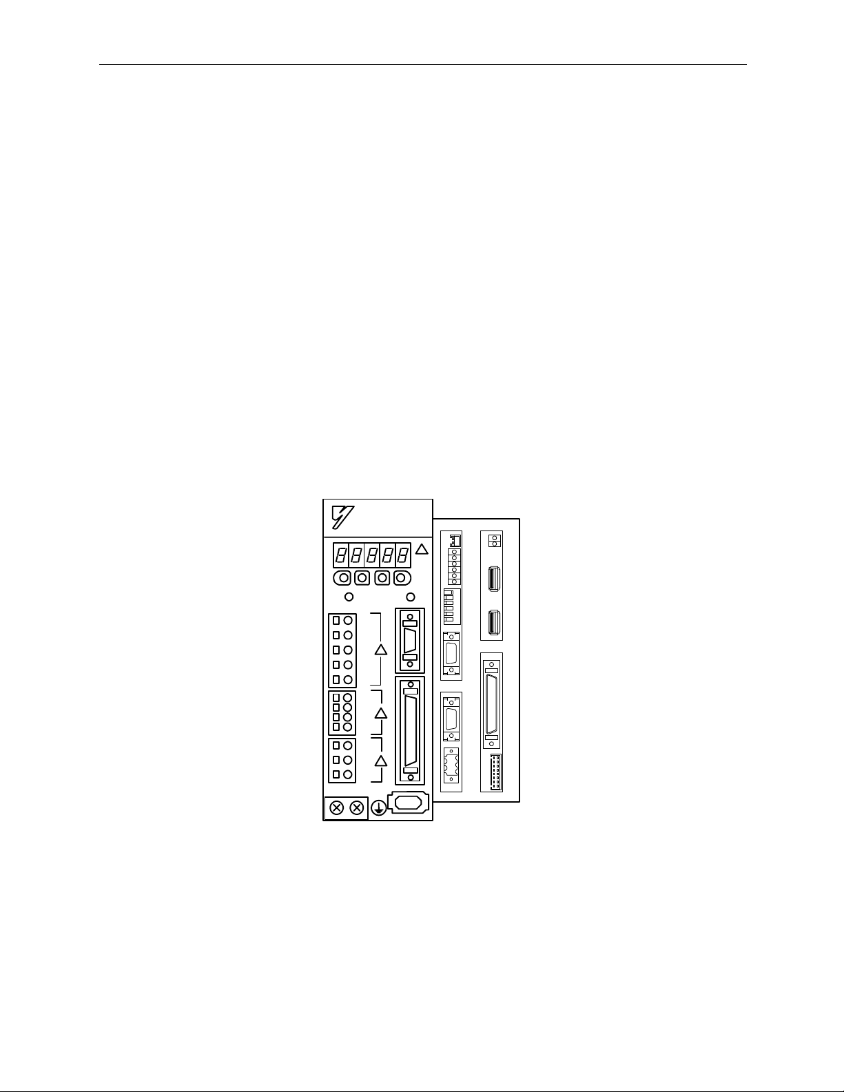
Exterior of the MP940 module
The MP940 is a single-axis controller with communication, local I/O,
external encoder, and motion functions bus connected with an SGDH servo
amplifier.
MP940
TX
BAT
R
X
RDY
RUN
ALM
1
BAT
L1
L2
L1C
L2C
B1
B2
PRT1
PRT2
RUN
654321
INIT
TEST
FLASH
PP
COPY
NO
・¨
PORT1
PORT2
POWER
+24V
GND
FG
M
E
C
H
A
T
R
2
O
L
I
N
K
I/O
LED
Figure 1.1: MP940 Machine Control and SGDH Servo Amplifier
1-1
Page 7
Outline of the MP940 MotionSuite™ MP940 Machine Controller Reference Manual
Features of the MP940
The MP940 machine controller functions in a variety of machine control
modes, from simple positioning to high-speed/high-precision synchronous
control.
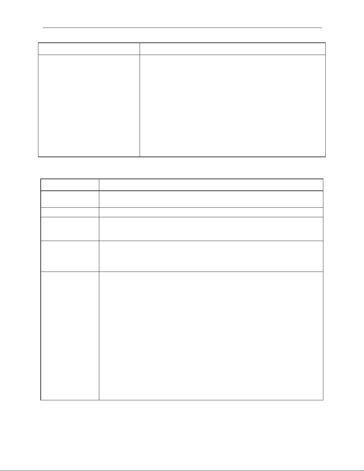
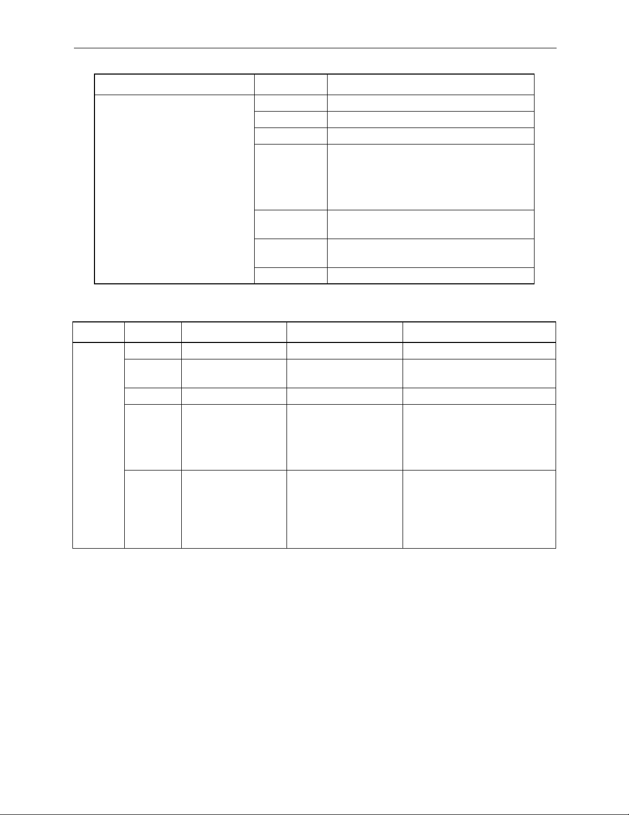
A single controller
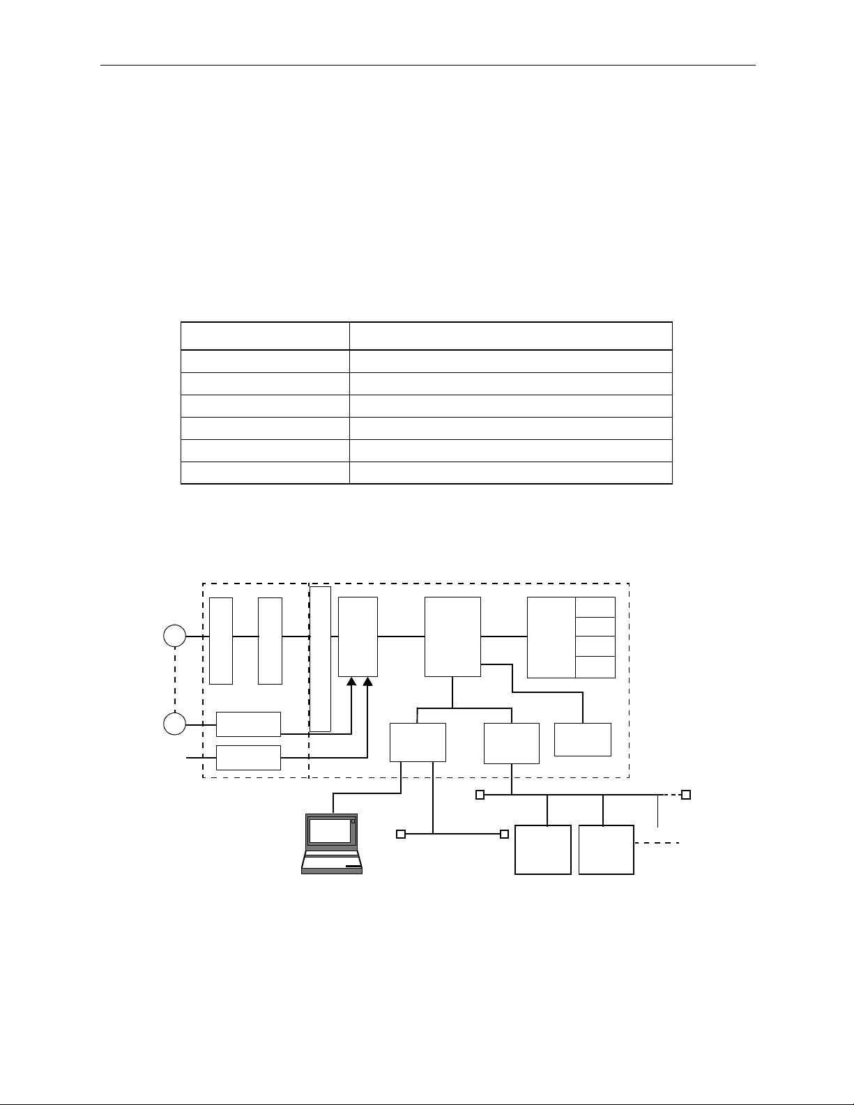
The MP940 is composed of the following modules.
Function Module Content
MP940 CPU
SERIAL Serial communication RS-232C, RS-422/485
LIO Control I/O, DI 8points, DO 8points, AO 1CH
SVA Motion function
CNTR Counter function
MLINK or DeviceNet Mechatrolink I/F function or DeviceNet I/F function
M
PG
AI
SGDH MP940
Current Control
Counter
Speed Control
A/D
DPRAM or Global Memory
Programming Device
Figure 1.2: MP940 Functions
SVA
RS-232C
.
SERIAL
RS-422/485
MP940
CPU
MLINK
or
DeviceNet
MLINK
Device 1
DeviceNet
Local
I/O
or
DI
DO
AO
AI
CNTR
MLINK
Device 2
1-2
Page 8
MotionSuite™ MP940 Machine Controller Reference Manual Outline of the MP940
Synchronized controller and servo amplifier
High-speed/high-prescision control is possible because the controller and
SGDH servo amplifier are bus connected. There is no lag in startup or
monitor time, and execution is accomplished in perfect synchronization.
The control period settings can be set to the following periods:
500 µs, 1 ms, 2 ms 4 ms
Reduced wiring/Smaller size
The combination controller/servo amplifier result in wiring reduction and
space savings.
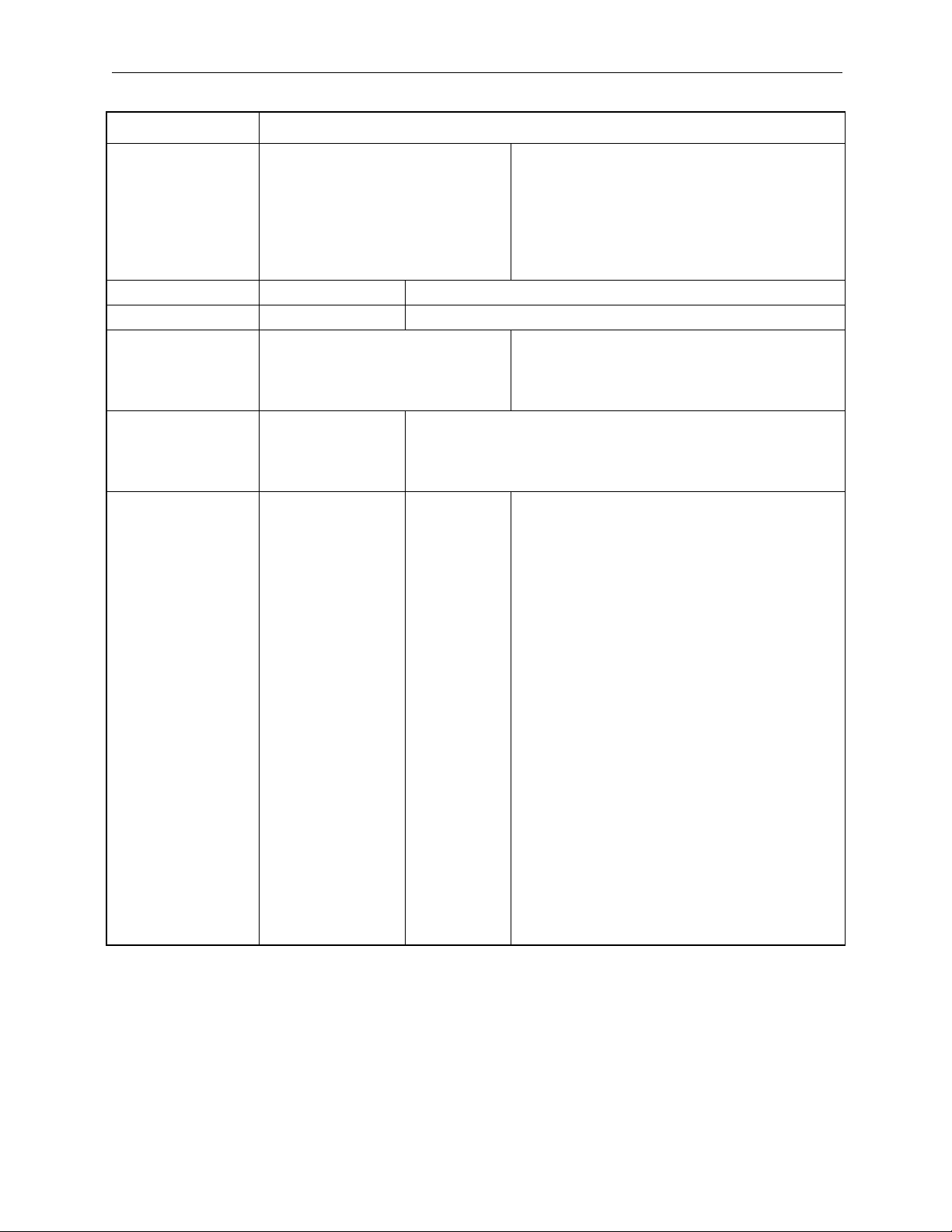
Variety of motion control modes, including:
• Positioning, linear interpolation motion program commands
• High-speed processing position/synchronous phase/speed control/torque
control
• Excellent for electronic shaft and electronic gear applications
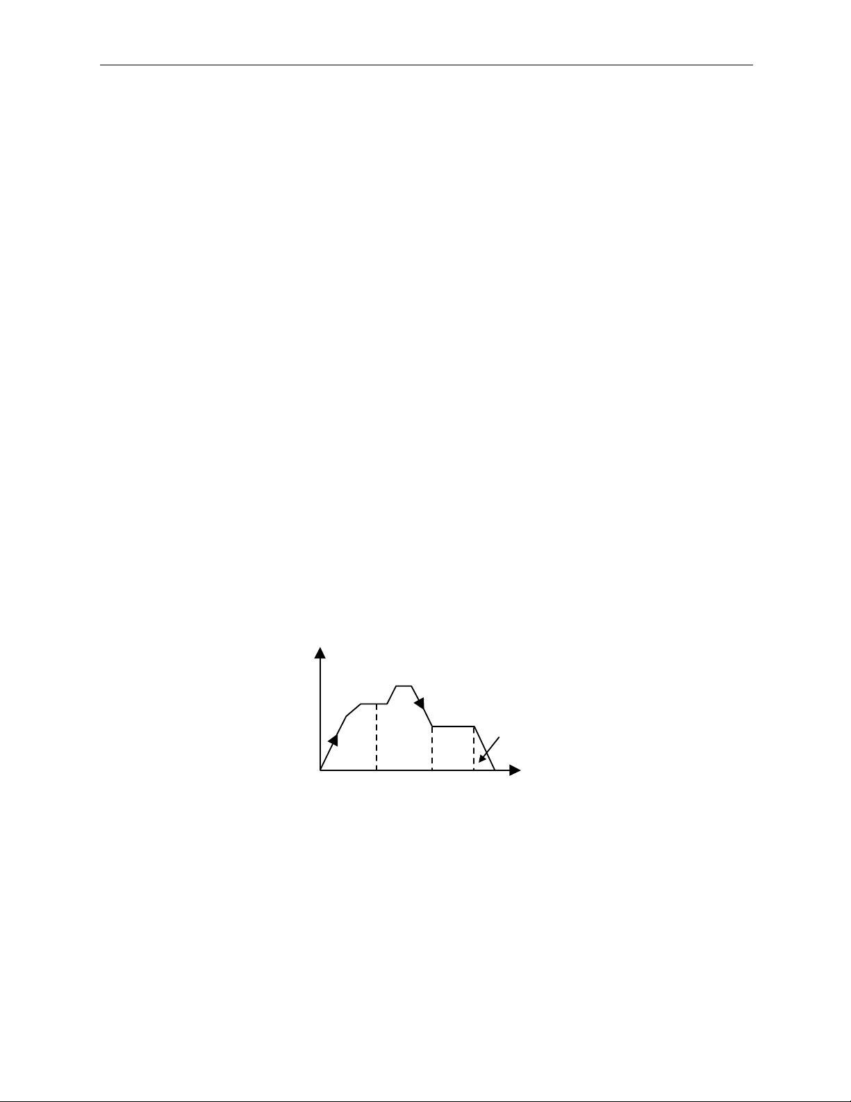
The four control modes (speed, synchronous phase, torque, and position) are
illustrated below..
V
Synchronous
Speed
Phase
Torque
Position
T
Figure 1.3 Four Control Modes
1-3
Page 9
Outline of the MP940 MotionSuite™ MP940 Machine Controller Reference Manual
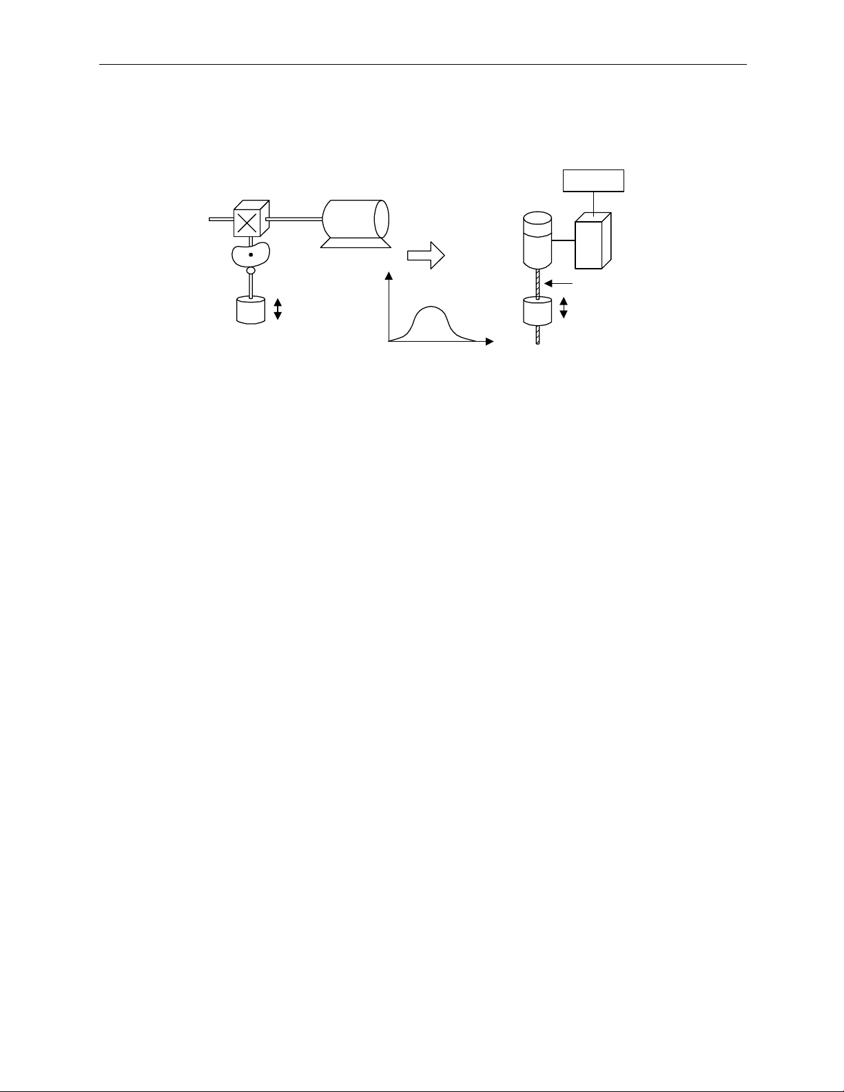
The following figure provides an example of a synchronous phase control
application.
MP920
Servo
Motor
X
Į
Servo
Amp.
Ball Screw
Figure 1.4: Electronic Camming
High-precision synchronous control
User parameter change is executed at high speed for monitor and servo
amplifier data. High-precision synchronous control is possible through the
READ/WRITE function of this data in both ladder and motion programs.
• Mode switching during operation
Switching between position control, torque control, speed control, and
synchronous phase control is possible during operation.
1-4
Page 10
MotionSuite™ MP940 Machine Controller Reference Manual Outline of the MP940
• Run commands
P/PI switching, external torque limit, and speed limit during torque control can be commanded from the MP940 during operation.
• READ/WRITE function of servo amplifier user parameters
User parameters such as Servo Amplifier Position Loop Gain, Speed
Loop Gain, Speed Loop Integral Time Constant, etc. may be modified
during operation.
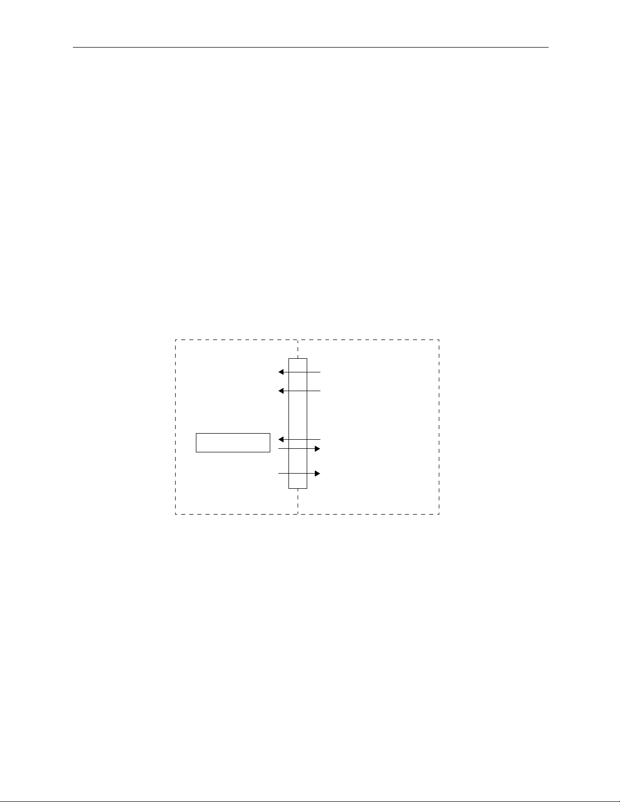
• Position data monitor
The various position data, reference speed, speed monitor, and external
encoder data can be referenced at high speed within the program, as
depicted below.
SGDH MP940
Global Memory or DPRAM
Speed Torq ue
Speed reference
Torque reference
Tor q ue li m it
Speed P/PI
Switching
User parameter
Various monitor data
• Position
• Speed
• Torque
Figure 1.5: Position data monitor
Mode switching command
Various run commands
User parameter
READ/WRITE
Monitor data reference
1-5
Page 11
MotionSuite™ MP940 Machine Controller Reference Manual Specifications and Functions
Chapter 2: Specifications
This chapter describes the general specifications and functions of the MP940.
Specifications and Functions
This section describes the general specifications and functions of the MP940.
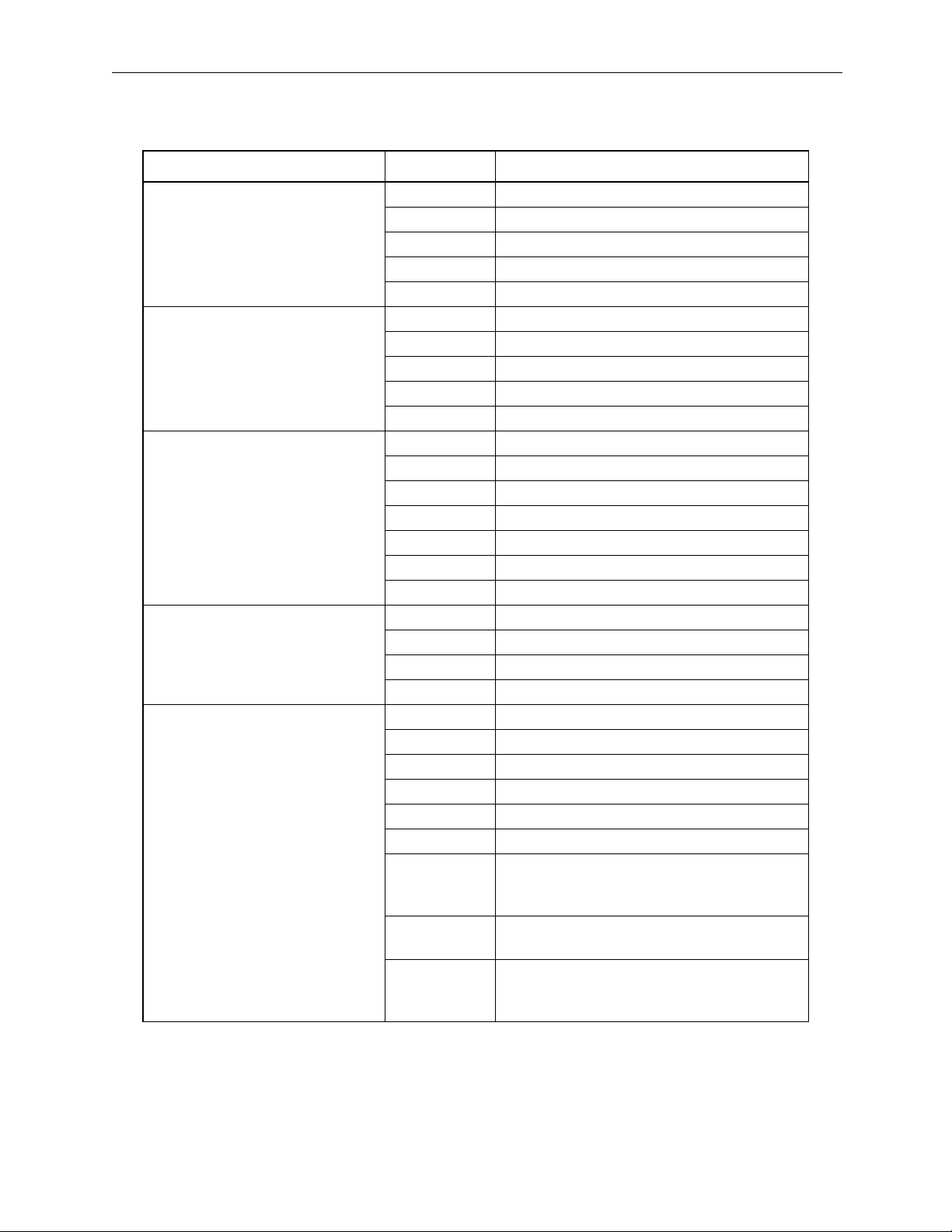
General Specifications
Item Specification
Ambient Usage Temperature 0 ~ +55ºC
Storage Temperature -20 ~ +85º
Ambient Usage Humidity 30 ~ 95% RH (no condensation)
Ambient Storage Temperature 5 ~ 95% RH (no condensation)
Pollution Level JIS B3501 standard pollution level 1
Corrosion Resistance No flammable or corrosive gas
Physical Environment
Usage Altitude less than 2000M above sea level
Noise Resistance JIS B3502 standard
Normal Mode 1500Vp-p
Common Mode 1500Vp-p
Pulse Width 100ns/ 1
Characteristics
Electrical Drive
Vibration Resistance JIS B3502 standard
Characteristics
Mechanical Drive
Shock Resistance JIS B3502 standard
Grounding
Cooling Method
Ground
Conditions
Boot-up time 1ns
(according to noise simulator)
Vibration Amplitude/Acceleration :
10
≤ f<57Hz Half-wave Amplitude 0.075mm
≤ f ≤150Hz set acceleration 9.8m/s
57
Scan in each of the X, Y, Z directions (1
octave/ min.)
× Number of scans 10
Peak Acceleration 147m/s
Twice in each direction ( X, Y, and Z)
Class 3 Grounding
Natural Cooling
2
2
work time 11ms
2-1
Page 12
Specifications and Functions MotionSuite™ MP940 Machine Controller Reference Manual
Hardware Specifications
Hardware Specifications
Item Specification
Name MP940 (Mechatrolink) MP940D (DeviceNet)
Model JEPMC-MC400 JEPMC-MC410
Memory FLASH 2MB
SRAM 2MB (battery backup)
Communication Port 1 RS-232C Port (Port1)
Baud Rate Setting 9.6k/19.2kbps
MDR-14 (dedicated pin assignment)
Protocol
• Memobus
• No Protocol
• Melsec Communication
1 RS-422/485 Port (Port2)
Baud Rate Setting 9.6k/19.2kbps
MDR-14 (dedicated pin assignment)
Protocol
• Memobus
•
No Protocol
• Melsec Communication
Network Baud rate: 4Mbps
Cycle: 1ms, 2ms, 4ms
Maximum # of Slaves: 6 @ 1ms, 14 @
2ms, 29 @4ms
Display LEDs Status Display LEDs
READY (Green)
RUN (Green)
ALM (Red)
BATALM (Red)
PRT1 (Green)
PRT2 (Green)
Mechatrolink Operation Display LEDs
RX (Green)
TX (Green)
Setting Switches DIP switches for mode setting
RUN/STOP
INITIAL
TEST
FLASH
PP_INIT
MREG_CPY
Baud rate: 125Kbps, 250 Kbps, 500Kbps
Mode: Slave
Node: 63 maximum
DeviceNet operation display LEDs
M9 (Red/Green)
N9 (Red/Green)
2-2
Page 13
MotionSuite™ MP940 Machine Controller Reference Manual Specifications and Functions
Hardware Specifications (Continued)
Item Specification
DeviceNet Setting Switch — DR0.DR1: Baud rate
DR0 DR1
OFF OFF 125Kbps
OFF ON 250Kbps
ON OFF 500Kbps
ON ON Do not use
X1: Slave/Master
X2: Reserved
Input Signals Number of Inputs: 8/Common
Input Type: Combined sink/source
Input Type: Type 1 (JIS-B3501)
Insulation Type: Photocoupler Insulation
Base Voltage: 17.4VDC ~ 28.8VDC
35VDC (at peak)
Rated Current: 5.3mA
Input Impedance: approximately 4.4kΩ
Operating Voltage: ON Voltage 15VDC or higher
OFF Voltage 5VDC or less
OFF Current: 0.9mA or less
Response Time: OFF
ON
Output Signals Number of Outputs: 8/Common
Output Type: Sinking Output
Output Type: Transistor Output
Insulation Type: Photocoupler Insulation
Load Voltage: 19.2 ~ 28.8V
35VDC (at peak)
Load Current: 0.1A/Circuit 0.8A/Common
ON Voltage: 1.0V or less
External Source Voltage: 24V
15mA
Output Protection:1 common fuse
Fuse Rating:1.5A (Fusing Time: 5s or less at 3A)
Response Time: OFF
ON
ON 0.5ms or less
OFF 1.5ms or less
DC
±20%
DC
ON 0.25ms or less
OFF 1ms or less
2-3
Page 14
Specifications and Functions MotionSuite™ MP940 Machine Controller Reference Manual
Hardware Specifications (Continued)
Item Specification
Pulse Input Pulse Input Circuit: 5V Deviation 1MHz input maximum
Pulse Input Circuit: A/B phase input (1×, 2×, 4× multiples can be selected)
AB Format, Sign Format, Add/Subtract Format
Pulse Counter Latch: (the external signal can be switched between 5V/12V/24V)
Analog Input SGDH Servo Amplifier
Analog Output Resolution:16-bit
Output Range: 0 ~ 10V
Power Input Input Signal: 24VDC ±20% (19.2VDC ~ 28.8VDC)
Input Current: 0.4A
Fuse Rating: 1.5A
Safety Criteria: UL, CSA standard
External Dimensions W44mm H142mm D128mm
2-4
Page 15
MotionSuite™ MP940 Machine Controller Reference Manual Specifications and Functions
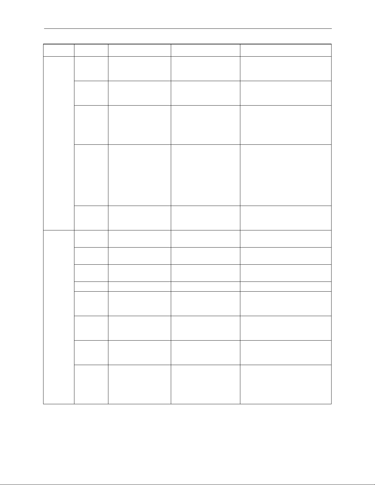
Function List
MP940 Motion Control Function Specificationss
Item Specification
Number of Control Axes 1
PTP Control Linear, Rotary, Unlimited
Interpolation Linear
Speed Reference Output Yes
Torque Reference Output Yes
Position Control Positioning, External Positioning, Zero-point Return, Interpolation,
Interpolation with position detection function, set feed speed, stepping
Phase Control Yes
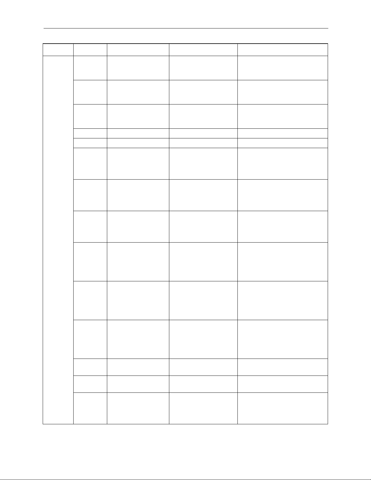
Contour Specifications
Command Unit mm, inch, degree, pulse
Minimum Command Set-
ting Unit
Maximum Command
Value
Speed Reference Unit mm / min., inch / min., deg / min., pulse / min.
Position Control
Acceleration Type Linear, Asymmetric, S-curve
Override Function 0.01 ~ 327.67%
Coordinates Linear Coordinates
Zero-point Return 8 Types
Language Dedicated motion language ladder
Number of Tasks A maximum of 8 parallel programs can be simultaneously executed.
Number of Programs 32 maximum
Properties
Program Capacity 80kb
Applied Servo Amplifier Analog Type: SGDH-**AE
Encoder Incremental/Absolute
Speed
Control
Speed Reference -327.68 ~ +327.67 %/Rated Speed
Acceleration Type Linear, asymmetric, S-curve (motion average)
Torque
Control
Phase
Control
Torque Reference -327.68 ~ +327.67 %/Rated Torque
Speed Reference Unit -327.68 ~ +327.67 %/Rated Speed
Speed Correction -327.68 ~ +327.67 %/Rated Speed
Position Correction -2147483648 ~ +2147483647 pulses
1, 0.1, 0.01, 0.001, 0.0001, 0.00001
-2147483648~+2147483647 (with 32-bit sign)
1. DEC1+C phase 5. DEC1+ZERO
2. DEC2+C phase 6. DEC2+ZERO
3. DEC1+LMT 7. DEC1+LMT+ZERO
4. C-phase 8. ZERO
With torque limit function
With speed limit function
2-5
Page 16
Specifications and Functions MotionSuite™ MP940 Machine Controller Reference Manual
Item Specification
Command Language Axis Motion Commands 5
MOV, MVS, ZRN, SKP, EXM
Basic Control Commands 5
ABS, INC, POS, MVM, PLD
Speed, Accel/decel commands 8
ACC, DCC, SCC, VEL, IAC, IDC, IFP, FMX
Upper-level Control Commands 4
PFN, INP, SNG, UFC
Control Commands 10
MSEE, TIM, IOW, END, RET, EOX, IF, ELSE, IEND, WHILE WEND,
SFORK, JOINTO, SJOINT
Operations/Sequence Control Commands 32
=, +, -, *, /, MOD, |, ^, &, !, (), S{}, R{}, SIN, COS, TAN, ASN, ACS,
ATN, SQRT, BIN, BCD, ==, <>, >, <, >=, <=, SFR, SFL, BLK, CLR
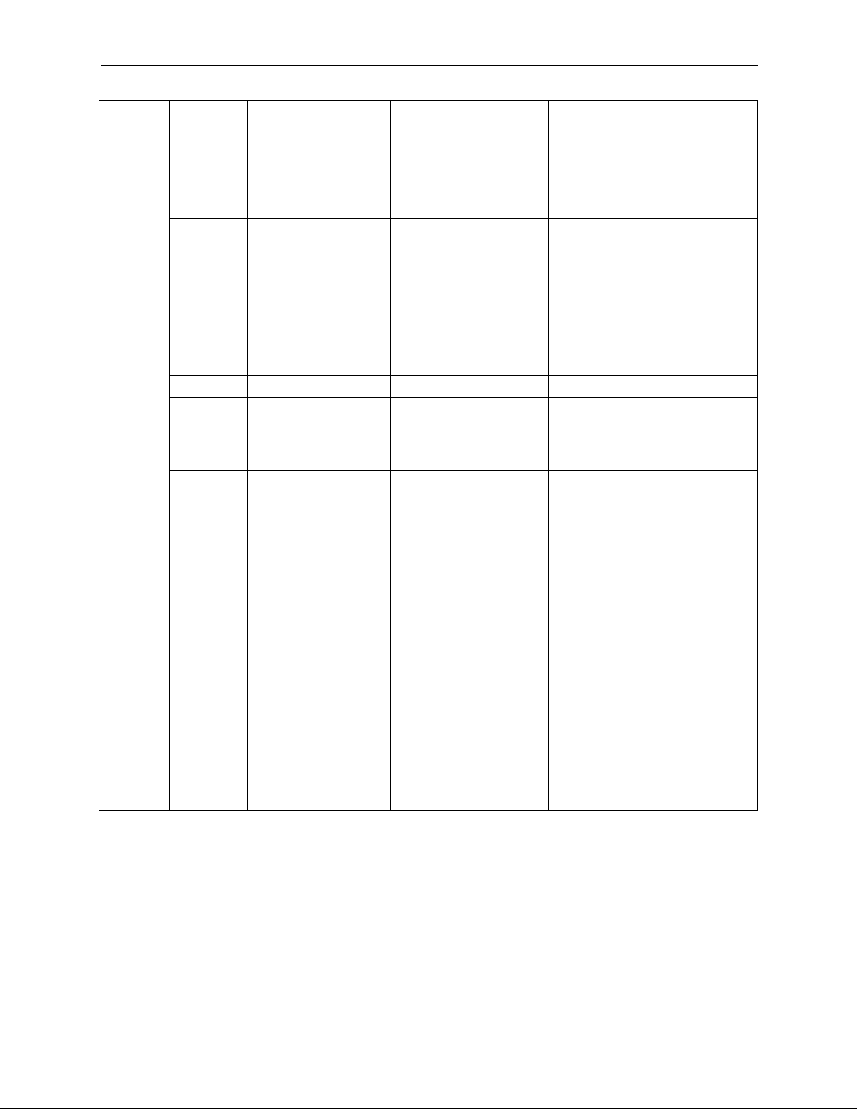
PLC Function Specifications
Item Specification
Program Capacity For every 2k steps (varies according to the size of the motion program. 40k steps
maximum)<H>
Control Format Sequence: Scan Format
Program Language CP Code
Ladder Diagram: Relay Circuit
Text-type language: Numerical operations, logical operations, etc.
Scan Servo Control Scan Time Setting: 0.5 / 1.0 / 2.0 / 4.0 ms
High-speed Scan Time Setting: 0.5 ~ 32.0ms (0.01ms units) S scan integer multiples
Low-speed Scan Time Setting: 2.0 ~ 200.0ms (0.01ms units) S scan integer multi-
ples
User Diagrams
Functions, Motion
Programs
Start Drawing (DWG.A):Maximum of 4 drawings, with up to 3 layers per drawing
System Scan Drawing (DWG.S): Maximum of 16 drawings, with up to 3 layers per
drawing
High-speed Scan
Drawing (DWG.H)
:Maximum of 16 drawings, with up to 3 layers
per drawing
Low-speed Scan
Drawing (DWG.L)
Interrupt Drawing (DWG.I)
Number of steps
User Functions
Motion Programs
Drawing, Motion Program Modification History
Drawing, Motion Program Secure Holding Function
2-6
:Maximum of 32 drawings, with up to 3 layers
per drawing
:Maximum of 8 drawings, with up to 3 layers per
drawing
:Maximum 500 steps/drawing
:Maximum 32 functions
:Maximum 32
Page 17
MotionSuite™ MP940 Machine Controller Reference Manual Specifications and Functions
Item Specification
Data Memory Global Data (M) Register
System (S) Register
DWG Local (D) Register
DWG Setting (#) Register
Input (I) Register
Output (I) Register
Constant (C) Register
Trace Memory Data Trace :4k words (4k words × 1 group)
Memory Backup Program Memory :CMOS Battery Backup
Data Type Bit (Relay)
Integer
Double-length Integers
Real Numbers
Register Attribute Register Number
Designation
Symbol Designa-
tion
Command Lan-
guage
Program Control
Commands
During Direct I/O
Commands
Relay Circuit Com-
mands
Logical Operation
Commands
Numerical Opera-
tion Commands
Numerical Conver-
sion Commands
Numerical Compar-
ison Commands
Data Operation
Commands
Basic Function
Commands
Display Data Oper-
ation Commands
DDC Commands
System Functions
: Direct Register Number Designation
: A maximum of 8 alphanumeric characters. (
200 symbols/DWG maximum) Autonumbering and autosymbols available
:14
: 2
:14 (including
set, reset
coils)
: 3
:16
: 9
: 7
:14
:10
:11
:13
:9
: 32 kwords
: 1 kwords
: Maximum 16 words/DWG
: Maximum 16 words/DWG
: 2 kwords (including internal input register)
: 2 kwords (including internal output register)
: 32 kwords
: ON/OFF
: -32768 ~ +32767
: -2147483648 ~ 2147483648
: ±(1.175E-38 ~ 3.402E+38)
Command Language
2-7
Page 18
Specifications and Functions MotionSuite™ MP940 Machine Controller Reference Manual
Motion Command List
Command Language Types Commands Function
Axis Motion Commands MOV Positioning
MVS Linear Interpolation
ZRN Zero-point return
SKP Skip command
EXM External Positioning
Basic Control Commands ABS Absolute mode
INC Incremental mode
POS Current Variation
MVM Machine Coordinate Designation
PLD Program Current Position Update
Speed/Acceleration Commands ACC Acceleration Time Change
SCC S-curve Parameter Change
VEL Feed Speed Change
IAC Interpolation Acceleration Time Change
IDC Interpolation Deceleration Time Change
IFP Interpolation Feed Speed Ratio Setting
FMX Interpolation Feed High-speed Setting
Upper-level Control Commands PFN In-position Check
INP 2nd in-position check
SNG Ignore Single Block
UFC User Function Call-out
Control Commands MSEE Sub-program Call-out
TIM Timed Wait
IOW I/O Variable Wait
END Program Close
RET Sub-program Close
EOX 1 scan WAIT command
IF
ELSE
IEND
WHITE
WEND
SFORK
JOINTO
SJOINT
Branching Commands
Repetition Commands
Selection Execution Commands
2-8
Page 19
MotionSuite™ MP940 Machine Controller Reference Manual Specifications and Functions
Command Language Types Commands Function
Sequence Commands = Replacement
+, -, ×, /, MOD Numerical Operations
|, ^, &, ! Logical Operations
SIN, COS,
TAN, ASN,
ACS, ATN,
SQRT, BIN,
BCD
==, <>, >, <,
>=, <=
SFR, SFL,
BLK, CLR
(), S{}, R{} Other
Function Commands
Numerical Comparison Commands
Data Operation
Motion Command List
Type Command Name Command Format Function/Meaning
MOV Positioning MOV [axis1]—; * Executes fast feed positioning.
MVS Linear Interpolation MVS [axis1]—F; Executes linear interpolation at
interpolation feed speed F.
ZRN Zero-point return ZRN [axis1] ; Returns to zero-point.
SKP Skip Command SKP [axis1]SSF; When turned on during linear
interpolation execution, the
machine skips the remaining
motion and proceeds onto the
next block.
EXM External Positioning EXM [axis1] D; Upon input of an external posi-
Axis Motion Commands
tioning signal during positioning
execution, the machine pro-
ceeds to the next block after
positioning only in increments of
the motion designated in “D”.
2-9
Page 20
Specifications and Functions MotionSuite™ MP940 Machine Controller Reference Manual
Type Command Name Command Format Function/Meaning
ABS Absolute mode ABS; The following coordinate
expressions are handles as
absolute values.
INC Incremental mode INC: The following coordinate
expressions are handles as
incremental values.
POS Current Variation POS [axis1]; Changes the current value to a
desired coordinate.Subsequent
motion commands execute
motion on the basis if the new
coordinates.
MVM Machine Coordinate
Command
Basic Control Commands
PLD Program Current
Position Update
ACC Acceleration Time
Change
DCC Deceleration Time
Change
SCC S-curve Parameter
Change
VEL Feed Speed Change VEL [axis1] ; Sets feed speed.
IAC Interpolation
Acceleration Time
Change
IDC Interpolation
Deceleration Time
Change
IFP Interpolation Feed
Speed Ratio Setting
Speed/Accel/Decel Commands
FMX Interpolation Feed
High-speed Setting
MVM MOV [axis1];
or
MVM MVS [axis1];
PLD [axis1] ; Updates the current position of
ACC [axis1]; Sets the acceleration time for
DCC [axis1]; Sets the deceleration time for
SCC [axis1]; Sets parameters during motion
IAC T; Sets acceleration time for linear
IDC T; Sets deceleration time for linear
IFP P; Executes speed designation
FMX T; Sets the maximum speed during
These commands are issued
when motion is desired based
on the machine coordinate.The
coordinates automatically set at
zero-point return completion are
called the machine coordinates.These coordinates are not
affected by POS commands.
a program shifted by manual
feed, etc.
linear acceleration
linear acceleration
average accel/decel.
accel/decel during interpolation
motion.
accel/decel during interpolation
motion.
during interpolation feed in % of
maximum speed.
interpolation feed.
This is the time taken in interpolation acceleration to go from
zero to this speed.
2-10
Page 21

MotionSuite™ MP940 Machine Controller Reference Manual Specifications and Functions
Type Command Name Command Format Function/Meaning
/ Division MW = MW / MW;
MW = MW / 123456;
MW = 123456 / MW;
MOD Modulus MW = MW / MW;
MW = MOD;
| OR (Logical OR) MB = MB | MB;
MB = MB | 1;
MW = MW | MW;
MW = MW | H00FF;
^XOR
(Exclusive Logical
OR)
& AND (Logical AND) MB = MB & MB;
! NOT (Inversion) MB = !MB;
() Parentheses MW = MW— &
S{} Designated bit ON S{MB} = MB & MB; The designated bit goes ON if
Sequence Commands
R{} Designated bit OFF R{MB} = MB & MB; The designated bit goes OFF if
SIN Sine SIN(MW)
COS Cosine COS(MW)
TAN Tangent TAN(MF)
ASN Arc Sine ASN(MF)
MW = MW ^ MW;
MW = MW ^ H00FF;
MB = MB & 1;
MW = MW & MW;
MW = MW & H00FF;
MB = !1;
MW = !MW;
MW = !H00FF;
(MW— | MW—);
;SIN(90);
;COS(90);
;TAN(45.0);
;ASN(90.0);
Executes integer/real number
division.Operates as real numbers when integers and real
numbers are intermixed.
MOD is stored as a modulus
into a designated register when
designated in the next block of
the modulus.
Creates a logical OR in bits or
integers.
Creates an exclusive logical OR
in integers.
Creates a logical AND in bits or
integers.
Creates an inverse value in bits.
Logical operations within parentheses have priority.
the logical operation result is
“Valid”.The designated bit goes
OFF when the result of a logical
operation is “Invalid”.
the logical operation result is
“Valid”.The designated bit goes
ON when the result of a logical
operation is “Invalid”.
Obtains the sine in integers/real
numbers (deg), and returns a
real number value.
Obtains the cosine in integers/
real numbers (deg), and returns
a real number value.
Obtains the tangent in real numbers (deg), and returns a real
number value.
Obtains the arc sine in real numbers, and returns a real number
value.
2-11
Page 22
Specifications and Functions MotionSuite™ MP940 Machine Controller Reference Manual
Type Command Name Command Format Function/Meaning
ACS Arc Cosine ACS(MF)
;ACSi_90.0);
ATN Arc Tangent ATN(MW)
;ATNi_45j_;
SQT Square Root SQT(MW)
;SQT(100);
BIN BCD¨_BIN BIN (MW); Converts BCD data to BIN data.
BCD BIN¨_BCD BCD (MW); Converts BIN data to BCD data.
== Coincidence IF MW == MW;
WHILE MW == MW ;
<> Non-coincidence IF MW <> MW;
WHILE MW <> MW;
> Larger than IF MW > MW;
WHILE MW > MW;
< Smaller than IF MW < MW;
WHILE MW < MW;
Sequence Commands
>= Equal to or greater
than
<= Equal to or less than IF MW <= MW;
SFR Right Shift SFR MB N W; Shifts the word variables to the
SFL Left Shift SFL MB N W; Shifts the word variables to the
BLK Block Transfer BLK MW MW W; Treats a designated bit (word)
IF MW >= MW;
WHILE MW >= MW;
WHILE MW <= MW;
Obtains the arc cosine in real
numbers, and returns a real
number value.
Obtains the arc tangent in integers/real numbers, and returns
a real number value (deg).
Obtains the square root in integers/real numbers (deg), and
returns a real number value.
Used in the IF or WHILE condition formula.The formula is
assumed to be “Valid” if the left
and right sides coincide.
Used in the IF or WHILE condition formula.The formula is
assumed to be “Valid” if the left
and right sides do not coincide.
Used in the IF or WHILE condition formula.The formula is
assumed to be “Valid” if the left
side is larger than the right side.
Used in the IF or WHILE condition formula.The formula is
assumed to be “Valid” if the left
side is smaller than the right
side.
Used in the IF or WHILE condition formula.The formula is
assumed to be “Valid” if the left
side equal to or greater than the
right side.
Used in the IF or WHILE condition formula.The formula is
assumed to be “Valid” if the left
side equal to or less than the
right side.
right by an exponent.
left by an exponent.
variable as opened, and executes transfer by block (parameter designation) unit.
2-12
Page 23
MotionSuite™ MP940 Machine Controller Reference Manual Specifications and Functions
Type Command Name Command Format Function/Meaning
CLR Clear CLR MB W; The parameter designator num-
ber goes OFF (0) for a variable
group in which the designated
bit (word) variables are
assumed to be started.
MSEE Sub-program Call-out MSEE MPS ; Executes MPS sub-program.
TIM Timed Wait TIM T; Waits for the time designated in
“T”, and proceeds to the next
block.
IOW I/O Variable Wait IOW MB == ∗∗∗; Stops motion control program
execution until the conditional
formula is satisfied.
END Program Close END; Closes the motion program.
RET Sub-program Close RET; Closes the sub-program.
EOX 1 scan WAIT com-
mand
EOX; This command is for cutting into
a continuing sequence com-
mand during operation, and
forcing a single scan wait.
(Process 1) is performed if the
conditional formula is satisfied,
and (process 2) if it is not.
Control Commands
IF
ELSE
IEND
Branching Commands
IF (conditional formula);
(process 1)
ELSE;
(process 2)
IEND;
WHILE
WEND
SFORK
JOINTO
SJOINT
Repetition Commands
Selection Execution
Commands
WHILE (conditional
formula);
•••
WEND;
SFORK conditional formula 1? label 1,
conditional formula 2?
label 2, •••;
label 1: Process 1
JOINTO label
xlabel 2: Process 2
JOINTO label
xlabel •
•label x: SJOINT;
Repeats execution of
WHILE~WEND processing the
conditional formula is satisfied
and continues operating.
(Process 1) is performed if the
conditional formula 1 is satis-
fied, and (process 2) if condi-
tional formula 2 is satisfied.
The “—” symbol in MOV [axis1]— •••; signifies where the numerical data for [axis1] is recorded.
2-13
Page 24
Specifications and Functions MotionSuite™ MP940 Machine Controller Reference Manual
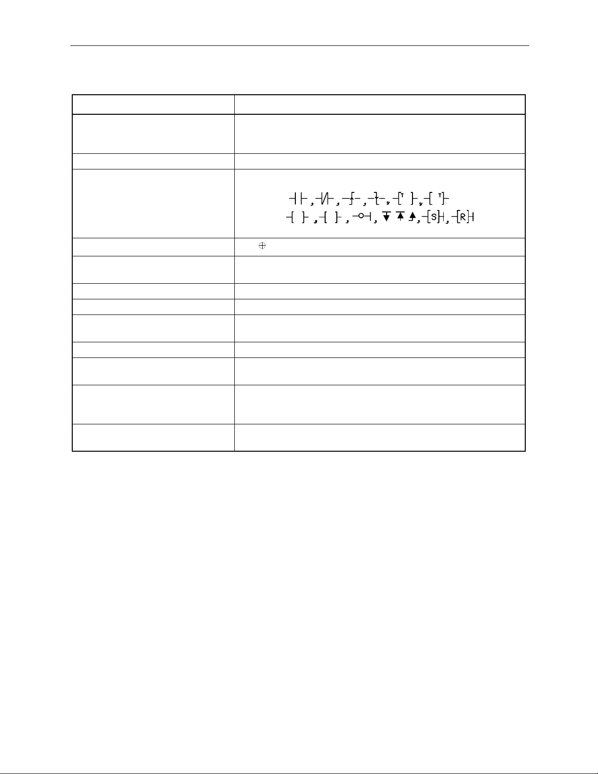
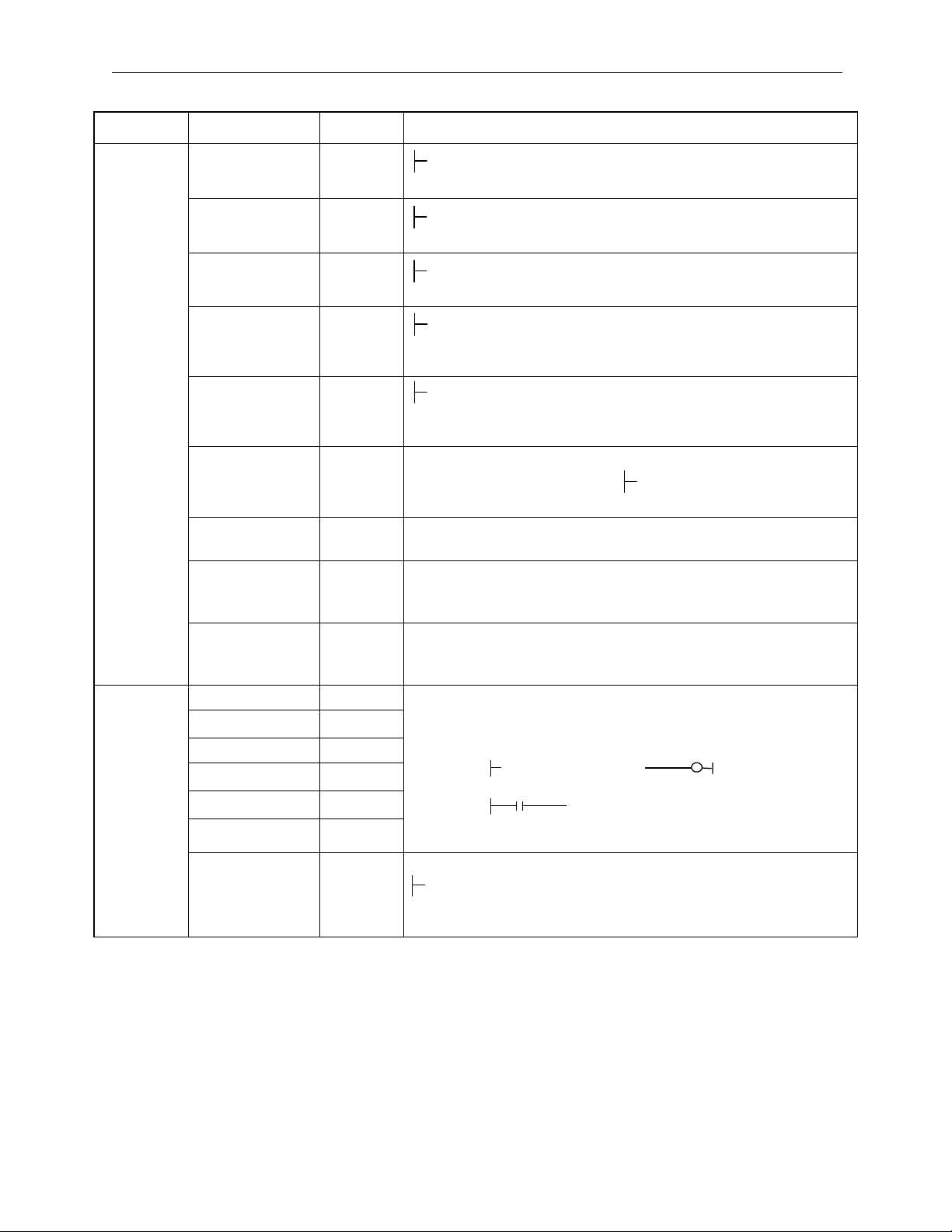
Ladder Command List
Command Language Types Symbol
Program Control Command SEE, FOR FEND, WHILE ON/OFF WEND
, IFON/IFOFF ELSE IEND, DEND
FSTART, FIN, FOUT, XCALL, comment
Direct I/O Commands INS, OUTS
Relay Circuit Commands
Ts
Ts
TsTs
Ts
Ts
TsTs
Logical Operation Commands
∧, ∨,
Numerical Operation Commands +, -, ++, --, ×, ÷, INC, DEC, MOD, REM,
TMADD, TMSUB, SPEND
Numerical Conversion Commands INV, COM, ABS, BIN, BCD, PARITY, ASCII, ASCBIN, BINASC,
Numerical Comparison Commands <,
≤, ≠, ≥, >, RCHK
Data Operation Commands ROTL, ROTR, MOVB, MOVW, XCHG, SETW, BETD, BPRESS,
BSRCH, SORT, SHFTL, SHFTR, COPYW, BSWAP
Basic Function Commands SQRT, SIN, COS, TAN, ASIN, ACOS, ATAN, EXP, LN, LOG
DDC Commands DZA, DZB, LIMIT, PI, PD, PID, LAG, LLAG,
FGN, IFGN, LAU, SLAU, PWM
Display Data Operation Commands TBLBR, TBLBW, TBLSRL, TBLSRC, TBLCL
TBLMV, QTBLR, QTBLRI, QTBLW, QTBLWI
QTBLCL
System Functions COUNTER, FINFOUT, TRACE, DTRC-RD, MSG-SND, MSG-
RCV
2-14
Page 25
MotionSuite™ MP940 Machine Controller Reference Manual Specifications and Functions
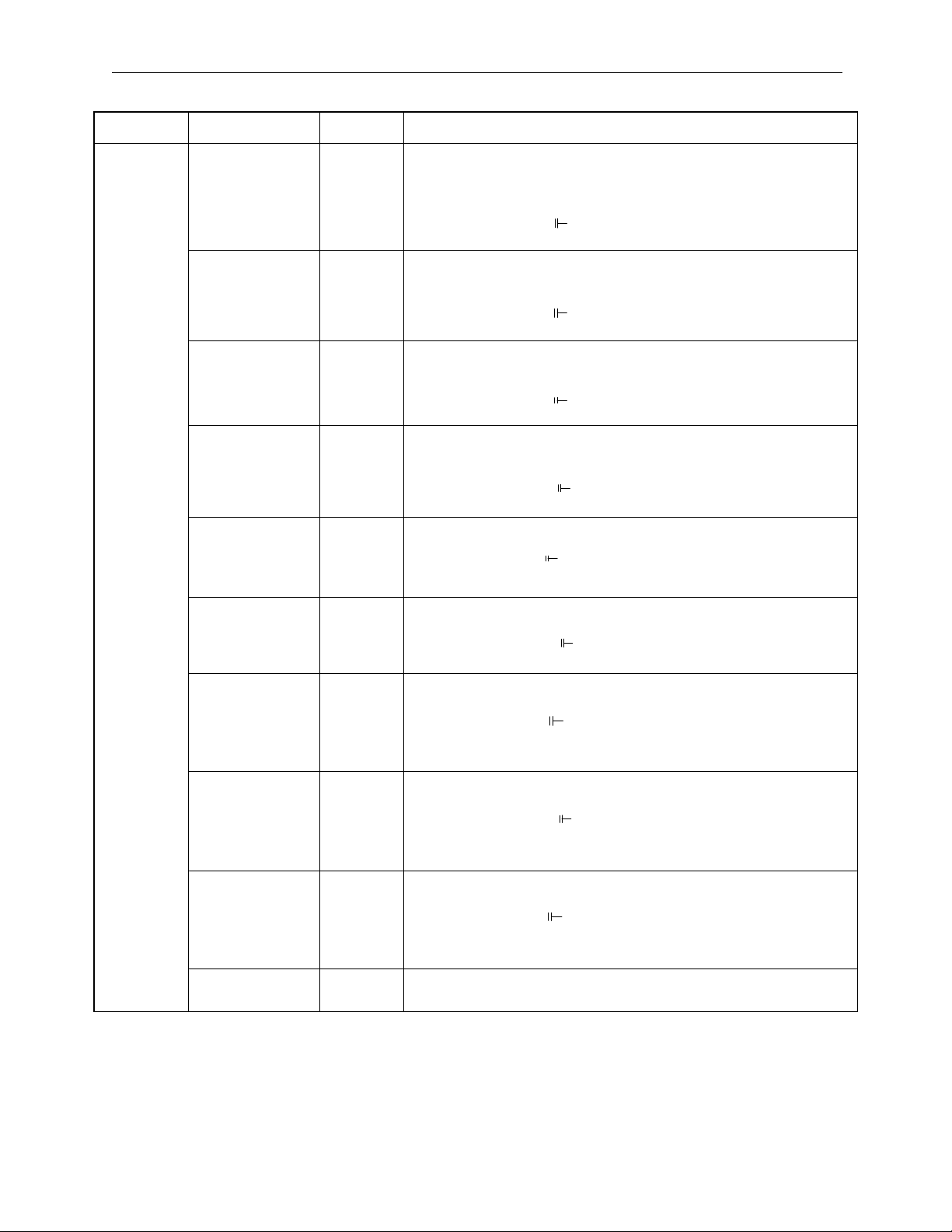
Ladder Command List
Type Name Symbol Content
Program Control Commands
Direct I/O
Commands
Sub-program
Reference
SEE After “SEE”, designate the sub-program, or sub-sub-program
number to be referenced.
SEE H01
Motion Drawing
Reference
MSEE After “MSEE”, designate the motion program number or status
work address to be referenced.
MSEE MPM001 DA00000
FOR expression FOR
:
:
FEND
Repeat Execution Expression 1
FOR V = a to b by c
V : Either integer register I or J may be designated as desired.
a, b, c :Any desired integer value can be designated (b>a>0,
c>0)
FEND:END of FOR command
WHILE
expression
WHILE
:
Repeat Execution Expression 2
WEND:END of WHILE-ON/OFF command
ON/OFF
:
WEND
IF expression IFON/
IFOFF
Execution expression with conditions
IEND:END of IFON/IFOFF command
:
ELSE
:
IEND
Drawing END DEND END of drawing (DWG)
Comments
“nnnnnnn” Characters surrounded by quotation marks (“ “) are treated as
comments.
Function I/F
FSTART Function Reference Command
FIN Function Input Command
Saves input data from a designated input register to the function
input register.
FOUT Function Output Command
Saves output data from a designated output register to the func-
tion output register.
XCALL Extended Program Reference Command
Input Commands INS INS MA00100 ————————|
Executes data input and storage by interrupt prohibit.
Output Commands
OUTS
OUTS MA00100 ————————|
Executes data setting and output by interrupt prohibit.
2-15
Page 26
Specifications and Functions MotionSuite™ MP940 Machine Controller Reference Manual
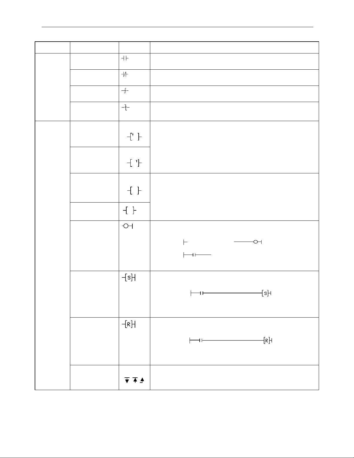
Type Name Symbol Content
A Contact No limit on series circuits
All register bit types can be designated as relay numbers.
B Contact No limit on series circuits
All register bit types can be designated as relay numbers.
Rising Edge
Pulse
Falling Edge
Pulse
No limit on series circuits
All register bit types can be designated as relay numbers.
No limit on series circuits
All register bit types can be designated as relay numbers.
Relay Circuit Commands
ON Delay Timer
(10ms)
Setting count register
Setting = all registers, parameters (setting unit: 10ms)
Count register = registers M,D
OFF Delay Timer
(10ms)
ON Delay Timer
(1s)
OFF Delay Timer
(1s)
Coil
Setting Coil
Relay Circuit Commands
Reset Coil
Setting count register
Ts
Ts
Setting = all registers, parameters (setting unit: 1s)
Count register = registers M,D
MB000000
MW0200 = 0001
MB000000
IFON
MB000010MB000000
MB000010 is ON when MB000000 is ON. Subsequently, ON is
obtained even if MB000000 goes OFF.
MB000010MB000020
Branching/
Joining
MB000020 is ON when MB000010 is OFF. Subsequently, OFF
is obtained even if MB000020 goes OFF.
All of the above relay commands can be connected to branching/
joining symbols.
2-16
Page 27
MotionSuite™ MP940 Machine Controller Reference Manual Specifications and Functions
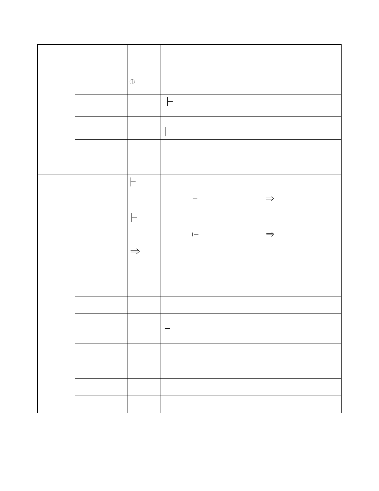
Type Name Symbol Content
Logical AND ∧ All registers and parameters can be designated in integer form.
Logical OR ∨ All registers and parameters can be designated in integer form.
Exclusive
All registers and parameters can be designated in integer form.
Logical OR
Addition +
Normal numerical addition (with operation error generation)
MW00280 +00100 ⇒ MW00220
Subtraction - Normal numerical subtraction (with operation error generation)
MW00280 -00100 ⇒ MW00220
Logical Operation Commands
Extended
Addition
Extended
Subtraction
Integer
++ Adds closed values (no operation error generation)
0¨→ 32767¨→ -32768¨→ 0
-- Subtracts closed values (no operation error generation)
0~-32767, -32768~0
Integer Operation Start
Replacement
Numerical Operation Commands
MW00220
Real Number
MW00280 + 00100
Real Number Operation Start
Replacement
MW00280 + 00100
MW00220
Storage Stores operation results to a designated register.
Multiplication × Used with × and ÷ in combination for integers and double-length
Division ÷
integers.
Increment INC Adds 1 to a designated register.
INC MW00100
Decrement DEC Subtracts 1 from a designated register.
DEC MW00100
Integer Remain-
MOD Obtains the remainder from the results of division.
der
MW00100 × 01000 ÷ 00121
MOD ⇒ MW00101
Real Number
Remainder
REM Obtains the remainder from the results of division.
MF00200 REM 1.5 ⇒ MF00202
Time Addition TMADD Addition of Hr/Min/Sec
TMADD MW00000, MW00100
Time Subtraction TMSUB Subtraction of Hr/Min/Sec
TMSUB MW00000, MW00100
Time Spent SPEND Requests the elapsed time for two time measures.
SPEND MW00000, MW00100
2-17
Page 28
Specifications and Functions MotionSuite™ MP940 Machine Controller Reference Manual
Type Name Symbol Content
Numerical Conversion Commands
Sign Inversion INV
MW00100 INV
Operation result = -99 when MW00100=99
Complement of 1 COM
MW00100 CON
Operation result = 0000H when MW00100= FFFFH
Absolute Conversion
Binary Conversion
BCD Conversion BCD
ABS
BIN
MW00100 ABS
Operation result = 99 when MW00100= -99
MW00100 BIN
Operation result = 1234 (decimal) when MW00100 = 1234H (hexadecimal)
MW00100 BCD
Operation result = 1234H (hexadecimal) when MW00100 = 1234
(decimal)
Parity Conversion
PARITY Calculates the number binary expression bits ON.
The operation result = 8 when MW00100 PARITYMW00100
= F0F0H
ASCII Conversion 1
ASCII Conversion 2
ASCII Converts a designated character string into ASCII, and replaces
it into the register ASCII MW00200 “ABCDEFG”
BINASC Converts 16-bit binary data into four hexadecimal digits in ASCII
code.
BINASC MW00100
ASCII Conversion 3
ASCBIN Converts numbers displayed as four hexadecimal digits in ASCII
code into 16-bit binary data.
ASCBIN MW00100
<<
Leaves the results of the comparison command ON or OFF in the B register.
≤≤
==
≠≠
≥≥
>>
MB000010
MW00000 < 10000
MB000010
IFON
Range Check
RCHK Checks whether the A register value is within range.
MW00100 RCHK -1000, 1000
Numerical Comparison Commands
2-18
Page 29
MotionSuite™ MP940 Machine Controller Reference Manual Specifications and Functions
Type Name Symbol Content
Right Bit Rotation ROTR Bit-addr Count Width
ROTR MB00100A ¨_ N=1 W=20
Bit Transfer MOVB Source Destination. Width
MOVB MB00100A ¨_ MB00200A W=20
Word Transfer MOVW Source Distribution. Width
MOVW MB00100 ¨_ MB00200 W=20
Replacement
Transfer
XCHG Source1 Source2 Width
XCHG MB00100 ¨_ MB00200 W=20
Data Initialization SETW Destination. Data Width
SETW MW00200 D=00000 W=20
Byte
_
Word Display
Word
_
Byte Compression
BEXTD Displays byte data stored into the word register area as words.
BEXTD MW00100 to MW00200 B=10
BPRESS Concatenates lower-level bytes of word data stored into the word
register area as words.
BPRESS MW00100 to MW00200 B=10
Data Scan BSRCH Searches within a designated register range for register positions
coinciding to the data.
BSRC MW00000 W=20 D=100 R=MW00100
Data Operation Command
Sort SORT Sorts the register within a designated register range.
SORT MW00000 W=100
Left Shift SHFTL Shifts a designated bit queue to the left.
SHFTL MB00100A N=1 W=20
Bit Right Shift SHFTR Shifts a designated bit queue to the right.
SHFTR MB00100A N=1 W=2
Word Copy COPYW Copies a designated register range.
COPYW MW00100 ¨_ MW00200 W=20
Byte Swap BSWAP Swaps the upper and lower-level bytes of designated word vari-
ables.
BSWAP MW00100
2-19
Page 30
Specifications and Functions MotionSuite™ MP940 Machine Controller Reference Manual
Type Name Symbol Content
Square Root SQRT The square roots of negative values are the square roots of the
absolute value multiplied by -1.
MF00100 SQRT
Sine SIN Input = degrees
MF00100 SIN
Cosine COS Input = degrees
MF00100 COS
Tangent TAN Input = degrees
MF00100 TAN
Arc Sine ASIN
MF00100 ASIN
Arc Cosine ACOS
MF00100 ACOS
Basic Function Commands
Arc Tangent ATAN
MF00100 EXP
MF00100
MF00100
MF00100MF00100
e
Exponent EXP
MF00100 LN
loge(FM00100)
Naturalized
Logarithm
LN
MF00100 LOG
log10(FM00100)
Common
Logarithm
LOG
2-20
Page 31

MotionSuite™ MP940 Machine Controller Reference Manual Specifications and Functions
Type Name Symbol Content
Dead Zone A DZA
Dead Zone B DZB
Upper Limit LIMIT
PI Control PI
PD Control PD
PID Control PID
First-order Lag LAG
Phase Lead/Lag LLAG
Function
DDC Commands
Generator
Inverse Function
FGN
IFGN MW00100 IFGN MA00200
MW00100 DZA 00100
MW00100 DZB 00100
MW00100 LIMIT -00100 00100
MW00100 PI MA00200
MW00100 PD MA00200
MW00100 PID MA00200
MW00100 LAG MA00200
MW00100 LLAG MA00200
MW00100 FGN MA00200
Generator
Linear
LAU MW00100 LAU MA00200
Accelerator 1
Linear
SLAU MW00100 SLAU MA00200
Accelerator 2
Pulse Width
PWM MW00100 PWM MA00200
Modulation
2-21
Page 32

Specifications and Functions MotionSuite™ MP940 Machine Controller Reference Manual
Type Name Symbol Content
Block Write TBLBR TBLBR TBL1, MA00000, MA00100
Block Read TBLBW TBLBW TBL1, MA00000, MA00100
Row Search (Ver-
TBLSRL TBLSRL TBL1, MA00000, MA00100
tical)
Column Search
TBLSRC TBLSRC TBL1, MA00000, MA00100
(Horizontal)
Block Clear TBLCL TBLCL TBL1, MA00000
Block Move TBLMV TBLMV TBL1, TBL2, MA00000
Queue Table
QTBLR QTBLR TBL1, MA00000, MA00100
Read
(invariable
pointer)
Queue Table
QTBLRI QTBLRI TBL1, MA00000, MA00100
Read
(pointer stepping
QTBLW QTBLW TBL1, MA00000, MA00100
Display Data Operation Commands
Queue Table
Write
(invariable
pointer)
Queue Table
QTBLWI QTBLWI TBL1, MA00000, MA00100
Write
(pointer stepping
Queue Pointer
QTBLCL QTBLCL TBL1
Clear
First-in
FINFOUT First-in/First-out
First-out
Trace Function TRACE Data Trace Execution Control
Data Trace Read DTRC-RD Data read from data trace memory into the user memory.
Message
MSG-SND Send message from controller.
Send
System Functions
Message
MSG-RCV Receive message from controller.
Receive
2-22
Page 33

MotionSuite™ MP940 Machine Controller Reference Manual Specifications and Functions
Servo Amplifier Specifications
External Appearence and Nameplate
Servo amplifier model
サーボパック形式
YASKAWA
SERVOPACK
SGDH-
SGDH-
SGDH-SGDH-
MODE/SET
DATA/
POWER
CHARGE
L1
L1
L1L1
CCCC
NNNN
L2
L2
L2L2
3333
L3
L3
L3L3
1111
2222
CCCC
NNNN
1111
L1C
L1C
L1CL1C
L2C
L2C
L2CL2C
B1
B1
B1B1
B2
B2
B2B2
B3
B3
B3B3
CCCC
UUUU
NNNN
2222
VVVV
WWWW
Serial Number
製造番号
Usage Power
適用電源
18.6
18.6
18.618.6
SGDH-30AE
SGDH-30AE
SGDH-30AESGDH-30AE
適用モータ容量
24.8
24.8
24.824.8
3.0(4.0)
3.0(4.0)
3.0(4.0)3.0(4.0)
Applicable
Motor
Capacity
Σ-II Series
SGDH Servo Amplifier
2-23
Page 34

Specifications and Functions MotionSuite™ MP940 Machine Controller Reference Manual
Interpretation of Model
SGDH
ΣII Series
Σ-Ⅱシリーズ
SGDH Servo Amp
SGDH
形サーボパック
最大適用サーボモータ容量
(下表を参照)
Voltage
電圧
A:200V
B:100V
D:400V
* for 100V usage
∗
Designation
指定形態
Option and compatability function integrated
E
Option Specs
オプション仕様
Name: Base-mount type
無し:ベースマウント形
R
R: Rack mount type (compatible with 5kW or lower only)
P
P: Rack mount type (compatible with 6kW, 7kW only)
Applicable Motor Capacity
∗
100V
用は,
for 0.2kW or lower motors only
サーボモータの
:オプションユニット対応機能内蔵形
:ラックマウント形(
:ダクト通風形(
(see following table)
SGMAH,SGMPH
0.2kW
以下のみ。
5kW
6kW,7.5kW
以下のみ対応可能)
-
形
のみ対応可能)
10 A E
- □
2-24
Page 35

MotionSuite™ MP940 Machine Controller Reference Manual Specifications and Functions
Main
Power
200V
singlephase
Maximum applicable
motor capacity symbol
A3 0.03 08 0.75
A5 0.05 10 1.0
01 0.10 15 1.5
02 0.20 20 2.0
04 0.40 30 3.0
05 0.50 — —
Only SGMAH and SGMPH servo motors of 0.2kW or less can be used with
100V.
Servo Motor and Amplifier Combination
Combinations of servo motors and amplifiers, as well as MCCB and phase
capacity with regard to power source capacity are shown below.
Servo
Capacity
(kW)
0.03 A3AD SGMAH–
0.05 A5AD SGMAH–
0.10 01AD SGMAH–
0.20 02AD SGMAH–
0.40 04AD SGMAH–
Amplifier
Mode 1
SGDH-
Applicable
Motor
Model
A3A
A5A
01A
SGMPH–
01A
02A
SGMPH–
02A
04A
SGMPH–
04A
Capacity (kW)
Power
Capacity
per Servo
Amplifier
(kVA)*
0.20 4 LF-205A Single-phase
0.25
0.40
0.75
1.2 8 LF-210A Single-phase
Maximum applicable
motor capacity
Current
Capacity of
Wiring
Breaker or
Fuse
)*†
(A
rms
Recommended Noise
Model Specification
Capacity (kW)
Filter†
current
200V
-class 5A
current
200V class
10A
Open/Close
Type
HI–15E5
(30A)
Compatible
device
2-25
Page 36

Specifications and Functions MotionSuite™ MP940 Machine Controller Reference Manual
Main
Power
200V
Threephase
Servo
Capacity
(kW)
0.50 05AD SGMGH–
0.75 08AD SGMAH–
1.0 10AD SGMGH–
1.5 15AD SGMPH–
2.0 20AD SGMGH–
3.0 30AD SGMGH–
5.0 50ADA SGMDH–
Amplifier
Mode 1
SGDH-
Applicable
Motor
Model
05A _A
SGMGH–
03A _B
08A
SGMPH–
08A
SGMGH–
06A _B
09A _A
SGMGH–
09A _B
SGMSH–
10A
15A
SGMGH–
13A _A
SGMGH–
12A _B
SGMSH–
15A
20A _A
SGMGH–
20A _B
SGMSH–
20A
30A _A
SGMGH–
30A _B
SGMSH–
30A
32A
SGMDH–
40A
SGMSH–
40A
SGMGH–
44A _A
Power
Capacity
per Servo
Amplifier
(kVA)*
1.4 4 LF-310 Three-phase
1.9 7 LF-315 Three-phase
2.3
3.2 10
4.3 13 LF-320 Three-phase
5.9 17 LF-330 Three-phase
7.5 28 LF-340 Three-phase
Current
Capacity of
Wiring
Breaker or
Fuse
)*†
(A
rms
Recommended Noise
Filter†
Model Specification
current
200V-class
10A
current
200V-class
15A
current
200V-class
20A
current
200V-class
30A
current
200V-class
40A
Open/Close
Type
HI–15E5
(30A)
Compatible
device
HI–18E
(35A)
Compatible
device
2-26
Page 37

MotionSuite™ MP940 Machine Controller Reference Manual Specifications and Functions
Main
Power
200V
Three-
phase
100V
Singlephase
Servo
Capacity
(kW)
5.0 50ADA SGMDH–
6.0 60ADA SGMGH–
7.5 75ADA SGMGH–
0.03 A3BD SGMAH–
0.05 A5BD SGMAH–
0.10 01BD SGMAH–
0.20 02BD SGMAH–
Amplifier
Mode 1
SGDH-
Applicable
Motor
Model
44A _B
SGMSH–
50A
55A _A
SGMGH–
60A _B
75A _A
SGMSH–
15A
A3B
A5B
01B
SGMPH–
01B
02B
SGMPH–
02B
Power
Capacity
per Servo
Amplifier
(kVA)*
7.5 28 LF-340 Three-phase
12.5 32 LF-350 50A
15.5 41 LF-360 60A
0.15 4 LF-205F Single-phase
0.25
0.40
0.60 6 LF-210 Single-phase
Current
Capacity of
Wiring
Breaker or
Fuse
)*†
(A
rms
Recommended Noise
Filter†
Model Specification
current
200V-class
40A
current
200V-class
5A
current
200V-class
10A
Open/Close
Type
HI–18E
(35A)
Compatible
device
HI–25E
(50A)
Compatible
device
Hi-30E
HI–15E5
(30A)
Compatible
device
All values are given at rated load.When selecting the actual fuse, determine the capacity after performing the
proper derating.
Breaker Characteristics (25ºC):200“_ 2s or more, 700“_ 0.01s or more
High-speed fuses cannot be used.Because the servo amplifiers power supplies are of a capacitor input-type,
high-speed fuses may fuse upon power input.
SGDH servo amplifiers are equipped with a ground fault protection circuit.To create a safer system, connect a
ground fault protection-dedicated leak current breaker in combination with a combined overload/short
protection leak current breaker or a wiring breaker.
2-27
Page 38

Specifications and Functions MotionSuite™ MP940 Machine Controller Reference Manual
Servo Motors
Example of External Appearence and Nameplate
kW requirement
定格出力
Model type
モータ形式
∑-Ⅱシリーズサーボモータ
Serial Number
製造番号
rpm rating
定格回転速度
製造年月
Interpretation of Model
Standard Servo Motors
SGMPH - 01 A A A 2 S
Sigma-II
Series Servo
Motor Name
SGMAH
SGMPH
SGMGH
SGMSH
SGMDH
Servo Motor Capacity
(See table 1.1)
Voltage
A : 200V
B : 100V
∗
* 100V is for SGMAH and SGMPH
servo motors or 0.2kW or less.
Serial Encoder Specification
Brake, Oil Seal Specifications
1: No brake or oil seal
S: With oil seal
B: With DC90V brake
C: With DC24V brake
D: S + B
E: S + C
Shaft Specifications
(See Table 1.3)
Design Hierarchy
A : SGMAH
SGMPH
SGMGH(1500 r/min)
SGMSH
SGMDH
B: SGMGH(1000 r/min)
2-28
Page 39

MotionSuite™ MP940 Machine Controller Reference Manual Specifications and Functions
Servo Motor Capacities (kW)
SGMAH SGMPH SGMGH SGMSH SGMDH
Code
3000
rpm
A3 0.03 — — — — — 15 — 1.5 — — 1.5 —
A5 0.05 — — — — — 20 — — 1.8 2.0 2.0 —
01 0.1 0.1 — — — — 22 — — — — — 2.2
02 0.2 0.2 — — — — 30 — — 2.9 3.0 3.0 —
03———0.3——32—————3.2
04 0.4 0.4 — — — — 40 — — — — 4.0 4.0
05 — — 0.45 — — — 44 — — 4.4 4.4 — —
06 — — — 0.6 — — 0 — — — — 5.0 —
08 0.75 0.75 — — — — 55 — — 5.5 — — —
09 — — 0.85 0.9 — — 60 — — — 6.0 — —
10————1.0—75——7.5———
12———1.2—————————
13——1.3——————————
3000
rpm
1500
rpm
1000
rpm
3000
rpm
2000
rpm
Serial Encoder (•:Standard
SGMAH SGMPH SGMGH SGMSH SGMDH
Code
3000
rpm
♦:Optional)
3000
rpm
1500
rpm
1000
rpm
3000
rpm
2000
rpm
Sign Specification SGMAH SGMPH SGMGH SGMSH SGMDH
1 16-bit absolute • •
2 17-bit absolute • • •
A 13-bit incremental • •
B 16-bit incremental ♦♦
C 17-bit incremental • • •
Shaft End Specification (•:Standard
Sign Specification SGMAH SGMPH SGMGH SGMSH SGMDH
2 Straight, no key
3 Taper: 1/10, w/ Parallel key ♦♦♦
4 Straight, w/ key ♦♦
5 Taper: 1/10, w/ half-moon key ♦♦
6 Straight, w/ key and tap ♦♦ ♦ ♦♦
8 Straight, w/ tap ♦♦
•• • ••
♦:Optional)
2-29
Page 40

Specifications and Functions MotionSuite™ MP940 Machine Controller Reference Manual
Servo Motors with Gearbox
SGMPH - 01 A A A G 1 2 B
Σ-Ⅱシリーズ
ΣII Series
サーボモータ
Servo Motor Series Name
シリーズ名
SGMAH
SGMPH
SGMGH
SGMSH
サーボモータ容量(表1.4参照)
Servo motor capacity
電圧
Voltage
A : 200V
B : 100V
*
* SGMAH, SGMPH are
サーボモータの
for 100V use
シリアルエンコーダ仕様(表
For 0.2kW or lower servo motors
Serial encoder specs
設計順位
A : SGMAH
SGMPH
SGMGH(1500 r/min)
SGMSH
B : SGMGH(1000 r/min)
E : SGMPH(
∗
100V
用は,
SGMAH,SGMPH
防水仕様
0.2kW
IP67)
以下のみ。
1.5
参照)
形
Brake/Oil seal spec
ブレーキ仕様
1: No brake/oil seal
:ブレーキなし
1
B: w/DC 90V brake
B:DC90V
C: w/DC 24V brake
Shaft spec
軸端仕様(表1.8参照)
(differs by gear motor type)
Gear ratio
減速比(表
(differs by gear motor type)
減速機の種類(表
Gear box time
ブレーキ付き
C:DC24V
ブレーキ付き
(減速機の種類により
異なります)
1.7
(減速機の種類により
異なります)
参照)
1.6
参照)
2-30
Page 41

MotionSuite™ MP940 Machine Controller Reference Manual Specifications and Functions
Servo Motor Capacities (kW)
SGMAH SGMPH SGMGH SGMSH
Code
3000
rpm
A3 0.03 — — — — 15 — 1.5 — — 1.5
A5 0.05 — — — — 20 — — 1.8 2.0 2.0
01 0.1 0.1 — — — 22 — — — — —
02 0.2 0.2 — — — 30 — — 2.9 3.0 3.0
03—— —0.3—32—————
04 0.4 0.4 — — — 40 — — — — 4.0
05 — — 0.45 — — 44 — — 4.4 4.4 —
06 — — — 0.6 — 0 — — — — 5.0
08 0.75 0.75 — — — 55 — — 5.5 — —
09 — — 0.85 0.9 — 60 — — — 6.0 —
10 — — — — 1.0 75 — — 7.5 — —
12—— —1.2———————
13 — — 1.3 — — — — — — — —
3000
rpm
1500
rpm
1000
rpm
3000
rpm
SGMAH SGMPH SGMGH SGMSH
Code
3000
rpm
3000
rpm
1500
rpm
1000
rpm
3000
rpm
The number of encoder pulses for the SGM_H servo motor is shown below:
Serial Encoder (•:Standard ♦:Optional)
Sign
Specification SGMAH SGMPH SGMGH SGMSH
1 16-bit absolute
2 17-bit absolute
A 13-bit incremental
B 16-bit incremental ♦♦ 16384
C 17-bit incremental
••
••
••
••
Number of
Encoder
Pulses
16384
32768
2048
32768
The number of bits displaying the resolution of the applied encoder is not the
same as the number of pulses of the encoder signal output (phases A, B)
from the servo amplifier. In the MP940, the number of encoder pulses is
quadrated (×4).
2-31
Page 42

Specifications and Functions MotionSuite™ MP940 Machine Controller Reference Manual
Types with Gearboxes (•:Standard)
Sign Specification SGMAH SGMPH SGMGH SGMSH
G HDS High-precision Planetary Gearbox • •
J General-purpose Gearbox • •
S With mount •
T Flange type •
L IMT High-precision Planetary Gearbox • •
Gearbox (differs according to gearbox type)
Sign Specification SGMAH SGMPH SGMGH SGMSH
A1/6 ——S, T∗ —
B 1/11 or 1/11.13 G — S, T —
C 1/21 G, J G, J S, T —
1 1/5 G, J G, J L L
21/9 G — L L
3 1/10 or 1/10.3 J J — —
51/20 ——L∗ L
7 1/29 or 1/33 G, J G, J L, S, T∗ L∗
81/45 ——L∗ L∗
(Some parts lack compatible devices.)
Shaft End Specifications (differ according to gearbox type)
Sign Specification SGMAH SGMPH SGMGH SGMSH
0 Straight, no key G, J G, J — —
2 Straight, no key G, J G, J — —
4 Straight, w/ key G, J G, J L L
6 Straight, w/ key and tap G, J G, J S, T —
8 Straight, w/ tap G, J G, J — —
2-32
Page 43

MotionSuite™ MP940 Machine Controller Reference Manual Operation Mode
Chapter 3: Basic System Operation
An explanation of the basic system operation of the MP940 is given in this chapter.
Operation Mode
This section describes both of the MP940 operation modes: the run mode and the stop
mode.
Operation Mode Run Mode
• RDY, RUN LEDs ON
• User program, I/O operation functions
Stop Mode
• RUN LED OFF
• User programs stopped
Figure 3.1: MP940 Operation Mode Classifications
Run Mode
When power is fed into the MP940, the READY (RDY) and RUN (RUN)
LEDs light up (the ALARM (ALM) LED is off), and the unit is in the run
mode. This means that there are no errors or failures in the MP940, and that
user programs and I/O operations can be executed. The run mode also
continues when an I/O conversion error, user operation error, or when a user
program is stopped; however, the ALARM (ALM) LED lights. See Chapter
10 "Troubleshooting" for error contents and countermeasures.
Stop Mode
During the stop mode, user program execution is halted, and all outputs are
reset (the digital output = 0).This state is displayed by the RUN LED being
OFF. Drawing programs (DWG.H or DWG.L) are not executed in this state.
3-1
Page 44

Start, Stop Sequence MotionSuite™ MP940 Machine Controller Reference Manual
The stop mode results in the following four situations:
1. When the program memory is not initialized.
2. When a major fault such as watchdog time-out occurs.
3. When a STOP operation is executed from the MotionWorks
TM
.
4. When power is fed with the RUN/STOP switch set to OFF (STOP).
Note: 1 ~ 2 are user program errors or MP940 errors or fail-
ures. (See Chapter 10 Troubleshooting for error contents and countermeasures.)
In 3, the run mode can be entered by executing the
RUN operation.
In 4, the run mode can be entered by turning the RUN/
STOP switch to ON (RUN).
Start, Stop Sequence
This section describes the starting and stopping sequences of the MP940, the attendant
dip switch setting method, as well as the types of self-diagnosis and display light
(LED) patterns.
3-2
Page 45

MotionSuite™ MP940 Machine Controller Reference Manual Start, Stop Sequence
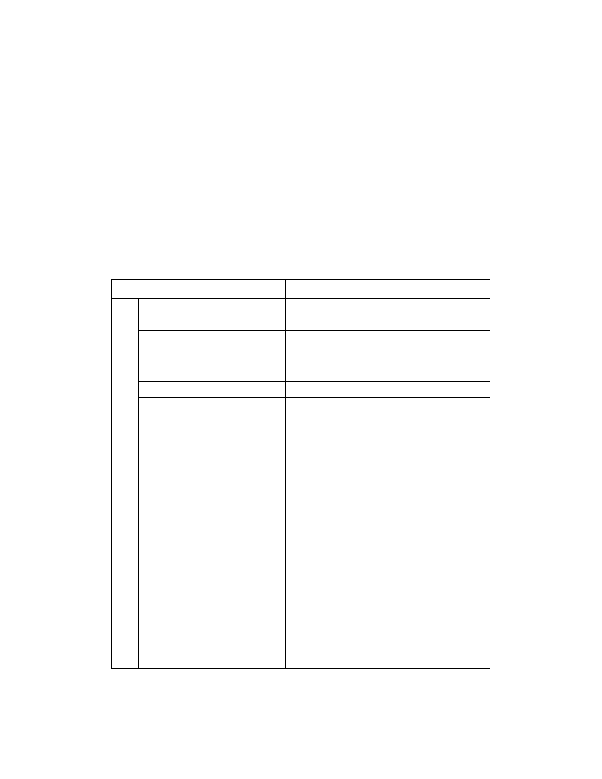
DIP Switch Setting Method
The DIP switches on the CPU are used for start/stop sequence operation
control. The CPU module has six switches as shown in the figure below. The
function of each switch is shown in the following table.
654321
RUN
INIT
TEST
Default
Setting
OFF
NO
ONOFF
FLASH
P.P
COPY
Number Name Setting Operation at Setting
6 RUN ON User Program Run ON
OFF User Program Stop
5 INITIAL ON When SW4 is ON: Clear Memory OFF
OFF When SW4 is ON: Terminal mode
4 TEST ON Terminal Mode/Initialization Mode OFF
OFF Online
3 FLASH ON Program copy from FLASH to RAM OFF
OFF No program copy from FLASH to RAM
2P.P
Default
ON Default Port 1 only OFF
OFF Serial port setting
1 COPY ON M Register Copy when SW3 is ON
Turn the power ON when only SW1 is ON.
SGDH servo parameter in the controller is
transferred to SGDH .
→ to replace
SGDH.
OFF No M Register Copy when SW3 is ON.
M Register has a battery backup.
Although “NO” is displayed on the arrow at the lower right side of the DIP
switches, flipping the switches to the right turns them ON, and left turns them
OFF.
3-3
Page 46

Start, Stop Sequence MotionSuite™ MP940 Machine Controller Reference Manual
Memory Initialization
The memory as initialized, and the user programs and configuration data are
deleted upon setting the DIP switches in the following order, and cycling the
power OFF/ON.
12 3 4 5
Turn MP940
power OFF
Turn DIP
switches INITIAL
and TEST ON.
RUN
56
INITIAL
TEST
FLASH
P.P
1234
COPY
←←←←
NO
Check that the
RDY and RUN
LEDs blink when
power is fed
(approximately
3 seconds).
Return the RUN
DIP switch to the
ON setting
RUN
56
INITIAL
TEST
FLASH
P.P
1234
COPY
←←←←
NO
Turn the power
ON again
Note: The memory is cleared if the battery is removed with the module
power OFF.
Start Sequence
The MP940 makes various determinations at start-up, and upon recognizing
an error, flashes the ERR LED, showing the content of the error by the
number of flashes. MotionWorksTM cannot be operated while the LEDs are
flashing. The following table shows a partial list of the MP940 display LEDs.
3-4
Page 47

MotionSuite™ MP940 Machine Controller Reference Manual Start, Stop Sequence
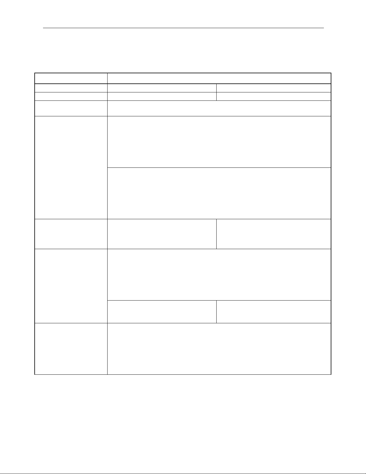
LED
Type
RDY RUN ALM
Normal User program stopped
User program executing normally
Error Hardware reset state (when display continues)
Initializing (when display continues)
Major fault
2 flashes: RAM error
Warning ? ? ? Battery alarm
Operation error (I/O error)
No LED display. Reports to system (S)
register.
Other Memory initialization by DIP switch setting
RDY and RUN flash simultaneously
– Offline testing mode
BAT
ALM
3 flashes: ROM error
4 flashes: Peripheral LSI error
Hardware status (momentary stop, START/
STOP, testing mode, etc.)
complete.
Display Content
:OFF, :ON, :Flash, ?:Undefined
3-5
Page 48

Start, Stop Sequence MotionSuite™ MP940 Machine Controller Reference Manual
MP940 Start Sequence and Basic Operation
Power ON
Test M ode
Switch
Program
Memory
Check
Program
Data
Self-diagnosis
at Start
Run Switch
Determination
Watchdog
Timer Start
Dwg A
Execution
Memory
Clear
= Test Mode
Normal Mode
Not Damaged
Damaged
S Switch Synchronization
Offline Selfdiagnosis
Interrupt Sigma
Dwg 1 Execution
Finished in 1 turn
Dwg S
Scan Processing
Dwg H
Scan Processing
Dwg L
Scan Processing
Online Self-diagnosis
Executed in
descrete time
units
3-6
Page 49

MotionSuite™ MP940 Machine Controller Reference Manual Start, Stop Sequence
The starting sequence and basic operation of the MP940 are as follows:
1. Self-diagnosis at start-up
The following menu is displayed in self-diagnosis at start-up.
• Memory (RAM) Read/Write Determination
• System Program (ROM ) Diagnosis
• Main Processor (CPU) Function Diagnosis
• Numerical Operation Processor (FCPU) Function Diagnosis
The RDY LED flashes the designated number of times when there is an
error in the diagnostic results.
2. Online Self-diagnosis
The following menu is displayed in online self-diagnosis
• System Program (ROM ) Diagnosis
• Main Processor (CPU) Function Diagnosis
• Numerical Operation Processor (FCPU) Function Diagnosis
The RDY LED flashes the designated number of times when there is an
error in the diagnostic results.
3. Start New Run
Sets the run format to New Run in the CP717 system definition screen.
A new run starts. Unlike the start of a continuous run, self-diagnostic
processing occurs prior to DWG.A execution.
4. Operation Stop
The MP940 stops operation in the following situations:
• When power is interrupted
• When power loss occurs
• When a fatal error is generated
• When a STOP operation is executed from MotionWorksTM.
Note: Restart is not possible in the first and second items
above without restarting the power.
Restart is possible in the third item above by turning
off the power.The cause of the error can be deduced by
checking the LED display.
Restart is possible in the fourth item above by executing the RUN operation in CP717.
3-7
Page 50

Scan Processing MotionSuite™ MP940 Machine Controller Reference Manual
Scan Processing
Outline of Scan Processing
There are three types of MP940 scan processing: S (system) scans, H (Highspeed) scans, and L (Low-speed) scans. Scan processing segments all S scan
periods into descrete time elements and then executes the S scan as a base
period.
When setting the proportion of assignments into the background within the S
scan period, ensure the "Background Processing Time" for PP processing.
Scan Types
Type Content
S Scan
(System Scan)
H Scan
(High-speed Scan)
L Scan
(Low-speed Scan)
Select a base period for scan processing: 0.5, 1.0, 2.0, 4.0ms.
S, H and L scan processing segments all S scan periods into discrete time
elements and then executes the S scan as a base period.
Set the S scan period in integer multiples.
The scan is broken into discrete time elements and executed within the S
scan period.
Set the S scan period in integer multiples.
The scan is broken into discrete time elements and executed within the S
scan period.
3-8
Page 51

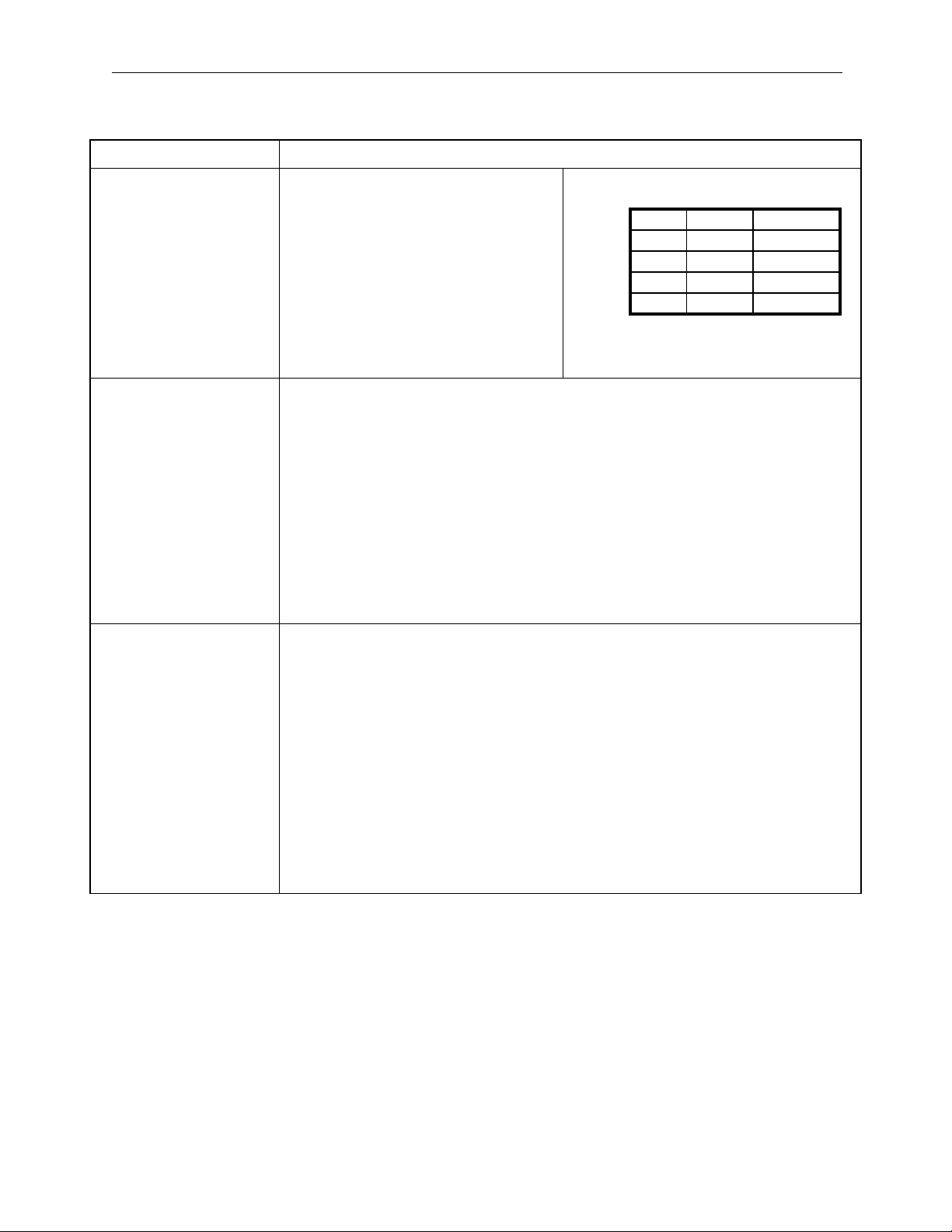
MotionSuite™ MP940 Machine Controller Reference Manual Scan Processing
Service Scan of each Function
Except for SVA, a scan can be selected to execute I/O processing for each
function.
Function
Serviceable
Scans
Notes
CNTR S/H/L Simultaneous processing with S, H, or L
LIO (DI/DO/AI/AO) S/H/L Simultaneous processing with S, H, L
Mechatrolink
H/L Simultaneous processing with either H or L.
(distributed I/O, etc.)
SVA S/H Scan Fixation (unselectable)
Synchronous selection of phase control mode
and position control mode is possible in the
setup parameter settings.
Synchronous Selection of Phase Control
Mode (OBC0016)
0:H Scan (default)/1: S Scan
Synchronous Selection of Position Control
Mode(OBC0017)
0:H Scan/1: S Scan (default)
Content of S Scan
The processing content, as well as procedure, within the S scan is as follows:
S-scan synchronization (set to 0.5, 1.0, 2.0, 4.0ms)
Sスキャン周期(0.5,1.0,2.0,4.0msのいずれか設定)
c
L
n
I
t
O
r
HS SS SA HA LA BG
必須
necessary
(スキャン内で完結)
(completed within the scan)
時限タイマ
limit timer
R
I
O
(1スキャン内で終了しない
(executed in the following
場合次のSスキャンで実行さ
S-scan if not completed
れる)
in 1 scan)
C
O
M
時限付き
time limit
R
I
O
-
余り
loss
background
バックグ
processing
ランド
処理時間
time
3-9
Page 52

Scan Processing MotionSuite™ MP940 Machine Controller Reference Manual
Items Completed within the S Scan
c
L
n
I
t
O
r
HS SS SA
S-scan applications (Dwg. S)
Sスキャンのアプリケーション(DWG.S)
S-scan system processing (no SVA
Sスキャンのシステム処理(SVAの制御ループなど)
control loop)
Hスキャンのシステム処理(SVAの加減速処理など)
4 scan system processing (no SVA accel/
(Hスキャン周期に1回動作します)
decel processing) - operates 1 scan in
ローカルI/O処理(DI/DO/AI/AO)
H scan period
(S/H/Lスキャンのいずれかに同期して処理します。)
マスタエンコーダのカウンタ入力処理(CNTR)
Local I/O processing (DVDO/AI/AO)
(S/H/Lスキャンのいずれかに同期して処理します。
(synchronizes and processes for S/H/L
処理する回のSスキャン割り込みの先頭で処理します。)
scans)
Master encoder counter input processing
(synchronizing processes for S/H/L scans
processed by the head of processing
S-scan interrupt)
Time-shared Items
R
I
HA
O
Background
BG
R
C
I
O
M
LA
O
L-scan application (Dwg. L)
Lスキャンのアプリケーション(DWG.L)
H-scan application (Dwg. H)
Hスキャンのアプリケーション(DWG.H)
Distributed I/O (Mechatrolink) processing
分散I/O(MECHATROLINK)処理
(H/Lスキャンのいずれかに同期して処理します。
(synchronizes & processes the H/L scans)
シリアル通信
Serial communication
Background processing (PP processing)
バックグランドタスク(P.P処理)
3-10
Page 53

MotionSuite™ MP940 Machine Controller Reference Manual Scan Processing
Notes on Scan Processing
1. Complete item processing within the S scan in approximately half the
time of the S scan period setting.
2. Set an assignment ratio in the background processing.
Scan Operation
Each scan process is executed as shown below:
S
スキャン周期
S-scan synchronization
DWG,S
Sスキャン処理
S-scan processing
DWG,H
Hスキャン処理
H-scan processing
DWG,L
Lスキャン処理
L-scan processing
Executed in
タイムスライス
descrete
で実行
time units
Scan Time Setting Method
Opening the Scan Time Setting Window
From the MotionWorks
the Definition Folder.
TM
File Manager, click the Scan Time Setting tab in
3-11
Page 54

Scan Processing MotionSuite™ MP940 Machine Controller Reference Manual
The ScanTime Setting window is displayed.
System Scan Time Setting
The MP940 has three scan time levels (System/High-speed/Low-speed),
which determine the flow of the program execution format. Among these,
the system scan time must be set first. The high-speed/low-speed scans are
then set based upon the system scan.
3-12
Page 55

MotionSuite™ MP940 Machine Controller Reference Manual Scan Processing
The following relationship exists in the setting criteria for the various scan
times. For details, see the MotionSuite™ MP940 Machine Controller
Hardware Manual.
Scan Time Level Setting Criteria
System Scan Select from 0.5, 1, 2, and 4ms.
High-speed scan 0.5 ~ 32ms (system scan integer multiple)
Low-speed Scan 2.0 ~ 100ms (system scan integer multiple)
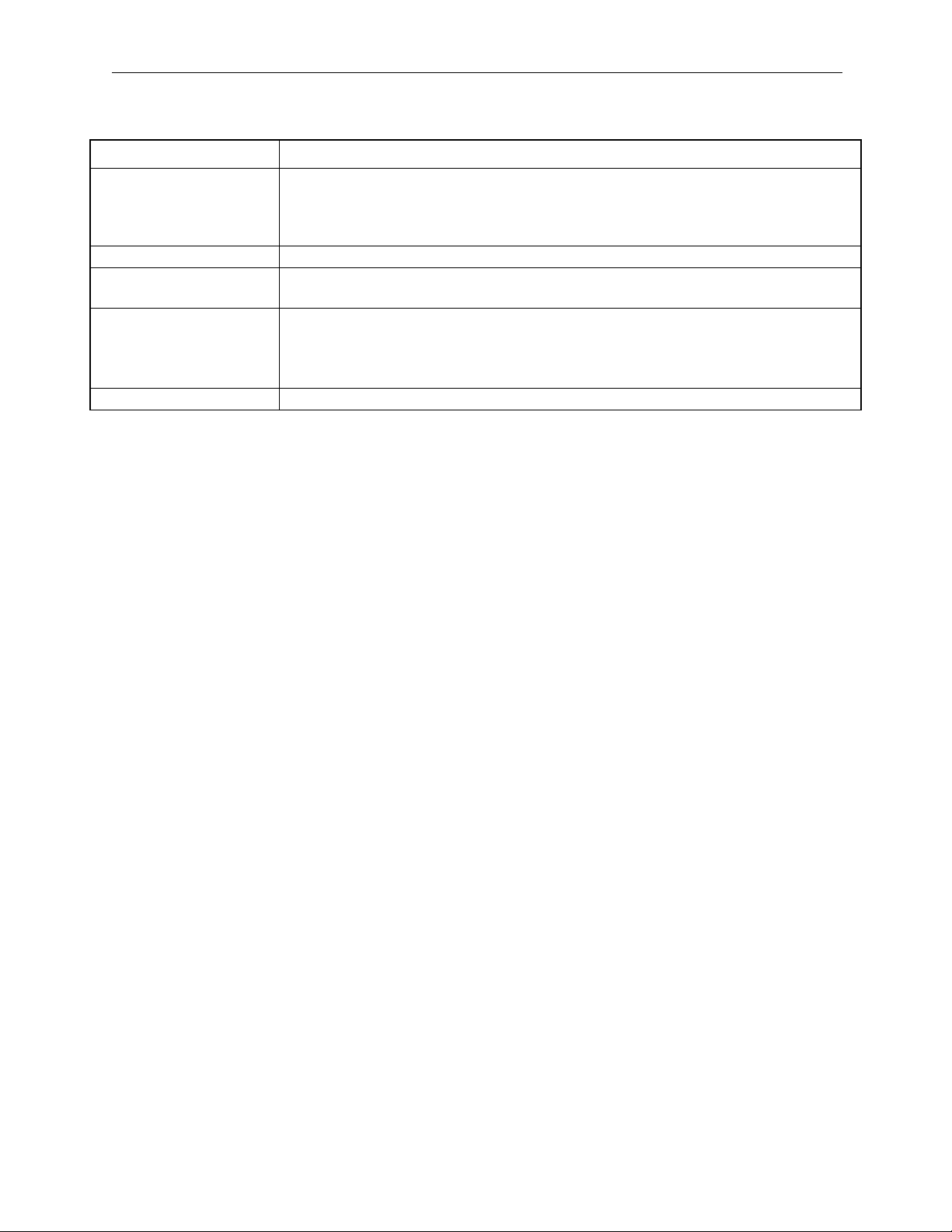
Opening the Setup Window
Select Setup (S), > Base Control Synchronization (B).
Setting Item Content
Set Time Sets the system scan time. The value of the previous step is the current
setting value.
Maximum Time Sets the maximum system scan time. The previous value is the
maximum time measured by the system to this point.
Current Time Displays the current value of the system scan time.
Steps Displays the number of steps of the system scan time.
Background Time Shows the percentage of the total system which is consumed by the
background.
Watch Dog Set Sets the watchdog time which provides system scan time limits.
Restart the power if the base control synchronization has been changed.
The base control synchronization continues to be applied at its current value
and does not return to defaults even if the memory is cleared. Restart power
to return to defaults.
3-13
Page 56

Scan Processing MotionSuite™ MP940 Machine Controller Reference Manual
Scan Time Definition Setting
The machine controller high-speed scan time is displayed in the online mode.
The scan time data stored on the hard drive is displayed in the offline mode.
Setting Item Content
High-speed scan setting Setting: Input the scan setting
Max: Displays the maximum value of the scan. Input “0” here to reset the
maximum scan time value. “0” is displayed in the offline mode.
Current Value: Displays the current value of the scan. “0” is displayed in the
offline mode.
The total number of steps in the scan processing drawing is displayed in
the Number of Steps box.
Low-speed scan setting Sets the low-speed scan time. See the content of the high-speed scan time
box for the meaning of the various data.
Startup DWG steps Displays the total number of steps in the start scan drawing.
Interrupt DWG steps Displays the total number of steps in the interrupt scan drawing.
User function steps Displays the total number of user function steps.
Total steps Displays the total number of steps for all drawings.
Program memory total
(bytes)
Available (bytes) Displays the amount of free space in the program memory. “0” is displayed
Displays the amount of the total program memory (total of drawings, func-
tions, and motion programs) used. “0” is displayed in the offline mode.
in the offline mode.
3-14
Page 57

MotionSuite™ MP940 Machine Controller Reference Manual User Programs
In the online mode, the maximum value may be cleared to "0" by inputting
"0" to the maximum scan time box, and executing the save operation.
Adoption of a new maximum value begins after being cleared.
Saving Scan Time Definitions
The procedure for saving the scan time definitions is shown below.
1. Select File (F) > Save (S).
2. Click the Yes ( Y ) button in the Scan Time message box.
3. Click OK in the message box.
Completion of Scan Time Definition
Complete scan time setting by closing the scan time window. Close the
window by selecting File (F) > Close (C) from the menu.
User Programs
This section describes user program types, priority, processing formats, etc. for basic
operation of the MP940.
DWG (drawing)
User programs are controlled in drawing units classified by drawing number
(DWG number). These drawings form the basis of the user program.
Drawings consist of source drawings, sub-drawings, and sub-sub-drawings.
Drawings can be either functions which seperately and freely reference
individual drawings, or motion programs which reference an H drawing only.
• Source Drawing
This is automatically executed by the system program at establishment of the
execution conditions in the following table.
• Sub-drawing
These are executed by reference from a source drawing using the SEE command.
3-15
Page 58

User Programs MotionSuite™ MP940 Machine Controller Reference Manual
• Sub-sub-drawing
These are executed by reference from a sub-drawing using the SEE command.
• Operation Error Processing Drawing
These are automatically executed by the system program at operation error
generation.
• Functions
These are executed by referencing a source drawing, sub-drawing, or subsub-drawing using an FSTART command.
• Motion Programs
These can only reference H drawings. They are executed by referencing a
source drawing, sub-drawing, or sub-sub-drawing using an MSEE command.
Types and Priority of Source Drawings
Source drawings are classified by their first letters (A, I, S, H, L) in
accordance with their processing objective. Priority and execution
conditions are determined as follows.
Types and Priority of Source Drawings
Type of
Source
Drawing
DWG.A Start Processing 1 Power Feed (executed once at
DWG.I Interrupt Processing 2 Generated by DI interrupt and
DWG.S System Scan 3 Set Interval Start (executed at each
DWG.H High-speed Scan
DWG.L Low-speed Scan
Drawing Role Priority Execution Conditions
power ON)
counter coincidence interrupt for
option modules executed by
external interrupt
servo control scan time)
4 Divides the servo control scan (S
Processing
Processing
scan) period into discrete time elements to execute the scan.
5 Divides the servo control scan (S
scan) period into discrete time elements to execute the scan.
Number of
Drawings
(Note)
4
8
16
16
32
3-16
Page 59

MotionSuite™ MP940 Machine Controller Reference Manual User Programs
An annotated description of the number of drawings for each type of drawing
is given below.
Drawing Number of Drawings
DWG.A DWG.I DWG.S DWG.H DWG.L
Source Drawing
Operation Error Processing Drawing
Sub-drawing
Sub-sub-drawings
1 (A) 1 (I) 1 (S) 1(H) 1 (L)
1 (A00) 1 (I00) 1 (S00) 1 (H00) 1 (L00)
Maximum of 2
drawings
combined
Maximum of 6
drawings
combined
Maximum of
14 drawings
combined
Maximum of
14 drawings
combined
Maximum of
30 drawings
combined
Source Drawing Execution Control
Source Drawing Execution Control
Each drawing is displayed as shown below based on its priority.
Power ON
電源投入
電源投入
Power ON
DWG,A
DWG,A
Start processing
Start processing
始動処理図面
始動処理図面
drawing
drawing
S-scan synchronization
S
スキャン周期
S
スキャン周期
DWG,S
DWG,S
Sスキャン処理
Sスキャン処理
S-scan processing
S-scan processing
S-scan processing
DWG,H
DWG,H
Hスキャン処理
Hスキャン処理
H-scan processing
DWG,L
DWG,L
Lスキャン処理
Lスキャン処理
L-scan processing
演算エラー
演算エラー
Operation error
DWG,X00
DWG,X00
Operation error
演算エラー処理図面
演算エラー処理図面
processing drawing
X,A,I,S,H,L
X,A,I,S,H,L
もとの続き
もとの続き
Continuation
Executed in
タイムスライス
タイムスライス
discrete time
で実行
で実行
units
割り込み信号
割り込み信号
Interrupt signal
DWG,I
DWG,I
Interrupt processing
割り込み処理図面
割り込み処理図面
drawing
もとの続き
もとの続き
Continuation
3-17
Page 60

User Programs MotionSuite™ MP940 Machine Controller Reference Manual
Layer Structure of Drawings
Each drawing comprises source, sub-, and sub-sub-drawings. It is not
possible to reference sub-drawings of a different type from the source
drawing, nor is it possible to reference sub-sub-drawings of a different type
from the sub-drawing. It is also impossible to reference sub-sub-drawings
directly from source drawings. A structure wherein sub-drawings are
referenced from source drawings, and sub-sub-drawings from sub-drawings
is neccessary. This is called the layer structure of the drawing.
Drawing Execution
Create user programs as shown below by layering processing programs into
source drawings, sub-drawings, and sub-sub-drawings.
親図面 子図面 孫図面
Source drawing Sub-drawing
DWG.X DWG.X01.01
Note: “x” substitutes for A, I, H, and L.
(注) Xは,A,I,H,Lに置き換えてください。
DWG.X01
DWG.Xnn
Sub-subdrawing
DWG.X01.02
DWG.X01.03
Note: The system automatically executes the source drawing
since the execution conditions for each function have
been decided according to Table XXX. This means
that source drawings are automatically called by the
system.It is therefore possible for the customer to execute various sub-drawings and sub-sub-drawings by
programming drawing reference commands (SEE
commands) in the source and sub-drawings.
・
・
モーションプログラム
Motion Program User Functions
MPM001
・
・
・
ユーザ関数
FUNC-001
・
・
MPM002
・
・
・
MPM015
FUNC-006
・
・
FUNC-032
・
・
FUNC-064
Functions can be referenced from any drawing.Functions can also be referenced from any function.
An operation error drawing starts, corresponding to a
given drawing when an operation error occurs within
that drawing.
3-18
Page 61

MotionSuite™ MP940 Machine Controller Reference Manual User Programs
Reference motion programs from the H drawing with
an MSEE command. Source drawings, sub-drawings,
or sub-sub-drawings can be referenced in an H drawing.
Source drawings are automatically called by the system. Sub-drawings are referenced from a source drawing using the SEE command. Therefore, user programs
cannot be executed using only sub-drawings and subsub-drawings.
Drawing Execution Processing Format
The execution processing of each layered drawing is processed in a format
which references from the upper-level drawings to the lower-level
drawings.The DWG (drawing) layer structure is shown in the following
diagram using DWG.A as an example.
System Program
システムプログラムが
start and execution conditions
実行条件で起動
親図面 子図面 孫図面
Source Drawing Sub-drawing Sub-sub-drawing
DEND
DWG.A
SEE A01
SEE A02
DWG
DWG.A01
SEE A01.01
SEE A01.02
DEND
DWG.A02
演算エラー
Operation
error
note:
記述:
DWG.X YY . ZZ
発生
システムが
system starts
自動的に起動
automatically
DWG.A01.01
FUNC-001
DEND
DWG.A01.02
FUNC-001
DEND
DWG.A00
DENDDEND
孫図面番号
Sub-sub-drawing number (01 ~ 99)
子図面番号
Sub-drawing number (01 ~ 99)
親図面の種類
Source drawing tType A, I, S, H, L
~
99)
(01
~
99)
(01
(A, I,S, H, L)
Function
FUNC-001
DEND
関数
:DWG. X 00
3-19
Operation error drawing
演算エラー図面
(A, I, S,H, L)
Page 62

User Programs MotionSuite™ MP940 Machine Controller Reference Manual
Motion Programs
Outline of Motion Programs
1. A motion program is a program written in a text format motion language. Unlike ladder programs, up to 256 motion programs can be created.
2. There are two types of motion programs: main programs that can be
called from DWG.H (MPMooo), and sub-programs that can be called
from the main program (MPSooo).
Classification
Designation
Method
Main Program MPMooo
1 ~ 32
Sub-program MPSooo
1 ~ 32
Ensure that the program numbers for MPMooo and MPSooo are different.
3. There are two methods of motion program designation, direct designation (in which the program number is designated), and indirect designation (in which a register number containing the program number is
stored is designated). Examples of direct designation and indirect designation (respectively) appear below.
Characteristics No. of Programs
Can be called from DWG.H A combined maximum of
main and sub-programs,
Can be called from main program
ABS;
up to 32, can be created
MC
プログラム起動命令
Program start command
MSEE MPM001 DA0000
↑
MPM Number
MPM
番号
Ladder Program MC Program
ラダープログラム
MOV
MVS
IOW MB0001
MOV
[X]
[X]
[X]
MC
プログラム
_
_ F
_
・
・
3-20
Page 63

MotionSuite™ MP940 Machine Controller Reference Manual User Programs
ABS;
MOV
MVS
IOW MB0001
0 3
Setting Device
設定器
MC
プログラム起動命令
MC program start command
MSEE MW00200 DA0000
MOV
MPM
MW00200
番号
MPM signal
Ladder Program MC Program
ラダープログラム
Motion Program Execution Processing Formats
Reference motion programs from the H drawing with an MSEE command.
Source drawings, sub-drawings, or sub-sub-drawings can be referenced in an
H drawing.
Start of system program
システムプログラムが
with operating conditions
実行条件で起動
Source drawing Sub-drawing Sub-sub-drawing Motion Program
親図面
DWG.H
SEE
H01
子図面
DWG.H01
SEE H01.01
MSEE
MSEE
MPM002
MPM002
孫図面
DWG.H01.01
MSEE
MPM001
DEND
(more)
(注)
(more)
(注)
モーションプログラム
MPM00
1
VEL [a1]5000
FMX T10000000;
IAC T25;
IDC T30;
MOV [a1]300.
MVS [a1]200.
.
.
.
.
END
MPM00
2
[X]
[X]
[X]
MC
プログラム
_
_ F
_
・
・
DEND
MSEE
MPM002
DEND
3-21
END
END
MPM00
3
MSEE
MPS001
サブルーチン
Sub-routine
MPS00
1
RET
Page 64

User Programs MotionSuite™ MP940 Machine Controller Reference Manual
1. The ladder commands of the H drawing are executed at each highspeed scan period in the order of source drawing/sub-drawing/sub-subdrawing.
2. Although motion programs are referenced in the scan period, they cannot be referenced in a single scan. Motion programs execute an execution control dedicated to motion programs through the motion control
functions of the system.
3. Although motion programs are referenced in the scan period, they cannot be executed simply by reference. A control signal set in the group
definition screen must be set.
Ensure the following restrictions are observed in referencing motion
programs.
1. Multiple reference of motion programs with the same number is not
possible with the MSEE command.
2. Subroutines (MPSxxx) cannot be referenced from ladder MSEE commands. These can only be referenced from within the motion program
(MPMxxx, MPSxxx).
3. The same subroutine cannot be simultaneously referenced.
Motion Program Execution
Input program control signals (program run start requests, program stop
requests, etc.) in order to execute the motion programs called from DWG.H
by the MSEE command. Operation is possible by inputting the external
control signal defined in the group definition screen into the program control
signal.
1. The following signal types are for motion program control.
bit Signal Name Signal Type
b0: Program Run Start Request Bit Input
b1: Program Hold Request A Contact
b2: Program Stop Request A Contact
b3: Program Debug Mode Selection A Contact
b4: Program Debug Start Request Bit Input
b5: Alarm Reset Request A Contact
b8: Skip 1 Data A Contact
b9: Skip 2 Data A Contact
3-22
Page 65

MotionSuite™ MP940 Machine Controller Reference Manual User Programs
2. Control of motion program run/stop/hold, etc., is possible by inputting
these signals in a ladder program into a work register +1 designated by
the MSEE command. Convert the ladder program input to a signal in
accordance with the signal types in step 1, above.
The program restarts after program close if the start signal is input to
the A contact.The program does not operate with the start signal on an
ON state at power ON.
3. The motion program execution processing method is shown below.
Motion Control Functions
External Control Signal
Run Status
Hold
Stop etc.
DWG.H
Motion
Program
Control Ladder
MSEE MPM001
DA00000
Motion
Program
Number
DEND
Program RUN Status
Program HOLD
Program STOP etc.
Program
Control
Signal
MSEE
Work
Register
Address
MSEE Work Register
Status
Control Signal
MPM001
VEL [a1]5000
FMX T10000000;
IAC T25;
IDC T30;
MOV [a1]300.
MVS [a1]200.
.
.
.
.
END
Ladder Program Motion Program
3-23
Page 66

User Programs MotionSuite™ MP940 Machine Controller Reference Manual
Motion Program Status Flags
The first word of the MSEE work register is a motion program status flag
which tells the user the execution status of the motion program. The detailed
contents of the status flag are shown below.
bit Status
b0: Program Running
b1: Program Hold
b2: (used by system)
b3: (used by system)
b4: Program Debug Running
b8: Program Alarm Generated
bB: In Debug Mode (EWS debug run)
bE: Main Program Duplication Error
bF: Excessive Main Program Number Error
Example of Motion Program Control Ladder
1. The minimum necessary ladder program to control a motion program is
shown below.
3-24
Page 67

MotionSuite™ MP940 Machine Controller Reference Manual User Programs
2. The content of the above ladder program is as follows:
Step
Number
1 ~ 7 Stores the signal connected to the external input signal of the MP940 into the
motion program control signal.
IW0000 (External Input Signal) ¨_ DW00001 (27th word of MSEE work register)
Program Run Start
Program Hold
Program Stop
Alarm Reset
9 Call-out of motion program MPM001
MSEE MPM001 DA00000
(1) (2)
(1) Motion Program Number
(2) MSEE Work Register Address
11 ~ 15 Reset the run mode setting alarm reset (B6 of OWxx00) for each axis setting
parameter and clear the alarms on each axis by the alarm reset signal (IB00005).
Program Content
3. Motion program run/hold/stop, etc., operation by the system motion
control function is possible when the external I/O signals (IB00000 ~
IB00007) connected in the MP940 by the above ladder program are
input as motion program control signals (word 27 of the MSEE work
register).
The following table provides an example of the external input signals
required to create the minimum neccessary in order to operate a motion
program in the MP940.
External
Signal
Address
IB00000: Program Run Start B0: Program Run Start Request
IB00001: Program Hold b1: Program Hold Request
IB00002: Program Stop b2: Program Stop Request
IB00003: Program Debug Mode b3: Program Debug Mode Selection
IB00004: Program Debug Start b4: Program Debug Start Request
IB00005: Alarm Reset b5: Alarm Reset Request
External Signal Name BIT
Motion Programs
Control Signal
Motion Control Ladder Autotmatic Generation Function
An automatic generation function for motion control ladders is standard
equipment in the MP940. Using this function, both jog operations and
programmed runs may be performed without having to create a dedicated
ladder program. Additionally, the system boot-up time is greatly reduced.
3-25
Page 68

User Programs MotionSuite™ MP940 Machine Controller Reference Manual
Number of motion programs that can
be simultaneously started in the H drawing
Input
signal
by group
Automatic generation of motion
control ladder program
Input
signals
by axis
The motion control ladders are automatically generated according to external
input signals assigned in the group definition screen. They can be used as;
however, use of this ladder as a template is recommended (but only after
optimization/modification to match the system).
3-26
Page 69

MotionSuite™ MP940 Machine Controller Reference Manual Functions
Functions
This section describes the usage method, characteristics, etc. of the MP940 functions.
Functions are executed by referencing a source drawing, sub-drawing, or sub-subdrawing using an FSTART command. Unlike sub-drawings and sub-sub-drawings,
function references can be freely executed from the various drawings. The same function can also be referenced simultaneously from different drawing types and layers.
Functions created from other functions can also be referenced. The following advantages are derived from using functions.
• Program componentization can be easily achieved.
• Program creation/saving is easy.
There are two types of functions: standard system functions provided with the system, and user functions defined by the user.
Standard System Functions
Nine functions are installed as standard system functions.The user cannot
modify the standard system functions, listed below.
Type Name Symbol Content
System
Functions
Counter COUNTER Up/Down Counter
First-in/First-out FINFOUT First-in/First-out
Trace Function TRACE Data Trace Execution Control
Data Trace Read-out DTRC-RD Data read from data trace memory into the
user memory.
Message Sent MSG-SND Send message from controller.
Message Receive MSG-RCV Receive message to controller.
User Functions
The function itself (program) can be freely defined (programed) by the user.
Up to 32 user program definitions can be created. The technique for creating
user programsby using the user function creation procedure is described
below.
3-27
Page 70

Functions MotionSuite™ MP940 Machine Controller Reference Manual
Determination of I/O
Specifications
Function Definition Creation
Function Program Creation
Function Reference
Program Creation
Determine the number of I/Os and data types.
Input using CP-717
Created in the same manner as a drawing. However the
registers used differ. Pay attention to the correspondence of
the I/O data at function reference with the register numbers
used in the function program.
Input in the following order:
(1) Input the function name with the FSTART command
(2) Connect the input data using the FIN command.
(3) Connect the output data using the FOUT command.
1. See the following manual for details on MotionWorksTM operating
methods. MP9xx Programming Unit Software Manual (volumes 1 and
2) (SIZA-C887-2.2-1/2.2-2).
2. See the following manual for details on the FSTART command and
other commands.
MP9xx Programming Manual (SI-C887-1.2C)
3-28
Page 71

MotionSuite™ MP940 Machine Controller Reference Manual Functions
Determination of I/O Specifications
When creating a user funtion, determine the number of I/Os needed to meet
the specifications required, as detailed in the table below.
User Determined Specifications Outline
Function Name Input a name of up to 8 characters.
Number of Inputs Up to 16 input indices for the functions can be input.
Up to 17 can be input along with the number of address inputs.
Number of Address Inputs* Up to 1 of these can be input in the exponent of the addresses
needed in the function.
Number of Outputs Up to 16 outputs from a function can be input.
• This shows how many pointers have been provided to the external function
register used in the function.
Creation of External Function Definitions
1. Defines the specifications determined in the “Determination of I/O
Specifications” section, such as function name in MotionWorksTM. For
details on the operation method, see MP9xx Programming Unit Software Manual (vol. 1 and 2) (SIZ-C887-2.2-1/2.2-2).
Example: Graphical Function Display Format defined as Func-
tion Name = “TEST”, No. of Inputs = “4”, No. of
Address Inputs = “1”, No. of Outputs = “4”.
TEST
IN_01
IN_02
IN_03
OUT_01
OUT_02
OUT_03
IN_04
OUT_04
IN_05
3-29
Page 72

Functions MotionSuite™ MP940 Machine Controller Reference Manual
Note: After the graphical display format of the function has
been created, define the data types of the function
inputs, outputs, and address inputs.
There are three types of definable data types: bit, integer, and double-length integer.
Upon defining the data types, these are automatically
assigned according to the system where input = X register, output = Y register, address input = A register.
2. An example of the function input definitions is given below:
TEST
Bit-type
Numerical Input
Bit-type
Numerical Input
Real Number
Numerical Input
Integer
Numerical Input
===>
===>
IN_01
BIT1
IN_02
BIT2
IN-03
FLT1
IN-04
INT1 INT2
IN_05
ADR
OUT_01
OUT_02
OUT_03
OUT_04
BIT3
BIT4
LNG1
Bit-type
Numerical Output
Bit-type
Numerical Output
Double-length
Integer Numerical
===>
Integer
Numerical Output
===>
3. The I/O signal addresses are automatically assigned from the signals on
the graphical expression. Each of the I/O address assignments in the
example above are as follows:
Name Data Type I/O Register
IN_01 (BIT1) Bit type XB000000
IN_02 (BIT2) Bit type XB000001
IN_03 (FLT1) Real number type XF00001
IN_04 (INT1) Integer type XW00003
IN_05 (ADR) Address input type AW00000
OUT_01 (BIT3) Bit type YB000000
OUT_02 (BIT4) Bit type YB000001
OUT_03 (LNG1) Double-length integer type YL00001
OUT_04 (INT2) Integer type YW00003
Output
• XW00000 and YW00000 of the X and Y registers are used as bit type data.
3-30
Page 73

MotionSuite™ MP940 Machine Controller Reference Manual Functions
4. The function input register is automatically assigned for “Graphical
Function Display Format 2”. The general structure of the function is
created at this stage.
Creation of the Function Program
The creation method is the same as for a drawing. However, the register type
used differs. For details on the registers, see the Register Types section.
Creation of the Function Reference Program
The user function is complete upon creation of the graphical function display
format and program. Referencing is possible, just as in standard system
functions, from source drawings, sub-drawings, and sub-sub-drawings, in
addition to other functions. Functions may be called-out within both drawing
and user function programs by the following procedure. For details on the
operation method, see “MP9xx Ladder Programming Manual” (SI-C887-
1.2C).
1. Input the function name with the FSTART command.
For example, input FSTART, press the Enter key, input TEST, and
press the Enter key. Already defined graphical function display formats are then displayed.
2. Use the FIN command to create the input data program. This imparts
the input data to both the function inputs and address inputs.
3-31
Page 74

Functions MotionSuite™ MP940 Machine Controller Reference Manual
3. Use the FOUT command to create the output data program. For example, the I/O data is imparted as follows to graphical display format.
TEST
DB000000
DB000001
DF00001
DW00003
DB000020
= = = >
= = = >
BIT1
BIT2
FLT1
FLT2 INT2
ADR
MA00300
BIT3
BIT4
LNG1
= = = = >
====>
DB000021
DL00010
DW00012
The relationship between I/O data and the internal function registers is
listed below.
Name I/O Data
Internal Function
Register
BIT1 DB000000 XB000000
BIT2 DB000001 XB000001
FLT1 DF00001 XF00001
INT1 DW00003 XW00003
ADR MA00300 AW00000
BIT3 OB00020 YB000000
BIT4 OB00021 YB000001
LNG1 DL00010 YL00001
INT2 DW0012 YW00003
3-32
Page 75

MotionSuite™ MP940 Machine Controller Reference Manual Functions
The address input register AW00000 in the above table is assigned to
MW00300. AW00000, AW00001... used within the function test, cor-
respond to the external registers MW00300, MW00301.... Therefore,
if a value in AW00000 is stored in a function, that value is stored in
MW00300, as shown below.
Internal
Function
AW00000
AW00001
AW00002
AW00003
Pointer
External
Register
MW00300
MW00301
MW00302
MW00303
MA00300
Creation of function reference programs from motion programs
User functions can be called out from motion programs. For example, the
following results when the user function on the previous page is called out
from the motion program.
UFC TEST DB000000 DB000001 DF00001 DW00003,MA00300,
DB000020 DB000021 DL00010 DW00012;
User program conditions referenced in motion programs
The first bit of the I/O data is always in bit form. This output data is assumed
to be the “completion” signal for shifting the following motion commands.
UFC DB000000..., MA00300, DB000020...; Conditions@_DB000020==ON
MVS [X]100. [Y]200. F10000;
•
••
3-33
Page 76

Register MotionSuite™ MP940 Machine Controller Reference Manual
Register
This section describes register types and usage formats used in MP940 user programs.
Register Designation Method
There are two methods for register designation: direct designation of register
numbers, and symbol designation. These methods may be used together in a
user program. When symbol deignation is used, the relationship between
symbols and register numbers is defined in the symbol table given later. The
register designation method is shown below.
Designation Method Designation Method
Direct Register
Number Designation
Symbol Designation Bit type Register Designation: RESET1-A.X
Bit type Register Designation: MB00100AX
Integer Type Register Designation: MW00100X
Double-length Integer Type Register Designation: ML00100X
Real Number Type Register Designation: MF00100X
Address Type Register Designation: MA00100X
X: In suffix designation, attach a suffix or a J after the register number.
Integer Type Register Designation: STIME-H.X
Double-length Integer Type Register Designation: POS-REF.X
Real Number Type Register Designation: IN-DEF.X
Address Type Register Designation: PID-DATA
Up to 8 alphanumeric characters
X: In suffix designation, attach a period “.” after the symbol up to 8
alphanumeric characters, then add a suffix or a J.
Register Number Direct Designation
.X
Register#:V T No.(Bit No.) (suffix)
T=B (bit type) when (Hex: 0~F)
Register number communicated by V (DEC/
HEX)
Data type communicated in V (T:B|W|L|F|A)
Register Types
DWG (V:S|M|I|O|C|#|D)
Function (V:S|M|I|O|C|#|D|X|Y|Z|A)
3-34
i or j can be designated
as suffixes
Page 77

MotionSuite™ MP940 Machine Controller Reference Manual Register
Symbol Designation
Type
Symbol: (Symbol Name) (.) (Suffix)
Needed when using a suffix (symbol
name and suffix classification)
Register name up to 8 characters
X X X X X X X X
Data Types
There are five data types used according to purpose: bit, integer, double-byte
integer, real number, and address. Address type data is only used for bottom
designation within a function. For details, see MP9xx Ladder Programming
Manual (SI-C887-1.2C). The data types are shown below.
Data
Type
Numerical Range Notes
i or j can be designated
as a suffix
English Alphanumerics/Symbols
Roman Letters or symbols (a number cannot
be designated at the head of a symbol name)
B Bit ON, OFF Used in relay circuits.
W Integer -32768 ~ +32767
(8000H) (7FFFH)
Used in numerical calculations. Data
in parentheses “( )” indicates use in
logical calculations.
L Double-
length
integers
F Real
-2147483648 ~ +2147483647
(80000000H) (7FFFFFFFH)
Used in numerical calculations. Data
in parentheses “( )” indicates use in
logical calculations.
±(1.175E -38 ~ 3.402E +38), 0 Used in numerical calculations.
numbers
A Address 0 ~ 32767 Used only in pointer designations.
3-35
Page 78

Register MotionSuite™ MP940 Machine Controller Reference Manual
Register Designation and Data Type
FEDCBA9876543210
[ MW00100 ]
[ MW00101 ]
[ MW00102 ]
[ MW00103]
Pointer Designation
Memory
Addresses
nn
[ MA00100 ]
Register Area
・
・
・
[ MB00103A ]
[ MB001003 ]
[ MW00100 ]
[ MW00101 ]
[ MW00102 ]
[ MW00103 ]
[ MB001006 ]
[ ML00100 ]
[ MF00100 ]
[ ML00102 ]
[ MF00102 ]
[ ML00100 ]
[ MF00100 ]
3-36
Page 79

MotionSuite™ MP940 Machine Controller Reference Manual Register
Usage examples by data type
1. Bit
Used in relay circuit ON/OFF or logical calculation.
IB000100
IB000001
IFON
OB000001
V
1
• Sample motion program
MB000101=IB000100;
IF IB000001==1;
DB000001=DB000001|1
2. Word
Used in numerical calculations and logical calculations.
MB000101
OB000001
MW00100 V
MW00102 +
MW00104
H00FF
12345
INV
• Sample motion program
MW00101=MW00100|00FFH;
MW00103=MW00102+12345;
MW00105=MW00104;
MW00101
MW00103
MW00105
3-37
Page 80

Register MotionSuite™ MP940 Machine Controller Reference Manual
3. Double-length Integers
Used in numerical calculations and logical calculations.
ML00100
ML00106
ML00112
+
ML00102
×
ML00108 ÷÷18000
BIN
• Sample motion program
ML00104=ML00100+ML00102;
ML00110=ML00106∗ML00108/18000;
ML00114=BIN (ML00112);
4. Real Numbers
Used in numerical calculations with floating points.
1.23456
DF00102 SIN
(30.0) (0.5)
DF00200 TAN
(45.0) (1.0)
ML00104
ML00110
ML00114
DF00100
(1.23456)
DF00104
DF00202
• Sample motion program
DF00100=1.23456;
DF00104=SIN (DF00102);
DF00202=TAN (DF00200);
3-38
Page 81

MotionSuite™ MP940 Machine Controller Reference Manual Register
5. Address
Used only in pointer designation.
MF00200~MF00228 are used as a parameter table.
MF00200
PID MA00200
Parameter Table
Head Address
MF00200~MF00204 are used as a parameter table.
MW00200
LAG MA00200
Parameter Table
Head Address
Deviation Input
Input
⇒
MF00022
PID Output
⇒
MW00022
LAG
Output
3-39
Page 82

Register MotionSuite™ MP940 Machine Controller Reference Manual
Register Types
DWG Register
Each drawing or motion program can use the seven registers shown below.
Type Name
SSystem
Register
M Data Reg-
ister
I Input
Register
OOutput
Register
C Constant
Register
# # Register #B, #W, #L,
D D Register DB, DW, DL,
Designation
Method
SB, SW, SL,
SFnnnnn
(SAnnnnn)
MB, MW, ML
, MFnnnnn
(MAnnnnn)
IB, IW, IL, IFhhhh
(IAhhhh)
OB, OW, OL,
OFhhhh
(OAhhhh)
CB, CW, CL,
CFnnnnn
(CAnnnnn)
#Fnnnnn
(Annnnn)
DFnnnnn
(DAnnnnn)
Range Content Characteristics
SW00000 ~
SW01023
MW00000 ~
MW32767
IW0000 ~
IW07FF
OW0000OW
07FF ~
OW07FF
CW00000 ~
CW32767
#W00000 ~
#W16383
DW00000 ~
DW16383
Register prepared by the system. Register number nnnnn
is displayed in decimal format.
SW00000 ~ SW00049 are
cleared to 0 at system start.
Common registers between
each drawing. Used in I/Fs
between drawings, register
number nnnnn is displayed in
decimal format.
Register used in input data.
Register number nnnnn is displayed in hexadecimal format.
Register used in output data.
Register number hhhh is displayed in hexadecimal format.
This register can only be referenced in programs. Register number nnnnn is displayed
in decimal format.
This register can only be referenced in programs. Only
given drawings can be registered. The actual usage range
is designated by the user in
MotionWorks
number nnnnn is displayed in
decimal format.
This is an internal register
intrinsic to each drawing. Only
given drawings can be registered. The actual usage range
is designated by the user in
the MotionWorks
number nnnnn is displayed in
decimal format.
TM
. The register
TM
. Register
Common DWG
By Drawing
3-40
Page 83

MotionSuite™ MP940 Machine Controller Reference Manual Register
1. # registers cannot be used in motion programs.
2. The following registers are saved in flash memory.
• M Registers
• C Registers
• # Registers (saved with user programs)
• D Registers (saved with user programs)
3-41
Page 84

Register MotionSuite™ MP940 Machine Controller Reference Manual
Function Registers
The 11 types of registers shown below can be used in each function.
Function Registers
Type Name
X Function
Input
Register
Y Function
Output
Register
Z Internal
Function
Register
AExternal
Function
Register
# # Register #B, #W, #L,
D D Register DB, DW, DL,
Designation
Method
XB, XW, XL,
XFnnnnn
YB, YW, YL,
YFnnnnn
ZB, ZW, ZL,
ZFnnnnn
AB, AW, AL,
AFhhhh
#Fnnnnn
(Annnnn)
DFnnnnn
(DAnnnnn)
Range Content Characteristics
XW00000 ~
XW00016
YW00000 ~
YW00016
ZW0000 ~
ZW00063
AW0000 ~
AW32767
#W00000 ~
#W16383
DW00000 ~
DW16383
Input to Function
Bit Input: XB000000 ~ XB00000F
Integer Input: XW00001 ~ XW00016
Double-length Integer Input: XL00001 ~
XL00015
Register number nnnnn is displayed in
decimal format.
Output from function
Bit Output: YB000000 ~ YB00000F
Integer Output: YW00001 ~ YW00016
Double-length Integer Output: YL00001
~ YL00015
Register number nnnnn is displayed in
decimal format.
This is an internal register intrinsic to
each function. These can be used as
internal function processes. Register
number nnnnn is displayed in decimal format.
This external address assumes the value
of the address input to be the base
address.
For linking with (S, M, I, O, #, DAnnnnn).
Register number nnnnn is displayed in
decimal format.
This register can only be referenced in
functions. Only given functions can be
registered. The actual usage range is
designated by the user in
MotionWorks
is displayed in decimal format.
This is an internal register intrinsic to
each function. Only given functions can
be registered. The actual usage range is
designated by the user in
MotionWorks
is displayed in decimal format.
TM
. Register number nnnnn
TM
. Register number nnnnn
By Function
3-42
Page 85

MotionSuite™ MP940 Machine Controller Reference Manual Register
Function Registers (Continued)
Type Name
S System
Register
M Data
Register
I Input
Register
O Output
Register
C Definition
Register
Designation
Method
SB, SW, SL,
SFnnnnn
(SAnnnnn)
MB, MW, ML,
MFnnnnn
(MAnnnnn)
IB, IW, IL, IFhhhh
(IAhhhh)
OB, OW, OL,
OFhhhh
(OAhhhh)
CB, CW, CL,
CFhhhh
(CAhhhh)
Range Content Characteristics
Same as DWG register
Because this register is common to drawings and functions, use this register carefully when referencing identical
functions from drawings of different priority levels.
SA, MA, IA, OA, DA, A, and CA can be used within functions as well.
Usage Method for Suffixes I and J
By function
Two types of dedicated register, I and J, have been provided for modification
of relay numbers and register numbers. The functions of I and J are exactly
the same. Examples of each register data type follow below.
If the suffix is in bit form
The value of I is the same as the value of J when added to a relay number.
For example, when I = 2 MB000000l is the same as MB000002. When J = 27
MB000000J is the same as MB00001B.
2I
MB000000i
Equal
MB0000002
If the suffix is in integer form
The value of I is the same as the value of J when added to a register number.
For example, when I = 3 MW000010l is the same as MW00013. When J = 30
MW00001J is the same as MW00031.
3-43
Page 86

Register MotionSuite™ MP940 Machine Controller Reference Manual
00030
MW00001j
J
Equal
MW00031
If the suffix is in double-length integer form
The value of I is the same as the value of J when added to a register number.
For example, when I = 1 ML00000l is the same as ML0000I. Be aware that
ML0000J is as follows when J = 0 and when J = 1.
When J=0 ML00000J: ML00000
When J=1 ML00000J
:
ML00001
Upper-level
Word
MW00001
MW00002
Lower-level
Word
MW00000
MW00001
If the suffix is in real number form
The value of I is the same as the value of J when added to a register number.
For example, when I = 1 MF00000l is the same as MF0000I. Be aware that
MF0000J is as follows when J = 0 and when J = 1.
When J=0 MF00000J: MF00000
When J=1
MF00000J
:
MF00001
Upper-level
Word
MW00001
MW00002
Lower-level
Word
MW00000
MW00001
Example of Program Using Suffixes
Using suffix J, this program requests a total of 100 registers from MW00100
to MW0199 into MW00200.
00000
FOR J = 00000 to 00099 by 00001
MW00200 + MW00100j
FEND
MW00200
MW00200
3-44
Page 87

MotionSuite™ MP940 Machine Controller Reference Manual Register
Suffixes I and J cannot be used in motion programs.
• I and J require initialization.
• I and J are handled in unsigned form. Do not allow their values to drop below zero.
Function I/O and Function Registers
The I/Os referencing the function and the function registers correspond as
shown in the table below.
Function I/O Function Register
Bit input The order of bit input continually increases the bit number from XB00000.
(XB000000, XB000001, XB000002, ......, XB00000F)
Integer/Doublelength integer/Real
number input
Address input The address input corresponds to register number 0 of the external register.
Bit output The order of bit output continually increases the bit number from YB000000.
Integer/Doublelength integer/Real
number output
The input order for integers, double-length integers, and real numbers continuously
increases the register numbers from XW00001, XL00001, and XF00001.
(XW00001, XW00002, XW00003, ... ..., XW00016)
(XL00001, XL00003, XL00005, ... ..., XL00015)
(XF00001, XF00003, XF00005, ... ..., XF00015)
(Input = MA00100: MW00100 = AW00000, MW00101 = AW00001... ...)
(YB000000, YB000001, YB000002, ......, YB00000F)
The input order for integers, double-length integers, and real numbers continuously
increases the register numbers from YW00001, YL00001, and YF00001.
(YW00001, YW00002, YW00003, ... ..., YW00016)
(YL00001, YL00003, YL00005, ... ..., YL00015)
(YF00001, YF00003, YF00005, ... ..., YF00015)
3-45
Page 88

Register MotionSuite™ MP940 Machine Controller Reference Manual
Program Register Reference Range
Common Drawing Register
DWG H03 (Drawing)
Program
Max. 500 Steps
2
Registers, by DWG
type
Parameter Data Max.16384
Words (#B,#W,#L,#Fnnnnn)
Individual Data Max.16384
Words (DB,DW,DL,DFnnnnn)
FUNC-000(関数)
FUNC-000 (Function)
Program
Max. 500 Steps
3
Registers, by
function
Function Input Register 17
Words (XB,XW,XL,XFnnnnn)
Function Output Register 17
Words (YB,YW,YL,YFnnnnn)
Function Internal Register 64
Words (ZB,ZW,ZL,ZFnnnnn)
Parameter Data Max.16384
Words (#B,#W,#L,#Fnnnnn)
Individual Data Max.16384
Words (DB,DW,DL,DFnnnnn)
1
4
Function External Register
(AB,AW,AL,AFnnnnn)
①
System Register
(SB,SW,SL,SFnnnnn)
Data Register
(MB,MW,ML,MFnnnnn)
Input Register
(IB,IW,IL,IFnnnnn)
External Register
(OB,OW,OL,OFnnnnn)
Parameter Register
(CB,CW,CL,CFnnnnn)
(1): The common drawing register can be referenced from any drawing or function.
(2): The common drawing register can only be accessed with in the drawing.
(3): The individual function register can only be accessed within the function.
(4): The common drawing register and indivdual drawing register can be accessed from a function by
using the function external register.
3-46
Page 89

MotionSuite™ MP940 Machine Controller Reference Manual Symbol Management
Symbol Management
Symbol Management in Drawings
Manage all symbols used in drawings according to the symbol table shown
below. For details, see MP9xx Ladder Programming Manual (SI-C887-1.2C).
Number
0 IB0000 STARTPBL 1 Register number is displayed in
1 OB0000 STARTCOM 1 Register number is displayed in
2 MW00000 SPDMAS 1 —
3 MB000010 WORK–DB 16 —
4 MW00010 PIDDATA 10 —
5 MW00020 LAUIN 1 —
6 MW00021 LAUOUT 1 —
:
:
N— — — —
• Define the size used in the data structure when a program is created using data structures such as
arrays, index process data, etc.
For example, in PIDDATA_I, the size is 10 if the referenced data varies within a range of 0 ~ 9.
Register
Number
————
Symbol Size* Notes
hexadecimal format.
hexadecimal format.
3-47
Page 90

Symbol Management MotionSuite™ MP940 Machine Controller Reference Manual
Symbol Management in Functions
Manage all symbols used in functions according to the function symbol table
shown below. For details, see MP9xx Ladder Programming Manual (SIC887-1.2C).
Number
0
1
2 AW00001 1
3 AB00000F 1
4 YB000000 1
5 YW00001 1
6 ZB000000 4
8 ZW00001 1
9 ZW00002 1
:
:
N
• Define the size used in the data structure when a program is created using data structures such as
arrays, index process data, etc.
For example, in PIDDATA_I, the size is 10 if the referenced data varies within a range of 0~9.
Register
Number
XB000000 1
XW00001 1
———
———
Symbol Size*
Upper-level Symbol Link
The following table is a table for linkable symbols and symbol link objects.
For details on the upper-level symbol link, see the MP9xx Ladder
Programming Manual (SI-C887-1.2C) and the MP9xx Software Manual
(Vol. 1 & 2) (SIZ-C887-2.2-1/2.2-2).
Symbol Table
Source Drawing Symbols
Sub-drawing Symbols
Sub-sub-drawing Symbols
Symbols in Functions
Source
Drawing
x——
>_
>_ >_
x——
3-48
Sub-drawing
——
Sub-sub-
drawing
—
Page 91

MotionSuite™ MP940 Machine Controller Reference Manual Symbol Management
<Source Drawing>
<Sub-Drawing>
<Sub-subDrawing>
Symbol
Table
DWG H
Symbol
Table
DWG H01
Symbol
Table
Symbol
Table
DWG H02
Symbol
Table
DWG H02.01DWG H02.03DWG H02.01
Symbol
Table
Symbol
Table
DWG L
Symbol
Table
DWG L02
Symbol
Table
DWG L02.05DWG L02.02
Symbol
Table
DWG L04
Symbol
Table
DWG L04.01
Symbol
Table
Automatic Register Numbering
The following table shows where register autonumbering is possible and not
possible.For details on register autonumbering, see the MP9xx Ladder
Programming Manual (SI-C887-1.2C) and the MP9xx Software Manual
(Vol. 1 & 2) (SIZ-C887-2.2-1/2.2-2).
Drawing Symbol Table Autonumbering Function Symbol Table Autonumbering
—
System Register S
Input Register I
Output Register O
Data Register M
# Register #
C Register C
D Register D
——
——
——
——
MotionWorks
O
O
O
O
O
O
O
System Register S
Input Register I
Output Register O
Data Register M
# Register #
C Register C
D Register D
Function Input Register X
Function Output Register Y
Internal Function Register Z
External Function Register A
—
MotionWorks
O
O
O
O
O
O
O
X
X
O
X
O: Autonumbering Possible X: Autonumbering not possible
3-49
Page 92

MotionSuite™ MP940 Machine Controller Reference Manual Outline of MP940 Functions
Chapter 4: MP940 Functions
An explanation of the various MP940 functions is given in this chapter.
Outline of MP940 Functions
Module Structure
The MP940 is a single-axis controller bus-connected to an SGDH servo
amplifier with function unit modules such as local I/O built into a single box.
The MP940 consists of the following function modules, centering around
servo control. Each of these modules must be initially set-up according to
the module definition described in this chapter.
MP940 Function Module List
The MP940 Function Module List is shown below:
Function
Modules
MP940 CPU Unit
SERIAL Serial Communication RS-232C, RS-422/485
LIO Local I/O DI 8-points DO 8-points AO 1CH
SVA Motion Functions
CNTR Counter Function
MLINK Mechatrolink I/F Function
Content
4-1
Page 93

Outline of MP940 Functions MotionSuite™ MP940 Machine Controller Reference Manual
Block Diagram of MP940 Functions
A block diagram of the MP940 functions is shown in the figure below:
SGDH
Speed Control
Current
M
PG
AI
Control
Counter
A/D
Programming
MP940
SVA MP940
DPR
RS-232C
Motion
CP-717
TM
Works
SERIAL
RS-422/485
CPU
MLINK
or
DeviceNet
Local
I/O
MLINK
Device
1
DI
DO
AO
CNTR
MLINK
Device
1
MP940 Virtual Building Block Structure
The MP940 is an all-in-one machine controller wherein function unit
hardware modules have been miniatureized and placed in a single case.
The parameter setting of each function module realizes an operating
environment identical to a building block type machine controller. For this
reason, definitions are easy when you think of deploying an all-in-one
structure in virtual building blocks. The MP940 is deployed in virtual
building blocks as shown below.
4-2
Page 94

MotionSuite™ MP940 Machine Controller Reference Manual Outline of MP940 Functions
MP940
MP940
TX
BAT
RX
RDY
RUN
ALM
1
BAT
PRT1
M
PRT2
E
C
RUN
654321
H
INIT
A
TEST
T
FLASH
R
2
O
PP
L
COPY
I
NO
→
N
K
PORT1
I/
O
PORT2
POWER
+24V
LED
GND
FG
MP940
仮想ビルディングブロック構造
SERIAL LIO SVA CNTR MLINK
Main Module Structure Definiton Window
Set slots 00 through 06 in rack 1. Slot 1 however, is reserved for the system.
4-3
Page 95

Serial Transmission Function MotionSuite™ MP940 Machine Controller Reference Manual
Serial Transmission Function
Outline of Serial Transmission Function
The MP940 is equipped with a serial transmission interface containing (1)
RS-232C and (1) RS-422/485.1. This arrangement is compatible with
several transmission protocols, starting with Yaskawa's proprietary Memobus
protocol, as well as with various interfaces. The PORT1RS-232 can be used
as an engineering port. MP940 engineering is possible by connection to
MotionWorks™.
MP940works as either a master or slave in a set program according to the
serial transmission setting.
Serial Transmission executes data send/receive by using the MSG-SND and
MSG-RCV functions within the DWG/ function program.
Port 1 RS-232C
Port 2 RS-422/485
Standard System Configuration
MP940
TX
BAT
R
X
RDY
RUN
ALM
1
BAT
PRT1
M
PRT2
E
C
RUN
654321
H
INIT
A
TEST
T
R
FLASH
2
O
PP
L
COPY
I
NO
→
N
K
PORT1
I/O
PORT2
POWER
+24V
LED
GND
FG
Comm.
CPU
Transmission
Processor-1
Transmission
Processor-2
RS-232C
RS-422/
485
PORT1
PORT2
System Configuration
The following is an example of connecting the MotionWorks™
4-4
Page 96

MotionSuite™ MP940 Machine Controller Reference Manual Serial Transmission Function
programming device and the display panel in a serial MP940.
MP940
Motion
TM
CP-717
Works
RS-232C
RS-422
Display
Panel
Notebook PC
Below is an example of connection of the MotionWorks™ programming
device to the RS-232C port and branched connection of peripheral devices
from the RS-485 port.
MP940
RS-232C
RS-485
Motion
TM
CP-717
Works
Notebook PC
External
Device
External
Device
External
Device
External
Device
4-5
Page 97

Serial Transmission Function MotionSuite™ MP940 Machine Controller Reference Manual
Communication Specifications
A description of the serial communication function specification follows.
The table below shows the MP940 module transmission specifications.
Item Specification
Interface RS-232, 1Line
RS-422/485 1Line
Connector RS-232 PORT1 MDR-14pin/female
RS-422/485 PORT2 MDR-14pin/female
Transmission
Range
Baud Rate RS-232 PORT1 9600, 14400, 19200bps
Synchronization
Type
Transmission Protocol
Connection Status RS-232 1:1
Transmission
Format
(Settable)
RS-232: 15m Maximum
RS-422/485: 300m Maximum
RS-422/485 PORT2: 9600, 14400, 19200bps
Asynchronous (start-stop synchronization)
Memobus (Master/Slave, MELSEC communication, non-procedural)
RS-422 1:1
RS-485 1:N
Data Bit Length :7/8Bit
Stop Bit :1/2Bit (port 1only):port 2 is fixed at 1
Parity Bit :Even/Odd/None
Connector Hookup
Serial Port 1
MP940 can communicate between tranmission devices on the Memobus
network using RS-232C via serial port 1.
A programming device (a PC equipped with an RS-232C interface) is
connected to serial port 1.
4-6
Page 98

MotionSuite™ MP940 Machine Controller Reference Manual Serial Transmission Function
Connection with Programming Device
The following is an example of connecting serial port 1 to the programming
device.
MP940
TX
BAT
R
X
RDY
RUN
ALM
1
BAT
PRT1
M
PRT2
E
C
RUN
654321
H
INIT
A
TEST
T
FLASH
R
2
O
PP
L
COPY
NO
→
I
N
K
PORT1
I/O
PORT2
POWER
+24V
LED
GND
FG
RS-232C
CP-
Motion
Works
717
TM
Connector pin array and signal name
An example is shown below of the connector pin array and signal names in
serial port 1.
Signal
Name
Reference Number
PORT1
Number
1 TxD Transmit data 8 — —
2—— 9——
3 RxD Receive data 10 — —
4—— 11——
5—— 12RTS—
6CTS— 13——
7 — — 14 GND Ground
• Module Side Connector : 10214-52A2JL (3M)
• Cable Side Connector Unit : 10114-3000VE (3M)
• Shell : 10314-52A0-008 (3M)
Signal
Name
Reference
4-7
Page 99

Serial Transmission Function MotionSuite™ MP940 Machine Controller Reference Manual
Connection of Serial Port 1 (RS-232C)
The following is an example of connecting serial port (RS-232C):
MP940
TxD 1
RxD 3
CTS 6
RTS 12
PC
2 RxD
3 TxD
8 CTS
7 RTS
4 DTR
6 DSR
GND 14
5 GND
Shield to case
Serial Port 2
This is the port used in RS-422/485 connection.
An example is given of branch connection of peripheral devices with serial
port 2.
MP940
TX
BAT
R
X
RDY
RUN
ALM
1
BAT
PRT1
M
PRT2
E
C
RUN
654321
H
INIT
A
TEST
T
FLASH
R
2
O
PP
L
COPY
NO
→
I
N
K
PORT1
I/O
PORT2
POWER
+24V
LED
GND
FG
RS-485
External
Device
External
Device
External
Device
External
Device
4-8
Page 100

MotionSuite™ MP940 Machine Controller Reference Manual Serial Transmission Function
Connector pin array and signal name
The table below shows details of programming device connection to serial
port 2.
PORT2
No.
Signal
Name
Reference No.
1 TX+ + side of transmission
data
2 TX- - side of transmission
data
3 RX+ + side of received
data
4 RX- - side of received
data
8 TX+ + side of transmission
9 TX- - side of transmission
10 RX+ + side of received
11 TXR Transmission data
Signal
Name
Reference
data
data
data
terminal resistor
5— — 12— —
6 RX- - side of received
13 VCC Power+5V
data
7 RXR Reception data termi-
14 GND Ground
nal resistance
Insert the terminal resistor to the (+) pole.
Terminal Resistor
RXR (+)
RX (+)
RX (-)
TXR(+
)
TX(+
)
TX(-
)
If inserting the terminal resistor, connect to the RXR(+) and RX(-), as well
as TXR(+) and TX(-) signals.
If not inserting the terminal resistor, connect to the RX(+) and RX(-) as well
as TX(+) signals.
• Module Connector: 10214-52A2JL (3M)
• Cable Connector Unit: 10114-3000VE (3M)
• Shell: 10314-52A0-008 (3M)
4-9
 Loading...