


YAMAHA
AUTHORIZED PRODUCT MANUAL
Professional Multi-effect Processor

YAMAHA
Professional Multi-effect Processor
Operation Manual
FCC INFORMATION (U.S.A.)
1.IMPORTANT NOTICE: DO NOT MODIFY THIS UNIT!
This product, when installed as indicated in the instructions contained in this manual, meets FCC requirements. Modifications not expressly approved by Yamaha may void your authority, granted by the FCC, to use the product.
2.IMPORTANT: When connecting this product to accessories and/or another product use only high quality shielded cables. Cable/s supplied with this product MUST
be used. Follow all installation instructions. Failure to follow instructions could void your FCC authorization to use this product in the USA.
3.NOTE: This product has been tested and found to comply with the requirements listed in FCC Regulations. Part 15 for Class "B" digital devices. Compliance with these requirements provides a reasonable level of assurance that your use of this product in a residential environment will not result in harmful interference with other electronic devices. This equipment generates/uses radio frequencies and, if not installed and used according to the instructions found in the users manual. may cause interference harmful to the operation of other electronic devices. Compliance with FCC regulations does not guarantee that interference will not occur in all installations. If this product is found to be the source of interference, which can be determined by turning the unit "OFF" and "ON", please try to eliminate the problem by using one of the following measures:
Relocate either this product or the device that is being affected by the interference.
Utilize power outlets that are on different branch (circuit breaker or fuse) circuits or install AC line filter/s.
In the case of radio or TV interference, relocate/reorient the antenna. If the antenna lead-in is 300 ohm ribbon lead, change the lead-in to co-axial type cable.
If these corrective measures do not produce satisfactory results, please contact the local retailer authorized to distribute this type of product. If you can not locale the appropriate retailer, please contact Yamaha Corporation of America, Electronic Service Division, 6600 Orangethorpe Ave, Buena Park, CA 90620
The above statements apply ONLY to those products distributed by Yamaha Corporation of America or its subsidiaries.
* This applies only to products distributed by Yamaha Corporation of America.
IMPORTANT NOTICE FOR THE UNITED KINGDOM
Connecting the Plug and Cord
WARNING : THIS APPARATUS MUST BE EARTHED
IMPORTANT. The wires in this mains lead arc coloured in accordance with the following code:
GREEN-AND-YELLOW |
: |
EARTH |
BLUE |
: |
NEUTRAL |
BROWN |
: |
LIVE |
As the colours of the wires in the mains lead of this apparatus may not correspond with the coloured markings identifying the terminals in your plug proceed as follows:
The wire which is coloured GREEN-AND-YELLOW must be connected to the terminal in the plug which is marked by the letter E or by the safety earth symbol or coloured GREEN or
GREEN-AND-YELLOW.
The wire which is coloured BLUE must be connected to the terminal which is marked with the letter N or coloured BLACK.
The wire which is coloured BROWN must be connected to the terminal which is marked with the letter L or coloured RED.
* This applies only to products distributed by YAMAHA - KEMBLE MUSIC (U.K.) LTD.
CANADA
THIS DIGITALAPPARATUS DOES NOT EXCEED
THE "CLASS B" LIMITS FOR RADIO NOISE EMIS-
SIONS FROM DIGITAL APPARATUS SET OUT
IN THE RADIO INTERFERENCE REGULATION
OF THE CANADIAN DEPARTMENT OF COM-
MUNICATIONS.
This product complies with the radio frequency interference requirements of the Council Directive 82/499/EEC and/or 87/308/EEC.
•This applies only to products distributed by Yamaha Canada Music Ltd.
|
SPECIAL FEATURES OF SPX990 |
• |
has 20 bits A/D and D/A conversion which provide high grade sound. |
• |
equipped with pre and post-effects in the high quality Multi-effect system. |
• |
installed with the memory card, XLR-tap and footswitch systems |
•provided convenient operations through function key, data entry dial and has a big LCD display.
Congratulations on your acquisition of a Yamaha Professional sophisticated digital reverberation and effect systems which offers 80 preset effect programs including accurate simultaneous of natural reverberation and early reflections, delay and echo effects, gated effects, a versatile compressor, delay harmonic driver, multiple effects, freeze (sampling) programs which can do loop playback and others. Epoch-making new effect like the main effect programs include multitap delay which can determine each level of time and balance, the round pan and intelligent pitch which can add harmony through internal recording on specific keys and scale. The temp, stereo echo and temp, quad echo also add new attractive effects to the SPX990. With a sampling frequency of 44.1kHz, it delivers full, flat frequency response from 20Hz to 20kHz for exceptionally clean, "transparent" effect sound and direct digital interfacing capability making it compatible with the most up-to-date sound system. The preset effect programs can be edited, re-titled and stored in any of the 80 RAM memory locations. Individual 3-band parametric EQ and dynamic filter parameters are provided for each effect program for precise tonal tailoring. In addition to the basic effect and EQ parameters, the SPX990 offers a list of "internal parameters" which provide exacting control over the effect sound. The SPX990 is also MIDI compatible, with a MIDI IN terminal that allows MIDI selection of effect programs and a switchable MIDI THRU/OUT terminal. When switched to OUT, edited programs stored in the internal RAM can be dumped to a MIDI data recorder or other data storage devices. Programs thus stored can be reloaded when necessary via the MIDI IN terminal. As an extra touch of convenience, the SPX990's analog input and output terminals can be switched to match -20dBm or +4dBm line levels, providing compatibility with a broader range of sound equipment.Convenient external data storage is provided by a card slot that accepts optional RAM cards that can be used to store effect programs. In order to fully take advantage of all the capability offered by the SPX990 Professional Multi-effect Processor, we urge you to read this operation manual thoroughly while trying out fully the many features and effects provided by the SPX990.
CONTENTS |
|
PRECAUTIONS ...................................... |
3 |
CONTROLS AND CONNECTIONS ...... |
4 |
TEH FRONT PANEL .................................................... |
4 |
THE REAR PANEL....................................................... |
5 |
THE SPX990 SYSTEM .......................... |
6 |
EFFECT CONFIGURATION ........................................ |
6 |
MEMORY CONFIGURATION ...................................... |
7 |
MEMORY CARD ........................................................... |
7 |
MEMORY & EDIT MODES .......................................... |
8 |
SELECTING AN INPUT MODE................................... |
9 |
(Edit Mode: Page 5 menu) |
|
GENERAL OPERATION ..................... |
10 |
MEMORY RECALL..................................................... |
10 |
PRESET PROGRAM LIST......................................... |
12 |
EDITING AN EFFECT PARAMETER MODE ........... |
14 |
(Edit Mode: Page 1 menu) |
|
TITLE EDITING .......................................................... |
15 |
(Edit Mode: Page 2 menu) |
|
STORING A PROGRAM ............................................ |
16 |
SELECTING USER MEMORY PROTECT................ |
17 |
(Edit Mode: Page 5 menu) |
|
SETTING OF MEMORY CARD ................................. |
18 |
(Edit Mode: Page 4 menu) |
|
SELECTING A FOOT SWITCH ................................. |
19 |
(BYPASS, INC/DEC TERMINAL) |
|
(Edit Mode: Page 5 menu) |
|
THE PROGRAMS & PARAMETERS .20 |
|
SELECTING AN EFFECT.......................................... |
20 |
PRE & POST EFFECT PARAMETERS .................... |
21 |
3-band Parametric Equalizer (P. Equa) .................. |
21 |
Compressor (Comp.)................................................ |
22 |
Harmonic Driver (HarmDr) ....................................... |
22 |
Compressor, Distortion & ED (Dist.) ....................... |
23 |
PROGRAM MAIN EFFECT PARAMETERS ............. |
24 |
REVERB EFFECTS ..................................................... |
25 |
Reverb (Reverb)....................................................... |
25 |
Filtered Reverb (FiltRev).......................................... |
26 |
Stereo Reverb (St.Rev) ........................................... |
26 |
Echo Room (EchRoom) ........................................... |
27 |
GATE .................................................................... |
28 |
ER (EARLY REFLECTION) EFFECTS ....................... |
29 |
Thin Early Reflection (ThinER)................................ |
29 |
Fat Early Reflection (FatER) ................................... |
29 |
Gate Reverb (GateRev) ........................................... |
29 |
Reverse Gate (Reverse) .......................................... |
29 |
DELAY, ECHO EFFECTS ........................................... |
30 |
Delay L, C, R (Dly-LCR) .......................................... |
30 |
Echo (Echo).............................................................. |
31 |
Multi Tap Delay (MIt. Tap) ....................................... |
32 |
Stereo Echo (St. Echo) ............................................ |
33 |
Tempo Mono Delay (TmpEch1) .............................. |
34 |
Tempo Stereo Echo (TmpEch2).............................. |
35 |
Tempo Quad Echo (TmpEch4)................................ |
36 |
MOD (MODULATION) EFFECTS................................ |
37 |
Flange (Flanger)....................................................... |
37 |
DualFlange(DualFIg) .............................................. |
37 |
FM Chorus (Fm.Cho) ............................................... |
38 |
AMChorus(AM.Cho) ............................................... |
38 |
Phaser(Phaser) ....................................................... |
38 |
Symphon (Symphonic)............................................. |
38 |
PITCHCHANGEEFFECTS ........................................ |
39 |
Mono Pitch Change (MonoPit) ................................ |
39 |
Dual Pitch Change (DualPit) ................................... |
40 |
Triple Pitch Change (TripPit) ................................... |
41 |
Stereo Pitch Change (StPitch) ................................ |
42 |
PAN EFFECTS............................................................. |
42 |
Auto Pan (AutoPan) ................................................. |
42 |
Triggered Pan (TrigPan) .......................................... |
43 |
MULTI-EFFECTS ......................................................... |
44 |
Chorus & Reverb (Cho&Rev) .................................. |
44 |
Symphonic & Reverb (Sym&Rev) ........................... |
44 |
Flanger& Reverb (Flg&Rev) ................................... |
45 |
Reverb(L)/ Reverb(R) (Rev/Rev)............................. |
45 |
ER (L)/Reverb (R) (ER/Rev).................................... |
46 |
Echo (L)/ Reverb (R) (Ech/Rev) .............................. |
47 |
Chorus(L)/ Reverb(R) (Cho/Rev) ............................ |
48 |
Pan(L)/Pan(R) (Pan/Pan)......................................... |
48 |
FREEZEEFFECT ........................................................ |
49 |
Freeze (Freeze)........................................................ |
49 |
MIDI CONTROL ................................... |
52 |
MIDI TERMINAL......................................................... |
52 |
MIDI OPERATIONS.................................................... |
52 |
MIDI PROGRAM CHANGE TABLE SETUP ............. |
55 |
(Edit Mode: Page 3 menu) |
|
MIDI PARAMETER CONTROL.................................. |
56 |
(Edit Mode: Page 2 and 3 menu) |
|
MIDI BULK OUT ......................................................... |
58 |
(Edit Mode: Page 3 menu) |
|
APPENDIX..................................... |
Add-1 |
GENERAL SPECIFICATIONS ............................. |
Add-1 |
OPTION................................................................. |
Add-1 |
BLOCK DIAGRAM.............................................. |
Add-4 |
DIMENSIONS ........................................................ |
Add-4 |
MIDI DATA FORMAT ........................................... |
Add-5 |
MIDI Implementation Chart ................................ |
Add-10 |
USER PROGRAMMING TABLE........................ |
Add-11 |
MIDI PROGRAM CHANGE LIST....................... |
Add-13 |
2

PRECAUTIONS
1.AVOID EXCESSIVE HEAT, HUMIDITY, DUST AND VIBRATION
Keep the unit away from locations where it is likely to be exposed to high or low temperature - such as near sun exposure places, stove, etc. Also avoid locations which are subject to excessive dust accumulation or vibration which could cause mechanical damage.
2.AVOID PHYSICAL SHOCK
Strong physical shocks to the unit can cause damage. Handle with care.
3.DO NOT OPEN THE CASE OR ATTEMPT REPAIRS OR MODIFICATIONS YOURSELF
This unit contains no user-serviceable parts. Refer all maintenance to qualified Yamaha service personnel. Opening the case and/or tampering with the internal circuitry will void the warranty.
4.MAKE SURE POWER IS OFF BEFORE MAKING OR REMOVING CONNECTION
Always turn the power OFF prior to connecting or disconnecting cables. This is important to prevent damage to the unit itself as well as other connected equipment.
5.HANDLE CABLES CAREFULLY
Always plug and unplug cablesincluding the AC cordby gripping the connector, not the cord.
6.CLEAN WITH A SOFT DRY CLOTH
Never use solvents such as benzine or thinner to clean or aerosol spray to spray the unit. Wipe clean with a soft, dry cloth.
7.ALWAYS USE THE CORRECT POWER SUPPLY
Make sure that the power supply voltage specified on the rear panel matches your local AC main supply.
8.THUNDER STRIKE
Disconnect the unit quickly when there is any lighting striking in your area.
9.ELECTRICAL INTERFERENCE
Since the unit contains digital circuitry, it may cause interference and noise if placed too close to TV sets, radios or similar equipment. If such a problem does occur, move the unit further away from the affected equipment.
10.MEMORY BACKUP
The SPX990 contains a special long-life battery that retains the contents of its internal RAM memory even when the power is turned OFF. The backup battery should last approximately 5 years. When the battery voltage drops to a level that is too low to maintain the memory contents, the following message will appear on the unit display when the power is turned ON.
It is recommended that as a back-up system you should save the data into the memory card or store the data into external devices for MIDI bulk out (you cannot save data into the memory card for Program Change Table and System Data).
If this display appears, have the backup memory replaced by a qualified Yamaha service personnel. Do not attempt to do it yourself.
NOTE: The preset program will not to erased even if the battery voltage drops.
11.STORAGE
After reading this operation manual, please keep it and the warranty in a safe place for future reference.
12.ERROR NUMBER
When the SPX990 power is initially turned ON, a selfdiagnostic program runs automatically to check a number of important operational parameters. If a problem is detected, an error number El through E4 will appear on the MEMORY No. display. If the error numbers appears, please take the SPX990 to your nearest Yamaha dealer for servicing, and be sure to tell the service personnel which error number was displayed.
System Initializing
When you press the PAGE Select key, STORE key and BYPASS key at the same time, the system will be initialized with power supply ON. Please take note that the stored user memory will return to original setting.
3
CONTROLS AND CONNECTIONS
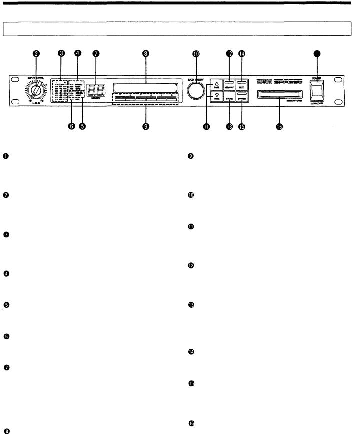
THE FRONT PANEL
Power Switch
Press to turn the power ON, press to turn the power OFF. When the power is turned ON, the last program and parameter selected will be automatically recalled.
Input Level Controls
These concentric controls vary the input levels of the analog inputs. The inner control adjusts the Lch level and the outer control the Rch level.
Input Level Meter
The stereo input level meter consists of eight Lch and Rch segments per channel, corresponding to -42dB, -36dB, -30dB, -24db, -18dB, -12dB, -6dB and Clip input.
Memory Area Indicator
The memory area have 3 indicators to be selected: PRESET, USER and CARD.
Input Select Indicator
The two input selections: STEREO or MONO can be chosen on the indicator (refer to page 9 for Input Select Indicator)
MIDI Indicator
The indicator will light up whenever a MIDI signal is inputed in the MIDI IN terminal.
LED MEMORY No. Display
When the LED display is continuously lit, the effect corresponding to the number displayed is active. When the LED display is flashing, this indicates a new memory location has been selected but has not been recall, leaving the previously selected effect active. When the recalling and storing are activated, it will light up.
LCD Display
The LCD displays the title of a selected effect, parameter value, messages, etc.
Assignable Function  Keys
Keys
The keys allow one touch direction to direct recall, activate selected effects and make parameter selection easy for edit mode. Press the keys to change the LCD display.
Data Entry Dial
The dial allows the change in program memory No. or parameter values.
Page Select  Keys
Keys
The keys allow step-wise selection of the menu numbers. Press the key corresponding to the direction in which you want increment or decrement.
Memory Mode Key and Indicator
This key is used to select a new memory location mode. The indicator will light up when the key is pressed. The key can also be used to select the indicator from the memory area.
Store Key
This key is used to store edited effect programs into one of the user memory location or the memory card by simply pressing the store key. (For program storage, refer to page 16.)
Edit Key and Indicator
Press this key to get the edit mode. When the edit mode is activated, the indicator will light up.
Bypass Key and Indicator
When the key is pressed, all unit effects are completely bypassed and the input signal is fed directly to the output. During bypassing, the indicator will light up.
Memory Card Slot
Optional memory card can be inserted in here to provide more locations.
4

THE REAR PANEL
L & R Input Connectors
These are the analog stereo inputs to the SPX990. The XLR- 3-31 type connector and TRS phone jacks are both electrical balanced input connectors. Refer to "SELECTING AN INPUT MODE" on page 9 when connecting to monaural output jacks.
Input Level Switch (+4dB/-20dB)
The level switch selects either -20dB or +4dB nominal input level.
L & R Output Connectors
These are the analog stereo output to the SPX990. The XLR- 3-32 type connector and TRS phone jacks are both electrical balanced output connectors.
Output Level Switch (+4dB/-20dB)
The switch selects either the -20dB or the +4dB nominal output level.
MIDI IN Terminal
This terminal is used to receive the MIDI signals from external MIDI devices.
MIDI OUT/THRU Terminals
OUT/THRU Switch
Selects either MIDI THRU or MIDI OUT operation for the MIDI OUT/THRU connector, described below.
MIDI OUT
When the switch controlling MIDI terminal is set at MIDI OUT, the internal data are fed to an external MIDI data recorder for storage.
MIDI THRU
When the switch is set at MIDI THRU, the terminal simply re-transmit data received at the MIDI IN terminal, allowing daisy-chaining to other MIDI devices.
Trigger Footswitch Jack
The footswitch jack can set parameters in a program and trigger effect programs. The footswitch jack accepts an optional Yamaha equivalent connector FC4 or FC5 for footcontrolled triggering of any effect program.
Bypass or INC/DEC Footswitch Jack
The following functions can be used to change the setting of the edit mode.
Bypass Function
When the optional footswitch FC4 or FC5 is connected to the jack, it can be used as the same function as in Bypass Key in
on the front panel.
Memory INC/DEC Function
When an optional footswitch FC4 or FC5 is connected to the jack, it can be used as a foot control to change program.
5

THE SPX990 SYSTEM
EFFECT CONFIGURATION
The SPX990 allows access to three separate groups of effect programs - pre-effect, main effect and post-effect.
It has 36 main effects, 4 pre-effects and 3 post-effects to select on. The pre and post-effects are equalizing and dynamic controls which play a role in the main effects.
These internal memory locations parameters provide flexibility in many ways we could enjoy.
6

MEMORY CONFIGURATION
In the SPX990, there are three memory areas in which a total of 280 programs can to fed into or recalled.
Preset Memory: No. 1-80 = 80 types
The preset memory contains 80 effect programs. (See page 12 for "Preset Program List") that you can select and use without modification. The preset programs themselves cannot be erased or changed in any way, but they can be edited and stored in the USER or CARD memory to create original variation.
User Memory : No. 1-99, 00 =100 types
The user memory provides 100 locations in which your own effect creations can be stored. You can edit a preset effect to create an original variation. At the time of purchase, storing of program is the same as that of the pre-set program.
Card Memory: No. 1-99,00=100 types
An optional memory card can be used to increase the memory locations or create a program library. The memory card can be used to edit and store a program just like the user memory locations and all the programs in the user memory locations can also be stored in the memory card.
MEMORY CARD
An optional Yamaha memory card MCD-32 or MCD-64 can hold up to 100 effects each to increase the memory storage of the programs. The card can store the user memory location programs or transfer its programs to the user memory.
Caution when using the memory card
•When you use the memory card for the first time, be sure to format it first. (See page 18)
•Do not pull out the card during recalling (see page 10), storing (see page 16), saving (see page 18) or loading (see page 18) of program. Also, do not pull out the card when the memory area indicator shows "CARD".
•The memory card cannot be stored or saved a program when the write protect switch is set at "ON". Also, the memory card
cannot be loaded once the user memory protect is set at  (See page 17)
• When operating a memory card, messages below will appear
on the LCD. |
|
When there is no memory card, |
will |
appear. |
|
During write protecting, |
will appear. |
When cards which cannot be used in the SPX990 are inserted or when cards are not initialized,
will appear.
7
MEMORY & EDIT MODES
There are two types of modes in this unit:
Memory Mode
This mode makes use of the effect program to recall that program. (see page 10). This mode normally appears when the power switch is ON.
Edit Mode
This mode set or edit the effect parameters. Press the EDIT key
to get this mode. There are 5 menu pages to this mode. |
|
For selection of pages, press the PAGE Select |
keys. |
Memory |
PRESET (No.1 ~ 80) |
|
Mode |
USER |
(No.1 ~ 99, 00) |
|
CARD |
(No.1 ~ 99, 00) |
Edit
Mode
NOTE: When storing an effect program, press the STORE key and the memory mode will return, (page 16) NOTE: If you want to get back to the memory mode from the edit mode, press the MEMORY key.
8

SELECTING AN INPUT MODE (Edit Mode: Page 5 menu)
We should try to understand input mode selection even though the preset effect program can be edited and stored.
The SPX990 inputs are stereo input connectors. However, signal from the left jack can be fed to both left and right channel processing circuitry and similarly, the signal from the right jack can be passed to the left and right channel processing circuitry.
Stereo
This is the normal mode of operation in which leftand rightchannel signals received at the leftand right-channel inputs are passed on to the SPX990 processing circuitry on the same channels as which they were received.
L Mono
This and the R Mono mode described below are ideal for use with monaural input and stereo inputs signal. In the L Mono mode, a monaural signal received at the INPUT L jack is fed to both the leftand right-channel processing circuitry and signal received at the INPUT R is ignored.
How to select an input mode
 Press the EDIT key to get the edit mode. Then use the PAGE Select
  keys to select of edit mode on the LCD display.
Press any function
to get the "Input Select" display.
R Mono
A monaural signal received at the INPUT R jack is fed to both the leftand right-channel processory circuitry and signal received at the INPUT L is ignored.
1 Press any function |
key under the LCD display |
|
to select the input mode |
NOTE: When you select the input mode to be  signal or signal even when connecting both the L and R terminals, monaural input signals will be transmitted.
NOTE: Input select mode is the same for all programs so they are stored even if the power switch is OFF,
 Press the EDIT key if you want to return to the
  of edit
mode or press the MEMORY key to return to the memory |
|
mode. |
9 |
|

GENERAL OPERATION
|
MEMORY RECALL |
There are 3 methods to recall a program; |
|
1. Recall by panel key .............. |
standard method. |
2. Direct recall........................... |
recall by simply pressing the function and keys. |
3.MIDI program change.............. recall by external MIDI devices.(see page 52)
1.How to recall a program by panel key
Press the MEMORY key to get the memory mode function. The memory indicator will light up.
Press the MEMORY key to select the desired "PRESET", "USER" or "CARD" you want from the memory area.
NOTE: Be sure to set the memory card in the card slot first before recalling any program from the memory area.
 Turn the DATA ENTRY dial to select the desired program memory No. The selected memory No. will flash on the display. The selected program title will be displayed on the LCD but actually, this is the previous program.
 Press the. function
 key under the LCD
 and the memory No. indication will light up and the program will be recalled. After recalling the program, the name of the main effect program will appear on the right side of the LCD.
Press the function  key under
  in the LCD if you want to cancel the recalling and the previous selected program will appear.
10

2. Direct Recall
Recalling can be done on any memory area program by simply pressing the function and keys if the direct recall function is been used.
The preset program No.1 can be recalled in the example below. However, by pressing the extreme left function key, the user memory No.5  program can also be recalled.
How to enter a memory No. for direct recall function
 Do the operations from steps
  in "1. How to recall a program by panel key" for recalling the desired program.
 When the memory No. flashes on the display, press the function key under the program No. you want to recall.
The desired memory No. will light up on the LCD display and the desired program No. on top of the pressed function key is recalled.
That is to say, the direct recalling takes one action to do three steps from in the "1. How to recall a program by panel key".
In order to do direct recalling, four function  keys from the left can be used. The four keys can be used for selection of any memory location. All stored program in any memory location will be saved even if the power switch is OFF.
NOTE: Direct recall can be used when a mode is at the memory mode function. Press the MEMORY key when a mode is at other mode function. (MEMORY indicator will light up)
NOTE: When doing direct recall from the memory card, insert the card into the slot first before pressing the function key. will appear if there is no memory card in the slot and programs cannot be recalled.
The letter in front of each two digits refers to:
 Other programs can also be done with other function keys in the same way.
11
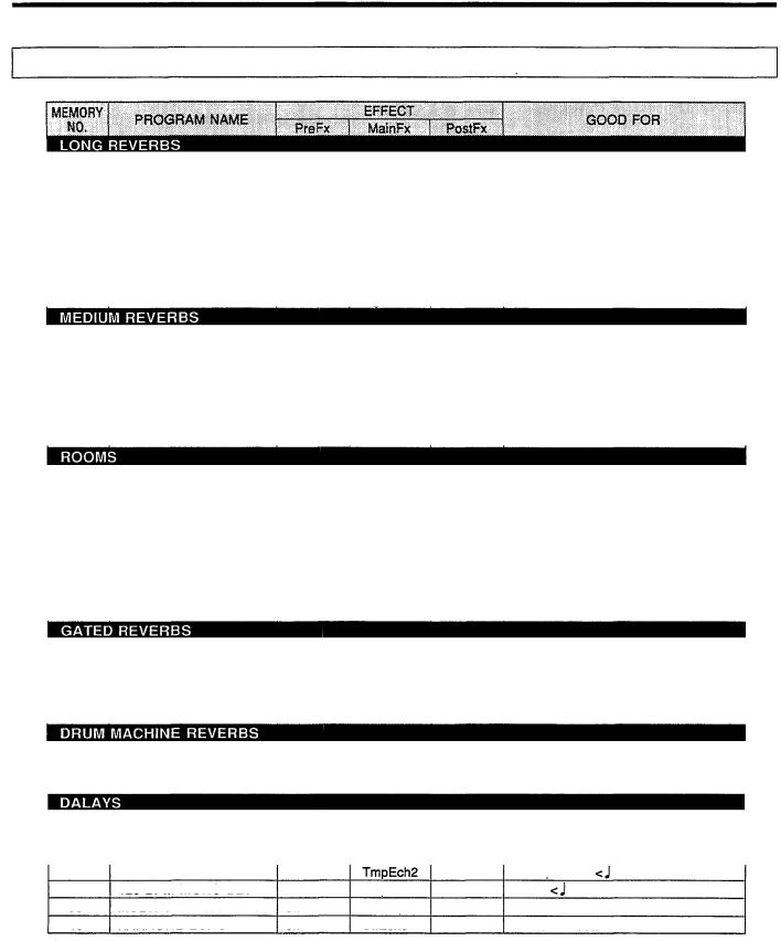
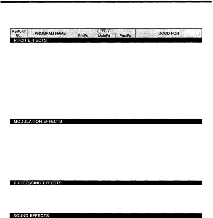
PRESET PROGRAM LIST
1 |
AMBIENCE |
P.EQ |
FiltRev |
off |
All |
|
|
2 |
STEREO HALL |
off |
St.Rev |
off |
E. Piano, Vocal |
|
|
3 |
DRUM CHAMBER |
P.EQ |
ER/Rev |
off |
ER for Tom / REV for Snare |
||
4 |
PLATE HALL |
off |
Rev/Rev |
off |
PLATE for Vocal, HALL for Inst. |
||
5 |
VOCAL CHAMBER |
off |
St.Rev |
Comp. |
Vocal |
|
|
6 |
BRIGHT HALL |
off |
FiltRev |
off |
All |
|
|
7 |
BREATHY REVERB |
P.EQ |
FiltRev |
HarmDr |
Male Vocal, Keyboard |
||
8 |
CONCERT HALL |
off |
Reverb |
off |
Keyboard (Pad) |
|
|
9 |
REVERB FLANGE |
off |
Flg&Rev |
P.EQ |
All |
|
|
|
|
|
|
|
|
|
|
10 |
VOCAL PLATE |
P.EQ |
Reverb |
P.EQ |
Vocal, All |
|
|
11 |
ECHO ROOM |
off |
EchRoom |
off |
All |
|
|
12 |
PRESENCE REVERB |
off |
FiltRev |
P.EQ |
Brass, Woodwind |
||
13 |
SNARE PLATE |
off |
FiltRev |
off |
Snare, |
Drums, |
Percussion |
14 |
ARENA |
off |
Reverb |
off |
Drums |
|
|
15 |
THIN PLATE |
off |
St.Rev |
P.EQ |
Vocal |
|
|
16 |
OLD PLATE |
P.EQ |
FiltRev |
off |
Snare |
|
|
|
|
|
|
|
|
|
|
17 |
FAT REFLECTIONS |
P.EQ |
FatER |
Comp. |
Drums, |
Percussion |
|
18 |
WOOD ROOM |
off |
EchRoom |
HarmDr |
Drums, |
Percussion |
|
19 |
BIG SNARE |
off |
GateRev |
off |
Snare |
|
|
20 |
BRIGHT SNARE |
P.EQ |
FiltRev |
Comp. |
Snare |
|
|
21 |
SQUASH ROOM |
P.EQ |
EchRoom |
Comp. |
Rock Drums, Guitar |
||
22 |
BAMBOO ROOM |
off |
EchRoom |
off |
Percussion |
|
|
23 |
REFLECTIONS |
off |
ThinER |
P.EQ |
All |
|
|
24 |
STONE ROOM |
off |
FiltRev |
P.EQ |
All |
|
|
25 |
CONCRETE ROOM |
off |
GateRev |
off |
Metal Guitar |
|
|
|
|
|
|
|
|
|
|
26 |
BLATTY PLATE |
P.EQ |
FiltRev |
P.EQ |
Drums |
|
|
27 |
FULL METAL GATE |
P.EQ |
GateRev |
P.EQ |
Drums |
|
|
28 |
HARD GATE |
P.EQ |
GateRev |
Comp. |
Snare |
|
|
29 |
REVERSE GATE |
P.EQ |
Reverse |
Comp. |
Guitar Solo, Vocal |
||
30 |
REVERSE PURPLE |
off |
Reverse |
P.EQ |
Drums |
|
|
|
|
|
|
|
|
|
|
31 |
DRUM MACH. AMB.S |
off |
St.Rev |
P.EQ |
Hi-hat, Snare |
|
|
32 |
DRUM MACH. AMB.L |
Off |
FiltRev |
off |
Percussion, Snare |
||
33 |
ELECT.SNR PLATE |
P.EQ |
Reverse |
Comp. |
Snare |
|
|
|
|
|
|
|
|
|
|
34 |
SYNC DELAY |
off |
TmpEch4 |
off |
Rock Vocal |
|
|
35 |
VOICE DOUBLER |
off |
DualPit |
off |
Vocal |
|
|
36 |
DELAY L, C, R |
off |
Dly-LCR |
off |
All |
|
|
37 |
120 BPM PAN DDL |
off |
TmpEch1 |
off |
Vocal. Hi-hat |
= 120> |
|
38 |
120 BPM MONO DLY |
off |
off |
Vocal |
= 120> |
||
39 |
MULTI TAP DELAY |
off |
MItTap |
P.EQ |
Vocal |
|
|
40 |
KARAOKE ECHO |
off |
StEcho |
P.EQ |
Karaoke Vocal |
|
|
12
41 |
GOOD OL P.CHANGE |
off |
DualPit |
Off |
All |
42 |
VOCAL SHIFT |
Comp. |
DualPit |
off |
Vocal, Backings |
43 |
AIRY PITCH |
HarmDr |
DualPit |
P.EQ |
Vocal |
44 |
ANALOGUE SLAP |
HarmDr |
DualPit |
P.EQ |
Vocal |
45 |
FAT BASS |
P.EQ |
TripPit |
off |
Synth Bass |
46 |
"LOW" SNARE |
P.EQ |
DualPit |
P.EQ |
Snare, Drums |
47 |
HALO COMB |
HarmDr |
DualPit |
Comp. |
Drums |
48 |
GRUMPY FLUTTER |
HarmDr |
DualPit |
P.EQ |
<Desending Pitch Effect> |
49 |
ROGER ON THE 12 |
off |
MonoPit |
off |
Guitar |
50 |
TWISTER |
off |
DualPit |
HarmDr |
Percussion |
51 |
BOTTOM WHACKER |
P.EQ |
DualPit |
off |
Drums |
52 |
INTELLICHORD MON |
off |
MonoPit |
off |
Guitar, Vocal <lnput mono tone> |
53 |
INTELLICHORD DUA |
off |
DualPit |
off |
Guitar, Vocal <lnput mono tone> |
54 |
INTELLICHORD TRI |
off |
TripPit |
off |
Guitar, Vocal <lnput mono tone> |
55 |
PITCH SLAP |
HarmDr |
DualPit |
off |
Vocal |
56 |
STEREO PITCH |
off |
StPitch |
off |
Vocal <Key shift> |
|
|
|
|
|
|
57 |
SYMPHONIC |
off |
Symphon |
off |
Guitar, Keyboard |
58 |
GTR SYM ECHO |
HarmDr |
Sym&Rev |
P.EQ |
Guitar, Keyboard |
59 |
CHORUS & REVERB |
off |
Cho&Rev |
Off |
Guitar, Keyboard |
60 |
BASS CHORUS |
off |
DualPit |
off |
Bass |
61 |
STEREO PHASING |
off |
Phaser |
off |
Guitar |
62 |
CLASSY GLASSY |
HarmDr |
FM.Cho |
P.EQ |
Keyboard (Pad) |
63 |
SILKY SWEEP |
HarmDr |
Phaser |
P.EQ |
All |
64 |
DETUNE CHORUS |
off |
DualFIg |
off |
All |
65 |
UP DOWN FLANGE |
P.EQ |
Flanger |
P.EQ |
Guitar |
66 |
UNDERWATER MOON |
P.EQ |
Cho/Rev |
HarmDr |
Keyboard (Pad), guitar |
67 |
TREMOLO |
off |
AutoPan |
off |
Guitar, Keyboard |
68 |
ROTARY SP. |
Dist. |
AM.Cho |
off |
Keyboard (Organ) |
|
|
|
|
|
|
69 |
FREEZE |
off |
Freeze |
off |
Sampling |
70 |
DIST. PERCUSSION |
Dist. |
ThinER |
Comp. |
Percussion |
71 |
DISTORTION 1 |
Dist. |
ThinER |
Comp. |
Bass, Vocal |
72 |
PAN |
off |
AutoPan |
off |
All |
73 |
TRIGGERED PAN |
off |
TrigPan |
off |
All |
74 |
PAN / PAN |
off |
Pan/Pan |
off |
Keyboard |
|
|
|
|
|
|
75 |
ON THE PHONE |
P.EQ |
Echo |
Comp. |
Telephone Voice |
76 |
IRON MAN |
P.EQ |
Dly-LCR |
Comp. |
Robot Voice |
77 |
RADIO BLAG |
P.EQ |
Flanger |
Off |
Radio Sound |
78 |
TUNNEL |
off |
EchRoom |
P.EQ |
Tunnel Reverb |
79 |
FOREVERVERB |
off |
St.Rev |
off |
Very Long Reverb |
80 |
SILVERHEART |
P.EQ |
Ech/Rev |
HarmDr |
Echo with Lots of Regeneration |
13

EDITING AN EFFECT PARAMETER MODE (Edit Mode: Page 1 menu)
Every program has different changeable parameters available in each effect. Original programs can be created by varying the parameters. The number of parameters and its type may be different to create an effect but the procedure for editing of a program is the same.
The procedure for editing parameters
Select and recall a desired program to be edited, (refer to "Memory Recall" on page 10)
Press the EDIT key to get the edit mode. The edit indicator will light up.
 The top line in the LCD display shows the parameter title and the bottom line shows each of its data.
Press any function or key under the parameter to be edited to change the data. The bracket will more according to the place where the function key is pressed.
Press the PAGE Select and |
keys to get the |
of the |
edit mode. |
|
|
 Press any function or key under the desired effect on the LCD display and the effect parameter to be edited will appear on Page 1. Page 1 shows each effect setting ofPreFx, MainFx and PostFx. (refer to "Selecting an Effect" on page 20)
Page1 of the effect parameter
 The parameter data can be changed by either the function
  or
or
 keys or by the DATA ENTRY dial.
NOTE: The parameter data changes very fast or slow depending on the speed of turning the DATA ENTRY dial.
Press the PAGE Select and keys and the menu screen to be edited will appear. Edit the parameter data from to The number of parameters and its variation are different to create a effect, (refer to "THE PROGRAMS & PARAMETERS" on page 20)
Press the EDIT key if you want to return to the edit mode on Other effect parameters can also be edited if neces-
sary.
The edited parameters data will not be lost even if the power switch is OFF but other programs not stored will be lost if the preset program is recalled. To store an edited data, you have to store the data into the user memory, (see page 16)
Press the MEMORY key to get back the memory mode again.
14
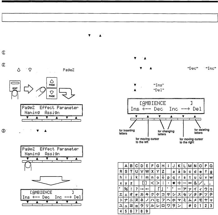
TITLE EDITING (Edit Mode: Page 2 menu)
You can title an effect program or change the original title (max. 16 letters) of an effect program that is edited by using the dial or the function and keys.
The procedure for naming a program
Select and recall a desired program to be edited, (refer to "Memory Recall" on page 10)
Press the EDIT key to get the edit mode and use the PAGE Select and keys to display the of the edit mode
 Shift the cursor on the top left line on the LCD by using the function and keys which are at the bottom of the
 position to select the letters. Letters can be changed by using
the function and keys at the bottom of |
and |
or by using the DATA ENTRY dial. |
|
The letters runs in sequence as shown below. Press the
function |
key under |
to insert any letter and press the |
function |
key under |
to delete any letter. |
Press any function or key under the display  which is on the bottom line of the LCD display to get the menu screen.
 The available letters are shown in sequence below.
 Store the effect program, (see page 16 for "STORING
PROGRAM")
15

STORING A PROGRAM
You can store original programs with changed parameters after recalling the programs from the three memory locations (preset, user and card) into the user memory location or the memory card.
Also, you can choose the desired program to be used in the three selections in the memory area and store in the user memory location or the memory card.
How to store a program
Set the user memory protect at OFF before storing a program. (refer to "SELECTING USER MEMORY PROTECT on page 17")
NOTE: You do not have to do this operation if the user memory protect mode is set at OFF.
NOTE: If the User memory protect is still ON after having stored a program, the STORE key been pressed by mistake, will not activate the storing.
If you want to store a desired program other than the one which is presently recalled, you can recall that desired program for storing.
Press the STORE key to execute  mode.
mode.
 Press the MEMORY key to select USER or CARD from the memory area location.
 Turn the DATA ENTRY dial to change and select the memory No. to be stored. The memory No. indicator will flash and the title of the program stored previously will appear on the LCD.
Press the function key under the display or the STORE key once again and the program stored previously will change to the desired program. The memory No. indicator will light up. Then the desired program recalled will be stored.
NOTE: When storing an edited program in the memory card, set the WRITE PROTECT switch at OFF first. Then, insert the card into the card slot before selecting the memory location, "CARD".
NOTE: You cannot store edited programs into the PRESET memory area location.
If you want to cancel any storing effect, press the function  key under the display
NOTE: The previous edited program stored will be lost if a new edited program with the same memory No. is been stored.
NOTE: You can do title editing on the new program, (refer to "TITLE EDITING" on page 15)
NOTE: You can store any parameter data regardless of the setting at ON/OFF for BYPASS mode.
NOTE: You can load all data in the memory card into the user memory location or load all data from the user memory location into the memory card. (refer to "SETTING OF MEMORY CARD on page 18")
16

SELECTING USER MEMORY PROTECT (Edit Mode: Page 5 menu)
You cannot store any edited data in the user memory location if the user memory protect is set at Pressing the STORE key by mistake will not activate the storing effect.
The procedure for user memory protect mode
Press the EDIT key to get the edit mode. Then use the PAGE
Select and keys to display the of the edit mode.
Press the any function or |
key at the bottom the LCD with |
to display the |
|
Select |
or |
by using the function and |
keys |
|
under the bracket display [ |
]. |
|
||
Press the EDIT key if you want to return to the |
of edit |
|||
mode or press the MEMORY key to return to the memory mode.
17
SETTING OF MEMORY CARD (Edit Mode: Page 4 menu)
The following steps show how to use a memory card:
• Format |
.....................................Format the MCD-64 or the MCD-32 memory card. |
• Save........................................ |
Copy and save all user memory data into the memory card. |
• Load......................................... |
Copy and load all memory card data into the user memory. |
How to set a memory card
Insert the MCD-64 or MCD-32 memory card well into the memory card slot.
Press the EDIT key to get the edit mode. Then press the PAGE Select and keys to display the of the edit mode.
and are indicated on the bottom line of the LCD. Press any function or key at the bottom of any desired operation to display the next screen.
Press the function  key under the display
  and the following operation will appear.
Press the function key under the display |
if you want |
to cancel the operation. |
|
 Press the EDIT key if you want to return to the
  of edit mode or press the MEMORY key to return to the memory mode.
NOTE: If you do formatting, the data stored in the memory now will be lost.
NOTE: If you do formatting and saving procedure, be sure to turn off the write protect switch in the memory card first. After you have done formatting and saving procedure, turn on the write protect switch.
18

SELECTING A FOOT SWITCH (BYPASS, INC/DEC TERMINAL) (Edit Mode: Page 5 menu)
The BYPASS, INC/DEC terminal in the rear panel can be connected to Yamaha's optional foot switch FC4 or FC5 and the following selection can be done:
• BYPASS function
This function serves the same operation as the BYPASS key on the front panel.
•Memory INC/DEC function
A selected program can be recalled within a certain range by using the foot switch. Every time the foot switch is been pressed on, a program will be changed.
NOTE: During performance, it will be very convenient if you can store the selected programs in sequence in the user memory or in the memory card.
How to operate the foot switch |
|
|
|
Press the EDIT key to get the edit mode. Then press the |
If you select the |
function, press the |
|
PAGE Select and keys to display the |
of the edit |
PAGE Select |
key to get to the next menu screen. |
menu. |
|
|
|
Press any function or key under the display |
to |
get to the foot switch function menu screen. |
|
Press any function |
or key on the left under the display to |
|
select either |
or |
function. |
Set the first program to be recalled by the left function keys. Then when you press the footswitch once the program set will be recalled. The memory No. is in two digits and the letter in front of the digits refers to USER and CARD.
Set the last program to be recalled by the right two function and keys. Then when you press the footswitch to the last program set, it will be recalled.
Press the EDIT key if you want to return to the of edit mode or press the MEMORY key to return to the memory mode.
In this operation, the program is automatically stored even if you do not press the STORE key.
•An example of a recalling range
Each program is changed in order of
19

THE PROGRAMS & PARAMETERS
In the SPX990, original programs can be created by editing the preset program. Therefore, it is important that we understand each and every preset program fundamentally in order to make full use of the effects.
Those parameters which have  mark cannot be controlled by MIDI parameter, (refer to page 56)
SELECTING AN EFFECT
As explained in the earlier section, one program is made up of 3 effects: pre-effect, main effect and the post effect.
There are together 4 kinds pre-effects, 36 kinds of main effects and 3 kinds of post effects.
Selecting an effect can be done on |
of the edit mode. (refer to "EDITING AN EFFECT PARAM- |
ETER MODE" on page 14.) |
|
PreFx, PostFx |
MainFx |
On/Off (Effect On/Off: ON, OFF)
This is the setting of the on/off function of the pre-/post effect.
Type (Effect Type: P.EQ, Comp., HarmDr, Dist.)
The following types of effects can be selected.
NOTE: Dist. effect cannot be selected in the post effect.
NOTE: Refer to "PRE & POST EFFECT PARAMETERS" for explanation on the effects.
StLink (Stereo Link: ON, OFF)
This is the On/Off function of the stereo link of Lch and Rch. When the function is set at ON, a channel's parameter value will be changed and set. At the same time another channel's parameter same value will also be set. In the case of the "Comp." effect, the compression parameters will be activated and both right and left channels stereo link will be done when the function is set at ON.
NOTE: There is no StLink parameter for the "Dist." effect.
NOTE: You cannot choose the main effects in the edit mode. Therefore, edit the desired effect program to make a original program.
On/Off (Main Effect On/Off: ON, OFF)
This is the setting of on/off function of the main effect.
Balance (Mix Balance: 0% ~ 100%)
This parameter adjusts the balance between the direct sound and effect signals. At 0%, only the direct sound is delivered from the SPX990 output while at 100%, only the effect sound isoutput.
Under the several effects, there are two types of effects having balance parameters.
On/Off (Main Effect On/Off: ON/OFF)
This is the setting of the on/off function of the main effects.
Balan 1 (Type 1 Mix Balance: 0% ~ 100%)
Balan 2 (Type 2 Mix Balance: 0% ~100%)
These parameters adjust balance between the direct sound and Type 1 effect sound  and direct sound and Type 2 effectsound
NOTE: Please refer to Type 1 and Type 2 effect sounds for explanation.
20
 Loading...