


I/O RACK
Owner’s Manual Bedienungsanleitung Mode d’emploi
Manual de instrucciones Manuale di istruzioni Руководство пользователя Manual do Proprietário
EN
DE
FR
ES
IT
RU
PT
JA
English
Español Français Deutsch
Português Русский Italiano
AUDIO INTERFACE

The above warning is located on the top of the unit.
L’avertissement ci-dessus est situé sur le dessus de l’unité.
Explanation of Graphical Symbols
Explication des symboles
The lightning flash with arrowhead symbol within an equilateral triangle is intended to alert the user to the presence of uninsulated “dangerous voltage” within the product’s enclosure that may be of sufficient magnitude to constitute a risk of electric shock to persons.
L’éclair avec une flèche à l’intérieur d’un triangle équilatéral est destiné à attirer l’attention de l’utilisateur sur la présence d’une « tension dangereuse » non isolée à l’intérieur de l’appareil, pouvant être suffisamment élevée pour constituer un risque d’électrocution.
The exclamation point within an equilateral triangle is intended to alert the user to the presence of important operating and maintenance (servicing) instructions in the literature accompanying the product.
Le point d’exclamation à l’intérieur d’un triangle équilatéral est destiné à attirer l’attention de l’utilisateur sur la présence d’instructions importantes sur l’emploi ou la maintenance (réparation) de l’appareil dans la documentation fournie.
IMPORTANT SAFETY
INSTRUCTIONS
1Read these instructions.
2Keep these instructions.
3Heed all warnings.
4Follow all instructions.
5Do not use this apparatus near water.
6Clean only with dry cloth.
7Do not block any ventilation openings. Install in accordance with the manufacturer’s instructions.
8Do not install near any heat sources such as radiators, heat registers, stoves, or other apparatus (including amplifiers) that produce heat.
9Do not defeat the safety purpose of the polarized or grounding-type plug. A polarized plug has two blades with one wider than the other. A grounding type plug has two blades and a third grounding prong. The wide blade or the third prong are provided for your safety. If the provided plug does not fit into your outlet, consult an electrician for replacement of the obsolete outlet.
10Protect the power cord from being walked on or pinched particularly at plugs, convenience receptacles, and the point where they exit from the apparatus.
11Only use attachments/accessories specified by the manufacturer.
12Use only with the cart, stand, tripod, bracket, or
table specified by the manufacturer, or sold with the apparatus. When a cart is used, use caution when moving the cart/apparatus combination to avoid injury from tip-over.
13 Unplug this apparatus during lightning storms or when unused for long periods of time.
14Refer all servicing to qualified service personnel. Servicing is required when the apparatus has been damaged in any way, such as powersupply cord or plug is damaged, liquid has been spilled or objects have fallen into the apparatus, the apparatus has been exposed to rain or moisture, does not operate normally, or has been dropped.
WARNING
TO REDUCE THE RISK OF FIRE OR ELECTRIC SHOCK, DO NOT EXPOSE THIS APPARATUS TO RAIN OR MOISTURE.
(UL60065_03)
PRÉCAUTIONS CONCERNANT LA SÉCURITÉ
1Lire ces instructions.
2Conserver ces instructions.
3Tenir compte de tous les avertissements.
4Suivre toutes les instructions.
5Ne pas utiliser ce produit à proximité d’eau.
6Nettoyer uniquement avec un chiffon propre et sec.
7Ne pas bloquer les orifices de ventilation. Installer l’appareil conformément aux instructions du fabricant.
8Ne pas installer l’appareil à proximité d’une source de chaleur comme un radiateur, une bouche de chaleur, un poêle ou tout autre appareil (y compris un amplificateur) produisant de la chaleur.
9Ne pas modifier le système de sécurité de la fiche polarisée ou de la fiche de terre. Une fiche polarisée dispose de deux broches dont une est plus large que l’autre. Une fiche de terre dispose de deux broches et d’une troisième pour le raccordement à la terre. Cette broche plus large ou cette troisième broche est destinée à assurer la sécurité de l’utilisateur. Si la fiche équipant l’appareil n’est pas compatible avec les prises de courant disponibles, faire remplacer les prises par un électricien.
10Acheminer les cordons d’alimentation de sorte qu’ils ne soient pas piétinés ni coincés, en faisant tout spécialement attention aux fiches, prises de courant et au point de sortie de l’appareil.
11Utiliser exclusivement les fixations et accessoires spécifiés par le fabricant.
12Utiliser exclusivement le chariot, le stand, le tré-
pied, le support ou la table recommandés par le fabricant ou vendus avec cet appareil. Si l’appareil est posé sur un chariot, déplacer le chariot avec précaution pour éviter tout risque de chute et de blessure.
13Débrancher l’appareil en cas d’orage ou lorsqu’il
doit rester hors service pendant une période prolongée.
14Confier toute réparation à un personnel qualifié. Faire réparer l’appareil s’il a subi tout dommage, par exemple si la fiche ou le cordon d’alimentation est endommagé, si du liquide a coulé ou des objets sont tombés à l’intérieur de l’appareil, si l’appareil a été exposé à la pluie ou à de l’humidité, si l’appareil ne fonctionne pas normalement ou est tombé.
AVERTISSEMENT
POUR RÉDUIRE LES RISQUES D’INCENDIE OU DE DÉCHARGE ÉLECTRIQUE, N’EXPOSEZ PAS CET APPAREIL À LA PLUIE OU À L’HUMIDITÉ.
(UL60065_03)
2 |
|
|
Owner’s Manual |
|
|
||
|
|
||
|
|
|
|
|
FCC INFORMATION (U.S.A.) |
|
|
|
1. |
IMPORTANT NOTICE: DO NOT MODIFY THIS UNIT! |
with FCC regulations does not guarantee that interference will |
|
|
|
This product, when installed as indicated in the instructions con- |
not occur in all installations. If this product is found to be the |
|
|
|
tained in this manual, meets FCC requirements. Modifications |
source of interference, which can be determined by turning the |
|
|
|
not expressly approved by Yamaha may void your authority, |
unit “OFF” and “ON”, please try to eliminate the problem by using |
|
|
|
granted by the FCC, to use the product. |
one of the following measures: |
|
|
2. IMPORTANT: When connecting this product to accessories |
Relocate either this product or the device that is being affected |
|
|
|
|
and/or another product use only high quality shielded cables. |
by the interference. |
|
|
|
|
|||
|
Cable/s supplied with this product MUST be used. Follow all |
Utilize power outlets that are on different branch (circuit breaker |
|
|
|
|
|||
|
installation instructions. Failure to follow instructions could void |
or fuse) circuits or install AC line filter/s. |
|
|
|
your FCC authorization to use this product in the USA. |
In the case of radio or TV interference, relocate/reorient the |
|
|
3. |
NOTE: This product has been tested and found to comply with |
|
|
|
antenna. If the antenna lead-in is 300 ohm ribbon lead, change |
|
|
||
|
the requirements listed in FCC Regulations, Part 15 for Class “B” |
the lead-in to co-axial type cable. |
|
|
|
digital devices. Compliance with these requirements provides a |
If these corrective measures do not produce satisfactory results, |
|
|
|
reasonable level of assurance that your use of this product in a |
|
|
|
|
please contact the local retailer authorized to distribute this type |
|
|
|
|
residential environment will not result in harmful interference with |
|
|
|
|
of product. If you can not locate the appropriate retailer, please |
|
|
|
|
other electronic devices. This equipment generates/uses radio |
contact Yamaha Corporation of America, Electronic Service Divi- |
|
|
|
frequencies and, if not installed and used according to the |
|
|
|
|
sion, 6600 Orangethorpe Ave, Buena Park, CA90620 |
|
|
|
|
instructions found in the users manual, may cause interference |
|
|
|
|
The above statements apply ONLY to those products distributed |
|
|
|
|
harmful to the operation of other electronic devices. Compliance |
|
|
|
|
by Yamaha Corporation of America or its subsidiaries. |
|
|
|
|
|
|
|
|
|
|
|
|
|
* This applies only to products distributed by YAMAHA CORPORATION OF AMERICA. |
(class B) |
|
||
|
|
|
|
|
COMPLIANCE INFORMATION STATEMENT (DECLARATION OF CONFORMITY PROCEDURE)
Responsible Party : Yamaha Corporation of America
Address : 6600 Orangethorpe Ave., Buena Park, Calif. 90620
Telephone : 714-522-9011
Type of Equipment : Audio Interface
Model Name : RSio64-D
This device complies with Part 15 of the FCC Rules.
Operation is subject to the following two conditions:
1)this device may not cause harmful interference, and
2)this device must accept any interference received including interference that may cause undesired operation.
See user manual instructions if interference to radio reception is suspected.
* This applies only to products distributed by YAMAHA CORPORATION OF AMERICA. (FCC DoC)
IMPORTANT NOTICE FOR THE UNITED KINGDOM
Connecting the Plug and Cord
WARNING: THIS APPARATUS MUST BE EARTHED IMPORTANT. The wires in this mains lead are coloured in accordance with the following code:
GREEN-AND-YELLOW : |
EARTH |
|
BLUE |
: |
NEUTRAL |
BROWN |
: |
LIVE |
As the colours of the wires in the mains lead of this apparatus may not correspond with the coloured markings identifying the terminals in your plug proceed as follows:
The wire which is coloured GREEN-and-YELLOW must be connected to the terminal in the plug which is marked by the letter E or by the safety earth symbol  or colored GREEN or GREEN-and-YELLOW.
The wire which is coloured BLUE must be connected to the terminal which is marked with the letter N or coloured BLACK.
The wire which is coloured BROWN must be connected to the terminal which is marked with the letter L or coloured RED.
(3 wires)
In Finland: Laite on liitettävä suojamaadoituskoskettimilla varustettuun pistorasiaan.
In Norway: Apparatet må tilkoples jordet stikkontakt.
In Sweden: Apparaten skall anslutas till jordat uttag.
(class I hokuo)
(B ), .
(class b korea)
|
Owner’s Manual |
|
3 |
|
|
||
|
|
||
|
|
|
|
Contents
PRECAUTIONS. . . . . . . . . . . . . . . . . . .5
Introduction |
8 |
Features ....................................................... |
8 |
Precautions for Rack Mounting .................... |
8 |
Firmware Updates........................................ |
8 |
Controls and Functions |
9 |
Front Panel .................................................. |
9 |
Rear Panel.................................................. |
12 |
Connections |
14 |
Installing a Mini-YGDAI card ...................... |
14 |
About Dante .............................................. |
14 |
Notes Regarding the Use of |
|
Network Switches ................................. |
15 |
About Dante Controller ............................. |
15 |
Connecting AC Power................................ |
15 |
Power on and off ....................................... |
15 |
Specifying the audio routing |
16 |
Editing the user pattern ............................. |
17 |
About R Remote V3 ................................... |
17 |
About the number of |
|
input/output channels........................... |
17 |
Word Clock |
18 |
Selecting a word clock source .................... |
18 |
About word clock ...................................... |
18 |
SRC (Sampling Rate Converter). . . .18
Other functions |
19 |
Remote control.......................................... |
19 |
IDENTIFY ................................................... |
19 |
Panel lock .................................................. |
19 |
Initializing the RSio64-D............................. |
20 |
Updating the RSio64-D’s |
|
hardware settings.................................. |
20 |
Troubleshooting . . . . . . . . . . . . . . . 21
Messages |
22 |
Error Messages........................................... |
22 |
Warning Messages ..................................... |
22 |
Information Messages ................................ |
23 |
Specifications . . . . . . . . . . . . . . . . 166
Dimensions . . . . . . . . . . . . . . . . . . 167
Block Diagram . . . . . . . . . . . . . . . 168
Various settings |
|
Specifying the RSio64-D’s word clock ........... |
18 |
Specifying the audio routing ........................ |
16 |
Specifying the ID that |
|
distinguishes the RSio64-D ...................... |
10 |
Specifying the UNIT ID range ....................... |
10 |
Specifying how the IP address is set.............. |
10 |
Specifying the type of |
|
connection to the Dante network ............ |
11 |
Initializing the RSio64-D ............................... |
20 |
Specifying the SRC word clock ..................... |
11 |
Included items (please check) |
|
• Owner’s manual |
|
• Power cord |
|
4 |
|
|
Owner’s Manual |
|
|
||
|
|
||
|
|
|
|

PRECAUTIONS
PLEASE READ CAREFULLY BEFORE PROCEEDING
Please keep this manual in a safe place for future reference.
 WARNING
Always follow the basic precautions listed below to avoid the possibility of serious injury or even death from electrical shock, short-circuiting, damages, fire or other hazards. These precautions include, but are not limited to, the following:
Power supply/power cord
•Do not place the power cord near heat sources such as heaters or radiators, and do not excessively bend or otherwise damage the cord, place heavy objects on it, or place it in a position where anyone could walk on, trip over, or roll anything over it.
•Only use the voltage specified as correct for the device. The required voltage is printed on the name plate of the device.
•Use only the supplied power cord/plug.
If you intend to use the device in an area other than in the one you purchased, the included power cord may not be compatible. Please check with your Yamaha dealer.
•Check the electric plug periodically and remove any dirt or dust which may have accumulated on it.
•When setting up the device, make sure that the AC outlet you are using is easily accessible. If you feel that a malfunction has occurred, immediately turn off the power, unplug the power cord plug from the electrical outlet, and also disconnect the connected power supply from the EXT DC INPUT jack. Even when the power switch is turned off, as long as the power cord is not unplugged from the wall AC outlet, the device will not be disconnected from the power source.
•Be sure to connect to an appropriate outlet with a protective grounding connection. Improper grounding can result in electrical shock, damage to the device(s), or even fire.
Do not open
•This device contains no user-serviceable parts. Do not open the device or attempt to disassemble the internal parts or modify them in any way. If it should appear to be malfunctioning, discontinue use immediately and have it inspected by qualified Yamaha service personnel.
Water warning
•Do not expose the device to rain, use it near water or in damp or wet conditions, or place on it any containers (such as vases, bottles or glasses) containing liquids which might spill into any openings. If any liquid such as water seeps into the device, turn off the power immediately and unplug the power cord from the AC outlet. Then have the device inspected by qualified Yamaha service personnel.
•Never insert or remove an electric plug with wet hands.
PA_en_4 1/2
Fire warning
•Do not put burning items, such as candles, on the unit. A burning item may fall over and cause a fire.
If you notice any abnormality
•When one of the following problems occur, immediately turn off the power switch and disconnect the electric plug from the outlet. Then have the device inspected by Yamaha service personnel.
-The power cord or plug becomes frayed or damaged.
-It emits unusual smells or smoke.
-Some object has been dropped into the device.
-There is a sudden loss of sound during use of the device.
•If this device should be dropped or damaged, immediately turn off the power switch, disconnect the electric plug from the outlet, and have the device inspected by qualified Yamaha service personnel.
 CAUTION
Always follow the basic precautions listed below to avoid the possibility of physical injury to you or others, or damage to the device or other property. These precautions include, but are not limited to, the following:
Power supply/power cord
•When removing the electric plug from the device or an outlet, always hold the plug itself and not the cord. Pulling by the cord can damage it.
•Remove the electric plug from the outlet when the device is not to be used for extended periods of time, or during electrical storms.
Location
•Do not place the device in an unstable position where it might accidentally fall over.
•Do not block the vents. This device has ventilation holes at the front/sides to prevent the internal temperature from becoming too high. In particular, do not place the device on its side or upside down. Inadequate ventilation can result in overheating, possibly causing damage to the device(s), or even fire.
•When installing the device:
-Do not cover it with any cloth.
-Do not install it on a carpet or rug.
-Make sure the top surface faces up; do not install on its sides or upside down.
-Do not use the device in a confined, poorly-ventilated location.
Inadequate ventilation can result in overheating, possibly causing damage to the device(s), or even fire.
•Do not place the device in a location where it may come into contact with corrosive gases or salt air. Doing so may result in malfunction.
•Before moving the device, remove all connected cables.
|
Owner’s Manual |
|
5 |
|
|
||
|
|
||
|
|
|
|

•When setting up the device, make sure that the AC outlet you are using is easily accessible. If some trouble or malfunction occurs, immediately turn off the power switch also disconnect the unit from the power supply that is connected to the EXT DC INPUT jack. Even when the power switch is turned off, electricity is still flowing to the product at the minimum level. When you are not using the product for a long time, make sure to unplug the power cord from the wall AC outlet.
•If the device is mounted in an EIA standard rack, carefully read the section “Precautions for Rack Mounting” on page 8. Inadequate ventilation can result in overheating, possibly causing damage to the device(s), malfunction, or even fire.
Connections
•Before connecting the device to other devices, turn off the power for all devices. Before turning the power on or off for all devices, set all volume levels to minimum.
Maintenance
•Periodically inspect and clean the air filter of the front panel ventilation opening (page 11). Dust and dirt can seriously degrade the effectiveness of the cooling fan and result in malfunction or fire.
•Remove the power plug from the AC outlet when cleaning the device.
Handling caution
•Do not insert your fingers or hands in any gaps or openings on the device (vents).
•Avoid inserting or dropping foreign objects (paper, plastic, metal, etc.) into any gaps or openings on the device (vents, etc.) If this happens, turn off the power immediately and unplug the power cord from the AC outlet. Then have the device inspected by qualified Yamaha service personnel.
•Do not rest your weight on the device or place heavy objects on it, and avoid use excessive force on the buttons, switches or connectors.
Yamaha cannot be held responsible for damage caused by improper use or modifications to the device, or data that is lost or destroyed.
PA_en_4 2/2
NOTICE
To avoid the possibility of malfunction/ damage to the product, damage to data, or damage to other property, follow the notices below.
Handling and maintenance
•Do not use the device in the vicinity of a TV, radio, stereo equipment, mobile phone, or other electric devices. Otherwise, the device, TV, or radio may generate noise.
•Do not expose the device to excessive dust or vibration, or extreme cold or heat (such as in direct sunlight, near a heater, or in a car during the day), in order to prevent the possibility of panel disfiguration, unstable operation, or damage to the internal components.
•Do not place vinyl, plastic or rubber objects on the device, since this might discolor the panel.
•When cleaning the device, use a dry and soft cloth. Do not use paint thinners, solvents, cleaning fluids, or chemicalimpregnated wiping cloths.
•Condensation can occur in the device due to rapid, drastic changes in ambient temperature—when the device is moved from one location to another, or air conditioning is turned on or off, for example. Using the device while condensation is present can cause damage. If there is reason to believe that condensation might have occurred, leave the device for several hours without turning on the power until the condensation has completely dried out.
•Always turn the power off when the device is not in use.
Information
About this manual
•The illustrations as shown in this manual are for instructional purposes only.
•The company names and product names in this manual are the trademarks or registered trademarks of their respective companies.
6 |
|
|
Owner’s Manual |
|
|
||
|
|
||
|
|
|
|
The model number, serial number, power requirements, etc., may be found on or near the name plate, which is at the top of the unit. You should note this serial number in the space provided below and retain this manual as a permanent record of your purchase to aid identification in the event of theft.
Model No.
Serial No.
(rear_en_01)
Information for Users on Collection and Disposal of Old Equipment
This symbol on the products, packaging, and/or accompanying documents means that used electrical and electronic products should not be mixed with general household waste.
For proper treatment, recovery and recycling of old products, please take them to applicable collection points, in accordance with your national legislation and the Directives 2002/96/EC.
By disposing of these products correctly, you will help to save valuable resources and prevent any potential negative effects on human health and the environment which could otherwise arise from inappropriate waste handling.
For more information about collection and recycling of old products, please contact your local municipality, your waste disposal service or the point of sale where you purchased the items.
[For business users in the European Union]
If you wish to discard electrical and electronic equipment, please contact your dealer or supplier for further information.
[Information on Disposal in other Countries outside the European Union]
This symbol is only valid in the European Union. If you wish to discard these items, please contact your local authorities or dealer and ask for the correct method of disposal.
(weee_eu_en_01)
European Models
Purchaser/User Information specified in EN55103-1:2009 and EN55103-2:2009. Inrush Current: 1.0A (on initial switch-on)
1.0A (after a supply interruption of 5s) Conforms to Environments: E1, E2, E3 and E4
|
Owner’s Manual |
|
7 |
|
|
||
|
|
||
|
|
|
|

Introduction
Introduction
Thank you for choosing the Yamaha RSio64-D audio interface.
To take full advantage of the superior functions and performance offered by the RSio64-D, and to enjoy years of trouble-free use, be sure to read this owner’s manual carefully before operation.
Features
The RSio64-D is an interface that can be used as a router and format converter between Dante and Mini-YGDAI cards.
This allows Mini-YGDAI cards that support a wide variety of input/output formats and processing to be connected to a Dante network, meeting the needs of various types of systems including broadcast, live, recording, and postproduction. In addition, the settings of the RSio64-D can be fully controlled from a CL or QL series console.
•A wide variety of Mini-YGDAI cards can be used, including processing cards as well as input/output cards.
•Each MY slot provides an SRC (Sampling Rate Converter) to allow digital connection between differing word clock routes.
•Seven different widely usable routing patterns are preset, including routing between Mini-YGDAI cards. Matrix patching from R Remote V3 or a CL/QL console.
•EXT DC INPUT supports redundant power supplies.
•Dante redundancy (primary/secondary) is supported.
NOTE
Before you install Mini-YGDAI cards in slots 1–4, you must check the Yamaha website to determine whether the card is compatible with the RSio64-D, and to verify the total number of Yamaha or third-party cards that can be installed in combination with that card.
Yamaha website:
http://www.yamahaproaudio.com/
Precautions for Rack
Mounting
This unit is rated for operation at ambient temperatures ranging from 0 to 40 degrees Celsius. When mounting the unit with other RSio unit(s) or other device(s) in an EIA standard equipment rack, internal temperatures can exceed the specified upper limit, resulting in impaired performance or failure. When rack mounting the unit, always observe the following requirements to avoid heat buildup:
•When mounting the unit in a rack with devices such as power amplifiers that generate a significant amount of heat, leave more than 1U of space between the RSio and other equipment. Also either leave the open spaces uncovered or install appropriate ventilating panels to minimize the possibility of heat buildup.
•To ensure sufficient airflow, leave the rear of the rack open and position it at least 10 centimeters from walls or other surfaces. If you’ve installed a fan kit, there may be cases in which closing the rear of the rack will produce a greater cooling effect. Refer to the rack and/or fan unit manual for details.
Firmware Updates
This product enables you to update the unit firmware to improve operations, add functions, and correct possible malfunctions. The following two types of firmware are available for the unit:
•Unit’s firmware
•Dante module firmware
Firmware updates are performed from R Remote V3. Details on updating the firmware are available on the following website:
http://www.yamahaproaudio.com/
For information on updating the unit, refer to the firmware update guide available on the website.
NOTE
It is necessary to update other devices depending on the version of each device in the Dante network. For details, refer to the firmware compatibility available on the Yamaha website.
http://www.yamahaproaudio.com/
8 |
|
|
Owner’s Manual |
|
|
||
|
|
||
|
|
|
|
Controls and Functions
Controls and Functions
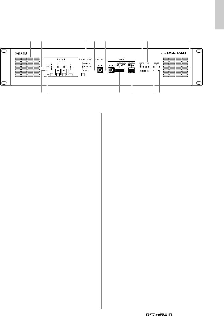
Front Panel
!3 q |
r t y |
o!0 |
!3 |
ON |
2 |
3 |
4 |
5 |
6 |
7 |
8 |
ON |
2 |
3 |
4 |
|
1 |
1 |
|
||||||||||
w e |
u |
|
|
i |
!1!2 |
|||||||
qSLOT 1–4 [LOCK] indicators
These indicate the word clock status of slots 1–4. The indicator is lit green if operation is normal.
Unlit |
No card is installed in the slot, or an unsup- |
|
ported card is installed. |
||
|
||
|
|
|
|
This indicates that a clock synchronized with |
|
|
the clock source selected by the WORD |
|
|
CLOCK select key is being input from the card. |
|
Green (lit) |
If an external device is connected to the corre- |
|
LOCK |
sponding slot, input/output is occurring cor- |
|
rectly between that device and the RSio64-D. |
||
|
If the sampling frequency is close, this status |
|
|
is shown in some cases even if not synchro- |
|
|
nized. |
|
|
|
|
|
A valid clock is being input from the card, but is |
|
Green |
not synchronized with the clock source |
|
selected by the WORD CLOCK select key. If |
||
(flashing) |
||
an external device is connected to the corre- |
||
|
||
SYNC |
sponding slot, input/output is not occurring |
|
correctly between that device and the RSio64- |
||
ERROR |
||
D. Input/output will occur correctly if SRC is |
||
|
||
|
turned ON. |
|
|
|
|
Red (lit) |
A valid clock is not being input from the card. If |
|
an external device is connected to the corre- |
||
|
||
UNLOCK |
sponding slot, input/output cannot occur cor- |
|
rectly between that device and the RSio64-D. |
||
|
||
|
|
|
|
The frequency of the clock source selected by |
|
Red |
the WORD CLOCK select key is outside the |
|
range of operating frequencies of the card |
||
(flashing) |
||
installed in the slot. Either set the frequency of |
||
|
||
WRONG |
the clock source to be within the operating |
|
range of the card, or turn SRC on. In the case |
||
WORD |
||
of an analog card, turning SRC on makes the |
||
CLOCK |
||
card operate at the RSio64-D’s internal fre- |
||
|
||
|
quency of 48 kHz. |
|
|
|
NOTE
•If the SLOT1–4 [LOCK] indicators and the SLOT1–4 [SRC] indicators and all WORD CLOCK indicators simultaneously flash red at startup, overcurrent has occurred in a MiniYGDAI card, or a malfunctioning Mini-YGDAI card is installed. Turn off the power and remove the card that is causing the problem.
•If the SLOT1–4 [LOCK] indicators and the SLOT1–4 [SRC] indicators alternately flash red at startup, the hardware settings of the RSio64-D need to be updated (page 20).
•If the SLOT1–4 [LOCK] indicators sequentially light green in the order of 1–4 at startup, the clocks of the slots are synchronizing. This may take several tens of seconds.
wSLOT 1–4 [SRC] indicators
These indicate the SRC (Sampling Rate Converter) status of slots 1–4.
Unlit |
SRC is off. |
|
|
|
|
Green (lit) |
SRC is on, and the clock selected by the SRC |
|
|
WCLK DIP switch is being input correctly. |
|
|
SRC is on, but an appropriate clock is not |
|
|
being input. It may be that the clock selected |
|
Red (lit) |
by the SRC WCLK DIP switch is not being |
|
input, or is outside the operating range. Either |
||
|
||
|
turn SRC off, or change the setting of the DIP |
|
|
switch. |
|
|
|
NOTE
The SRC clock sent to a Mini-YGDAI card installed in a slot is selected by the SRC WCLK DIP switch (page 11).
eSLOT 1–4 [SRC] keys
For each slot, these turn SRC on/off for the slot’s input as well as output.
|
Owner’s Manual |
|
9 |
|
|
||
|
|
||
|
|
|
|
 Loading...