


 Loading...
Owner’s Manual
Keep This Manual For Future Reference.
AUDIO INTERFACE
EN
Contents |
|
PRECAUTIONS................................... |
5 |
Introduction .................................... |
7 |
Features ............................................................. |
7 |
Firmware Updates.............................................. |
7 |
Precautions for Rack Mounting .......................... |
8 |
Recessed Installation .......................................... |
8 |
About Dante .................................... |
8 |
Caution when using a network switch................ |
8 |
Controls and Functions.................... |
9 |
Front Panel ........................................................ |
9 |
Rear Panel........................................................ |
11 |
Display Operations ........................ |
12 |
Operation Flow ................................................ |
12 |
Menu structure ................................................ |
12 |
Selecting menu items....................................... |
12 |
About the parameter display............................ |
12 |
Selecting ports ................................................. |
13 |
About port names............................................ |
13 |
METER menu ................................................... |
14 |
GAIN menu ..................................................... |
15 |
+48V ON menu ............................................... |
15 |
HPF ON menu ................................................. |
16 |
HPF F menu ..................................................... |
16 |
GC (Gain Compensation) ON menu ................ |
17 |
About the status indication .............................. |
17 |
SETUP menu .................................................... |
18 |
Status bar ........................................................ |
20 |
INFORMATION menu ...................................... |
21 |
Support for Dante Domain Manager |
|
(V1.10 or later) ......................................... |
22 |
Other functions................................................ |
24 |
About Connections ........................ |
25 |
Daisy Chain Network ....................................... |
25 |
Star Network.................................................... |
25 |
Dante Network Settings and Audio Routing ..... |
26 |
Head Amp Control ......................... |
26 |
Control from an Rio2-native Device.................. |
26 |
Head Amplifier Parameters That Can be |
|
Monitored and Controlled ........................ |
26 |
Troubleshooting ............................ |
27 |
Troubleshooting .............................................. |
27 |
Messages ......................................................... |
28 |
Specifications................................. |
31 |
General Specifications ...................................... |
31 |
Analog Input Characteristics............................. |
32 |
Analog Output Characteristics.......................... |
32 |
Digital I/O Characteristics ................................ |
32 |
Digital Output Characteristics .......................... |
32 |
Dimensions ...................................................... |
33 |
Accessories
(Please check the package contents.)
•Owner’s Manual
•AC power cord
•Dante Virtual Soundcard Token leaflet
2 |
|
|
|
|
|
|
|
|
|
Owner’s Manual |
|
|
|
|
|
|
|
||||
|
|
|
|
|
|
|
|
|
|
|
|
|
|
|
|
|
|
|
ATTENTION |
|
|
|
|
|
|
|
|
|||
|
|
|
|
|
|
|
|
|
|
|
|
|
|
|
|
|
|
RISQUE DE CHOC |
|
|
|
|
|
|
|
|
|||
|
|
|
|
|
|
|
|
ELECTRIQUE-NE PAS OUVRIR |
|
|
|
|
|
|
|
|
|
|
|
|
|
CAUTION: |
|
ATTENTION : |
|||||
TO REDUCE THE RISK OF ELECTRIC SHOCK, |
POUR RÉDUIRE LES RISQUES D'ÉLECTROCUTION, NE PAS RETIRER |
||||||||
DO NOT REMOVE COVER (OR BACK). |
LE CAPOT (OU LE DOS). NE CONTIENT PAS DE PIÈCES NÉCESSITANT |
||||||||
NO USER-SERVICEABLE PARTS INSIDE. |
L'INTERVENTION DE L'UTILISATEUR. POUR TOUTE INTERVENTION, |
||||||||
REFER SERVICING TO QUALIFIED SERVICE PERSONNEL. |
FAIRE APPEL À DES PROFESSIONNELS QUALIFIÉS. |
||||||||
The above warning is located on the rear of the unit. |
L’avertissement ci-dessus est situé sur l’arrière de l’unité. |
||||||||
Explanation of Graphical Symbols
Explication des symboles
The lightning flash with arrowhead symbol within an equilateral triangle is intended to alert the user to the presence of uninsulated “dangerous voltage” within the product’s enclosure that may be of sufficient magnitude to constitute a risk of electric shock to persons.
L’éclair avec une flèche à l’intérieur d’un triangle équilatéral est destiné à attirer l’attention de l’utilisateur sur la présence d’une
« tension dangereuse » non isolée à l’intérieur de l’appareil, pouvant être suffisamment élevée pour constituer un risque d’électrocution.
The exclamation point within an equilateral triangle is intended to alert the user to the presence of important operating and maintenance (servicing) instructions in the literature accompanying the product.
Le point d’exclamation à l’intérieur d’un triangle équilatéral est destiné à attirer l’attention de l’utilisateur sur la présence d’instructions importantes sur l’emploi ou la maintenance (réparation) de l’appareil dans la documentation fournie.
IMPORTANT SAFETY INSTRUCTIONS
1 Read these instructions.
2 Keep these instructions.
3Heed all warnings.
4Follow all instructions.
5 Do not use this apparatus near water.
6Clean only with dry cloth.
7Do not block any ventilation openings. Install in accordance with the manufacturer’s instructions.
8Do not install near any heat sources such as radiators, heat registers, stoves, or other apparatus (including amplifiers) that produce heat.
9Do not defeat the safety purpose of the polarized or groundingtype plug. A polarized plug has two blades with one wider than the other. A grounding type plug has two blades and a third grounding
prong. The wide blade or the third prong are provided for your safety. If the provided plug does not fit into your outlet, consult an electrician for replacement of the obsolete outlet.
10Protect the power cord from being walked on or pinched particularly at plugs, convenience receptacles, and the point where they exit from the apparatus.
11Only use attachments/accessories specified by the manufacturer.
12Use only with the cart, stand, tripod, bracket, or table specified by the manufacturer, or sold with
the apparatus. When a cart is used, use caution when moving the cart/apparatus combination to avoid injury from tip-over.
13 Unplug this apparatus during lightning storms or when unused for long periods of time.
14Refer all servicing to qualified service personnel. Servicing is required when the apparatus has been damaged in any way, such as power-supply cord or plug is damaged, liquid has been spilled or objects have fallen into the apparatus, the apparatus has been exposed to rain or moisture, does not operate normally, or has been dropped.
WARNING
TO REDUCE THE RISK OF FIRE OR ELECTRIC SHOCK, DO NOT EXPOSE THIS APPARATUS TO RAIN OR MOISTURE.
(UL60065_03)
PRÉCAUTIONS CONCERNANT LA SÉCURITÉ
1Lire ces instructions.
2Conserver ces instructions.
3 Tenir compte de tous les avertissements.
4Suivre toutes les instructions.
5Ne pas utiliser ce produit à proximité d’eau.
6Nettoyer uniquement avec un chiffon propre et sec.
7Ne pas bloquer les orifices de ventilation. Installer l’appareil conformément aux instructions du fabricant.
8Ne pas installer l’appareil à proximité d’une source de chaleur comme un radiateur, une bouche de chaleur, un poêle ou tout autre appareil (y compris un amplificateur) produisant de la chaleur.
9Ne pas modifier le système de sécurité de la fiche polarisée ou de la fiche de terre. Une fiche polarisée dispose de deux broches dont une est plus large que l’autre. Une fiche de terre dispose de deux broches et d’une troisième pour le raccordement à la terre. Cette broche plus large ou cette troisième broche est destinée à assurer la sécurité de l’utilisateur. Si la fiche équipant l’appareil n’est pas
compatible avec les prises de courant disponibles, faire remplacer les prises par un électricien.
10Acheminer les cordons d’alimentation de sorte qu’ils ne soient pas piétinés ni coincés, en faisant tout spécialement attention aux fiches, prises de courant et au point de sortie de l’appareil.
11Utiliser exclusivement les fixations et accessoires spécifiés par le fabricant.
12Utiliser exclusivement le chariot, le stand, le trépied, le support ou la table recommandés par
le fabricant ou vendus avec cet appareil. Si
l’appareil est posé sur un chariot, déplacer le chariot avec précaution pour éviter tout risque
de chute et de blessure. 13 Débrancher l’appareil en cas d’orage ou lorsqu’il
doit rester hors service pendant une période prolongée.
14Confier toute réparation à un personnel qualifié. Faire réparer l’appareil s’il a subi tout dommage, par exemple si la fiche ou le cordon d’alimentation est endommagé, si du liquide a coulé ou des objets sont tombés à l’intérieur de l’appareil, si l’appareil a été exposé à la pluie ou à de l’humidité, si l’appareil ne fonctionne pas normalement ou est tombé.
AVERTISSEMENT
POUR RÉDUIRE LES RISQUES D’INCENDIE OU DE DÉCHARGE ÉLECTRIQUE, N’EXPOSEZ PAS CET APPAREIL À LA PLUIE OU À L’HUMIDITÉ.
|
|
|
|
|
|
|
(UL60065_03) |
|
||
|
|
|
|
|
|
|
|
3 |
||
|
|
|
|
|
|
|
Owner’s Manual |
|
|
|
|
|
|
|
|
|
|
|
|
||
|
|
|
|
|
|
|
|
|
|
|

|
FCC INFORMATION (U.S.A.) |
||
1. |
IMPORTANT NOTICE: DO NOT MODIFY THIS UNIT! |
not guarantee that interference will not occur in all installations. If |
|
|
This product, when installed as indicated in the instructions con- |
this product is found to be the source of interference, which can be |
|
|
tained in this manual, meets FCC requirements. Modifications not |
determined by turning the unit “OFF” and “ON”, please try to elimi- |
|
|
expressly approved by Yamaha may void your authority, granted by |
nate the problem by using one of the following measures: |
|
|
the FCC, to use the product. |
Relocate either this product or the device that is being affected by |
|
2. IMPORTANT: When connecting this product to accessories and/ |
the interference. |
||
|
or another product use only high quality shielded cables. Cable/s |
Utilize power outlets that are on different branch (circuit breaker or |
|
|
supplied with this product MUST be used. Follow all installation |
fuse) circuits or install AC line filter/s. |
|
|
instructions. Failure to follow instructions could void your FCC |
In the case of radio or TV interference, relocate/reorient the |
|
|
authorization to use this product in the USA. |
||
|
antenna. If the antenna lead-in is 300 ohm ribbon lead, change the |
||
3. NOTE: This product has been tested and found to comply with the |
|||
lead-in to co-axial type cable. |
|||
|
requirements listed in FCC Regulations, Part 15 for Class “B” digital |
If these corrective measures do not produce satisfactory results, |
|
|
devices. Compliance with these requirements provides a reason- |
||
|
please contact the local retailer authorized to distribute this type of |
||
|
able level of assurance that your use of this product in a residential |
||
|
product. If you can not locate the appropriate retailer, please contact |
||
|
environment will not result in harmful interference with other elec- |
||
|
Yamaha Corporation of America, Electronic Service Division, 6600 |
||
|
tronic devices. This equipment generates/uses radio frequencies |
||
|
Orangethorpe Ave, Buena Park, CA90620 |
||
|
and, if not installed and used according to the instructions found in |
||
|
The above statements apply ONLY to those products distributed by |
||
|
the users manual, may cause interference harmful to the operation |
||
|
Yamaha Corporation of America or its subsidiaries. |
||
|
of other electronic devices. Compliance with FCC regulations does |
||
|
|
||
|
|
||
* This applies only to products distributed by YAMAHA CORPORATION OF AMERICA. |
(class B) |
||
COMPLIANCE INFORMATION STATEMENT (DECLARATION OF CONFORMITY PROCEDURE)
Responsible Party : Yamaha Corporation of America
Address : 6600 Orangethorpe Ave., Buena Park, Calif. 90620
Telephone : 714-522-9011
Type of Equipment : AUDIO INTERFACE
Model Name : Rio3224-D2/Rio1608-D2
This device complies with Part 15 of the FCC Rules.
Operation is subject to the following two conditions:
1)this device may not cause harmful interference, and
2)this device must accept any interference received including interference that may cause undesired operation.
See user manual instructions if interference to radio reception is suspected.
* This applies only to products distributed by |
(FCC DoC) |
YAMAHA CORPORATION OF AMERICA. |
|
4 |
|
|
|
|
|
|
|
|
|
Owner’s Manual |
|
|
|
|
|
|
|
||||
|
|
|
|
|
|
|
|
|
|
|
PRECAUTIONS
PLEASE READ CAREFULLY BEFORE PROCEEDING
Please keep this manual in a safe place for future reference.
 WARNING
Always follow the basic precautions listed below to avoid the possibility of serious injury or even death from electrical shock, short-circuiting, damages, fire or other hazards. These precautions include, but are not limited to, the following:
Power supply/power cord
•Do not place the power cord near heat sources such as heaters or radiators, and do not excessively bend or otherwise damage the cord, place heavy objects on it, or place it in a position where anyone could walk on, trip over, or roll anything over it.
•Only use the voltage specified as correct for the device. The required voltage is printed on the name plate of the device.
•Use only the supplied power cord/plug.
If you intend to use the device in an area other than in the one you purchased, the included power cord may not be compatible. Please check with your Yamaha dealer.
•Check the electric plug periodically and remove any dirt or dust which may have accumulated on it.
•Be sure to insert the power plug completely. Otherwise, electrical shock or fire might be caused.
•When setting up the device, make sure that the AC outlet you are using is easily accessible. If some trouble or malfunction occurs, immediately turn off the power switch and disconnect the plug from the outlet. Even when the power switch is turned off, as long as the power cord is not unplugged from the wall AC outlet, the device will not be disconnected from the power source.
•Remove the electric plug from the outlet when the device is not to be used for extended periods of time, or during electrical storms.
•Be sure to connect to an appropriate outlet with a protective grounding connection. Improper grounding can result in electrical shock, fire, or damage.
Shock hazard
Disconnect all power sources.
This device receives power from multi sources. When setting up the device, make sure that the AC outlet you are using is easily accessible. If some trouble or malfunction occurs, immediately turn off the power switch and disconnect the all plugs from the outlet. Even when the power switch is turned off, as long as the power cord is not unplugged from the wall AC outlet, the device will not be disconnected from the power source.
Do not open
•This device contains no user-serviceable parts. Do not open the device or attempt to disassemble the internal parts or modify them in any way. If it should appear to be malfunctioning, discontinue use immediately and have it inspected by qualified Yamaha service personnel.
Water warning
•Do not expose the device to rain, use it near water or in damp or wet conditions, or place on it any containers (such as vases, bottles or glasses) containing liquids which might spill into any openings. If any liquid such as water seeps into the device, turn off the power immediately and unplug the power cord from the AC outlet. Then have the device inspected by qualified Yamaha service personnel.
•Never insert or remove an electric plug with wet hands.
Hearing loss
•Before connecting the device to other devices, turn off the power for all devices. Also, before turning the power of all devices on or off, make sure that all volume levels are set to the minimum. Failing to do so may result in hearing loss, electric shock, or device damage.
•When turning on the AC power in your audio system, always turn on the power amplifier LAST, to avoid hearing loss and speaker damage. When turning the power off, the power amplifier should be turned off FIRST for the same reason.
Fire warning
•Do not place any burning items or open flames near the device, since they may cause a fire.
If you notice any abnormality
•If any of the following problems occur, immediately turn off the power switch and disconnect the electric plug from the outlet.
-The power cord or plug becomes frayed or damaged.
-Unusual smells or smoke are emitted.
-Some object has been dropped into the device.
-There is a sudden loss of sound during use of the device.
-Cracks or other visible damage appear on the device. Then have the device inspected or repaired by qualified Yamaha service personnel.
•If this device should be dropped or damaged, immediately turn off the power switch, disconnect the electric plug from the outlet, and have the device inspected by qualified Yamaha service personnel.
 CAUTION
Always follow the basic precautions listed below to avoid the possibility of physical injury to you or others, or damage to the device or other property. These precautions include, but are not limited to, the following:
Power supply/power cord
•When removing the electric plug from the device or an outlet, always hold the plug itself and not the cord. Pulling by the cord can damage it.
Location
•Do not place the device in an unstable position where it might accidentally fall over and cause injuries.
•Do not block the vents. This device has ventilation holes at the rear to prevent the internal temperature from becoming too high. In particular, do not place the device on its side or upside down. Inadequate ventilation can result in overheating, possibly causing damage to the device(s), or even fire.
•Do not place the device in a location where it may come into contact with corrosive gases or salt air. Doing so may result in malfunction.
|
|
|
|
|
|
|
Owner’s Manual |
|
5 |
|
|
|
|
|
|
|
|
||
|
|
|
|
|
|
|
|
|
|
•Before moving the device, remove all connected cables.
•If the device is mounted in an EIA standard rack, carefully read the section “Precautions for Rack Mounting” on page 8. Inadequate ventilation can result in overheating, possibly causing damage to the device(s), malfunction, or even fire.
Maintenance
•Remove the power plug from the AC outlet when cleaning the device.
Handling caution
•Do not insert your fingers or hands in any gaps or openings on the device (vents, etc.).
•Avoid inserting or dropping foreign objects (paper, plastic, metal, etc.) into any gaps or openings on the device (vents, etc.) If this happens, immediately turn off the power, unplug the power cord from the AC outlet, and have the device inspected by qualified Yamaha service personnel.
•Do not rest your weight on the device or place heavy objects on it. Avoid applying excessive force to the buttons, switches or connectors to prevent injuries.
•Avoid pulling the connected cables to prevent injuries or damage to the device.
Yamaha cannot be held responsible for damage caused by improper use or modifications to the device, or data that is lost or destroyed.
NOTICE
To avoid the possibility of malfunction/ damage to the product, damage to data, or damage to other property, follow the notices below.
Handling and maintenance
•Do not use the device in the vicinity of a TV, radio, AV equipment, mobile phone, or other electric devices. Otherwise, the device, TV, or radio may generate noise.
•Do not expose the device to excessive dust or vibration, or extreme cold or heat (such as in direct sunlight, near a heater, or in a car during the day), in order to prevent the possibility of panel disfiguration, unstable operation, or damage to the internal components.
•Do not place vinyl, plastic or rubber objects on the device, since this might discolor the panel.
•When cleaning the device, use a dry and soft cloth. Do not use paint thinners, solvents, cleaning fluids, or chemicalimpregnated wiping cloths.
•Condensation can occur in the device due to rapid, drastic changes in ambient temperature—when the device is moved from one location to another, or air conditioning is turned on or off, for example. Using the device while condensation is present can cause damage. If there is reason to believe that condensation might have occurred, leave the device for several hours without turning on the power until the condensation has completely dried out.
•Always turn the power off when the device is not in use.
Connectors
XLR-type connectors are wired as follows (IEC60268 standard): pin 1: ground, pin 2: hot (+), and pin 3: cold (-).
Information
About copyrights
*Copying of the commercially available musical data including but not limited to MIDI data and/or audio data is strictly prohibited except for your personal use.
About this manual
*The illustrations and LCD screens as shown in this manual are for instructional purposes only.
*The company names and product names in this manual are the trademarks or registered trademarks of their respective companies.
About the organic EL display
*Organic EL displays are created using extremely sophisticated technology. For this reason, there might be a very small number of picture elements that remain unlit or constantly lit. Also, you might notice line-shaped irregularities in color or brightness, or changes in color. Such things are due to the structure of an organic EL display, and are not malfunctions. Thank you for your understanding.
About disposal
This product contains recyclable components. When disposing of this product, please contact the appropriate local authorities.
European models
Purchaser/User Information specified in EN55103-2:2009.
Conforms to Environments: E1, E2, E3 and E4
Information for Users on Collection and Disposal of Old Equipment
This symbol on the products, packaging, and/or accompanying documents means that used electrical and electronic products should not be mixed with general household waste.
For proper treatment, recovery and recycling of old products, please take them to applicable collection points, in accordance with your national legislation and the Directives 2002/96/EC.
By disposing of these products correctly, you will help to save valuable resources and prevent any potential negative effects on human health and the environment which could otherwise arise from inappropriate waste handling.
For more information about collection and recycling of old products, please contact your local municipality, your waste disposal service or the point of sale where you purchased the items.
[For business users in the European Union]
If you wish to discard electrical and electronic equipment, please contact your dealer or supplier for further information.
[Information on Disposal in other Countries outside the European Union]
This symbol is only valid in the European Union. If you wish to discard these items, please contact your local authorities or dealer and ask for the correct method of disposal.
(weee_eu)
The model number, serial number, power requirements, etc., may be found on or near the name plate, which is at the rear of the unit. You should note this serial number in the space provided below and retain this manual as a permanent record of your purchase to aid identification in the event of theft.
Model No.
Serial No.
(rear_en_01)
6 |
|
|
|
|
|
|
|
|
|
Owner’s Manual |
|
|
|
|
|
|
|
||||
|
|
|
|
|
|
|
|
|
|
|

Introduction
Thank you for choosing the Yamaha Rio3224-D2/Rio1608-D2 I/O Rack. This product is a Dante-compatible I/O rack for use in a mixing system. The Rio3224-D2 is an I/O rack featuring 32 channels of analog input, 16 channels of analog output, and 8 channels of AES/EBU output. The Rio1608-D2 is an I/O rack featuring 16 channels of analog input and 8 channels of analog output. This manual explains the settings and troubleshooting that a mixing engineer or operator will perform when setting up or preparing the mixing system. In order to take full advantage of this product’s functionality, be sure to read this owner’s manual before use. After reading the manual, keep it for future reference.
NOTE
•Where specifications for the Rio3224-D2 differ from the Rio1608-D2, this manual places specifications that apply only to the Rio1608-D2 in curly brackets { } (e.g., [INPUT] connectors 1-32 {1-16}).
•Unless otherwise noted, illustrations for the Rio3224-D2 are used.
•If certain specifications are common to both the Rio3224-D2 and Rio1608-D2, both units are collectively called “Rio.”
Features
Long-distance Dante Network Capability
Low-latency, low-jitter audio can be transferred over distances up to 100 meters* between devices via standard Ethernet cables using the Dante network protocol. The Rio can be used as a general-purpose I/O box for the Dante network. Supported sampling rates are 44.1 kHz, 48 kHz, 88.2 kHz, and 96 kHz.
This unit supports the AES67 standard for audio networking interoperability, and allows audio connections via AES67 with various compatible audio networks.
* Maximum practical distance may vary according to the cable used.
Display and Encoder for Improved Visibility and Operability
The front panel features an organic EL display, an encoder with switch, and buttons. The internal head amps and parameters such as HPF can be viewed and controlled using only the Rio3224-D2/Rio1608-D2 unit itself. The unit’s internal errors and status are clearly indicated in the display.
Remotely Controllable Internal Head
Amplifiers
Internal head amp parameters can be remotely controlled from a compatible device such as the RIVAGE, CL, QL, or TF series, or from the Windows/Mac computer application “R Remote.”
Digital Outputs (Rio3224-D2 only)
The Rio3224-D2 features XLR-3-32 type balanced connectors for AES/EBU format digital audio outputs.
Introduction
Gain Compensation Function
If the Gain Compensation function of the Rio3224-D2/Rio1608-D2 is enabled from a supported device (such as a RIVAGE, CL, or QL series unit), the subsequent fluctuations in analog gain will be compensated for by the internal digital gain of the Rio3224-D2/Rio1608-D2, and the audio signal will be output to the Dante network at the gain level that was fixed immediately before the Gain Compensation function was enabled. This means that, for example, if the same inputs are shared by FOH and monitor, changing the FOH gain will not affect the monitor mix balance.
Two Internal Power Supply Units
Duplicate power supplies allow continued operation even in the unlikely event that one power supply experiences a problem.
Quietness
Noise-reduction measures for the fans provide greater silence.
Firmware Updates
This product enables you to update the unit firmware to improve operations, add functions, and correct possible malfunctions. The following two types of firmware are available for the unit.
•Unit’s firmware
•Dante module firmware
Details on updating the firmware are available on the following website:
https://www.yamaha.com/proaudio/
For information on updating and setting up the unit, please refer to the firmware update guide available on the website.
NOTE
When you update Dante firmware on the unit, be sure to update Dante firmware on other Dante-compatible devices connected to the Rio.
|
|
|
|
|
|
|
Owner’s Manual |
|
7 |
|
|
|
|
|
|
|
|
||
|
|
|
|
|
|
|
|
|
|
About Dante
Precautions for Rack Mounting
This unit is rated for operation at ambient temperatures ranging from 0 to 40 degrees Celsius. When mounting the unit with other Rio unit(s) or other device(s) in an EIA standard equipment rack, internal temperatures can exceed the specified upper limit, resulting in impaired performance or failure. When rack mounting the unit, always observe the following requirements to avoid heat buildup:
•If three or more Rio units are mounted without space in the same rack, set the fan speeds to HIGH.
•If multiple units are mounted in the same rack with their fan speeds set to LOW, leave a 1U rack space between every two units. Also either leave the open spaces uncovered or install appropriate ventilating panels to minimize the possibility of heat buildup.
•When mounting the unit in a rack with devices such as power amplifiers that generate a significant amount of heat, leave more than 1U of space between the Rio and other equipment. Also either leave the open spaces uncovered or install appropriate ventilating panels to minimize the possibility of heat buildup.
•To ensure sufficient airflow, leave the rear of the rack open and position it at least 10 centimeters from walls or other surfaces. If the rear of the rack can’t be left open, install a commercially available fan or similar ventilating option to secure sufficient airflow. If you’ve installed a fan kit, there may be cases in which closing the rear of the rack will produce a greater cooling effect. Refer to the rack and/or fan unit manual for details.
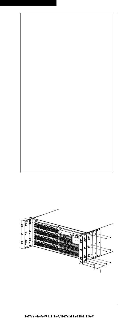
Recessed Installation
If you want to recess the front panel surface of the device from the front edge of the rack, you can adjust the position of the rack mount brackets to recess the device by 50mm or 100mm, as shown in the illustration below.
50 mm
100 mm
In the same way, rack mount hardware can also be attached to the rear panel surface.
NOTE
When you install the brackets, use the same screws that you just removed.
About Dante
Dante is a network audio protocol developed by the Audinate. Within a Giga-bit Ethernet (GbE), Dante delivers multi-channel audio signals at various sampling frequencies and bit rates, as well as device control signals.
Visit the Audinate website for more details on Dante. http://www.audinate.com/
More information on Dante is also posted on the Yamaha Pro Audio website:
https://www.yamaha.com/proaudio/
This product uses Dante Brooklyn2.
Refer to the Audinate website (English) for details on the open source licenses for the particular software.
https://www.audinate.com/software-licensing
Caution when using a network switch
Please do not use the EEE function (*) of network switches in a Dante network.
Although power management should be negotiated automatically in switches that support EEE, some switches do not perform the negotiation properly.
This may cause EEE to be enabled in Dante networks when it is not appropriate, resulting in poor synchronization performance and occasional dropouts.
Therefore we strongly recommend the following:
•When using a managed switch, turn off the EEE function of all ports used by Dante. Do not use a switch that is unable to turn off the EEE function.
•If using an unmanaged switch, do not use a switch that supports the EEE function. Such switches are unable to turn off the EEE function.
* EEE (Energy Efficient Ethernet) is a technology that reduces switch power consumption during periods of low network traffic. It is also known as Green Ethernet or IEEE802.3az.
8 |
|
|
|
|
|
|
|
|
|
Owner’s Manual |
|
|
|
|
|
|
|
||||
|
|
|
|
|
|
|
|
|
|
|

Controls and Functions
Controls and Functions
Front Panel
1 |
2 |
3 |
4 5 |
6 |
7 |
8 9 |
0 |
A |
B |
3 |
1[INPUT] Connectors 1–32 {1–16}
These are the XLR-3-31 type analog balanced connectors for the input channels. The input level range is from –62 dBu to +10 dBu. +48V phantom power can be supplied to devices that require it via the input connectors.
2[+48V] Indicators
These indicators light when +48V phantom power is turned ON for the corresponding input channels. On/off switching is controlled from this unit’s front panel display, or from a compatible digital mixer. No phantom power will be supplied, however, if the [+48V MASTER] switch is OFF, even if phantom power to individual channels is turned ON (the +48V indicators will flash). If a serious error occurs in this unit, the indicators of all channels will light or flash.
CAUTIONS:
•If phantom power is not required, you must turn OFF the +48V MASTER switch or the phantom power setting.
•When turning phantom power ON, make sure that no equipment other than phantom-powered devices such as condenser microphones are connected to the corresponding [INPUT] connectors. Applying phantom power to a device that does not require phantom power can damage the connected device.
•Do not connect or disconnect a device to an INPUT while phantom power is applied. Doing so can damage the connected device and/or the unit itself.
•To prevent possible damage to speakers, make sure that power amplifiers and/or powered speakers are turned OFF when switching phantom power ON or OFF. We also recommend setting all digital mixing console output controls to minimum when turning phantom power ON or OFF. Sudden high level peaks caused by the switching operation can damage equipment as well as the hearing of those present.
3[SIG] (Signal) Indicators
These indicators light green when the signal applied to the corresponding channel reaches or exceeds –40 dBFS.
If a serious error occurs in this unit, the indicators of all channels will light or flash.
4[PEAK] Indicators
These indicators light red when the signal level of the corresponding channel reaches or exceeds –3 dBFS. If a serious error occurs in this unit, the indicators of all channels will light or flash.
5Display
This shows information such as the parameter values of each port’s head amp, or error and status indications.
6 (DEC) button / (INC) button
Use these to move the cursor within the display.
7Encoder with switch
By turning this you can edit a parameter value shown in the display. By pressing the encoder you can select or confirm a setting, or switch the display.
8Power Indicator
Lights when AC power to the unit is ON.
|
|
|
|
|
|
|
Owner’s Manual |
|
9 |
|
|
|
|
|
|
|
|
||
|
|
|
|
|
|
|
|
|
|

Controls and Functions
9Power Switch (  )
)
Turns power to the unit ON or OFF.
CAUTIONS:
Even when the power switch is turned off, electricity is still flowing to the product at the minimum level. When you are not using the product for a long time, make sure to unplug the power cord from the wall AC outlet.
NOTE
Rapidly turning the unit on and off in succession can cause it to malfunction. After turning the unit off, wait for about 6 seconds before turning it on again.
0[+48V MASTER] Switch
This is the master switch for the unit’s +48V phantom power supply.
If the [+48V MASTER] switch is off, no phantom power will be supplied to the unit’s input connectors even if the individual input phantom power settings are ON. In this case, the [+48V] indicators will flash on channels for which phantom power is turned ON.
A[AES/EBU OUT] Connectors 1/2–7/8 (Rio3224-D2 only)
These XLR-3-32 type balanced connectors deliver AES/EBU format digital output from the unit’s corresponding output channels. Each connector outputs 2-channel digital audio.
B[OUTPUT +4 dBu] Connectors 1–16 {1–8}
These XLR-3-32 type balanced connectors deliver analog output from the unit’s corresponding output channels. Nominal output level is +4 dBu.
NOTICE:
If you cannot avoid connecting this unit’s balanced output to an unbalanced device, you should match the ground polarity of each unit, since differences in the ground polarity may cause a device to malfunction.
For the cable used to connect an unbalanced device, connect pin 3 COLD with pin 1 GND.
10 |
|
|
|
|
|
|
|
|
|
Owner’s Manual |
|
|
|
|
|
|
|
||||
|
|
|
|
|
|
|
|
|
|
|
Rear Panel
Rear Panel
C |
D |
E F |
G |
C[PRIMARY]/[SECONDARY] Connectors
These are etherCON (RJ45) ports can be connected to other Dante devices such as a RIVAGE, CL, QL, or TF series unit using Ethernet cables (CAT5e or better recommended). If the SETUP menu SECONDARY PORT parameter is set to DAISY CHAIN in the display, the signal that is input from one port is transmitted to the other port. Refer to “Daisy Chain Network” in the “About Connections” section (see page 25) for more information on daisy chain connections.
If the SETUP menu SECONDARY PORT parameter is set to REDUNDANT in the display, the [PRIMARY] port is for the primary connection and the [SECONDARY] port is for the secondary (backup) connection. If the unit is unable to transmit signals through the [PRIMARY] connector for some reason (e.g., due to damage or accidental removal of the cable, or a failed network switch), the [SECONDARY] connector will automatically take over the connection. Refer to “About Redundant Networks” in the “About Connections” section (see page 25) for more information on redundant networks.
NOTE
•The use of Ethernet cables with Neutrik etherCON CAT5e compatible RJ45 plugs is recommended. Standard RJ45 plugs can also be used.
•Use STP (shielded twisted pair) cable to prevent electromagnetic interference. Make sure that the metal parts of the plugs are electrically connected to the STP cable shield by conductive tape or comparable means.
•Connect only Dante-compatible devices or GbE-compatible devices (including a computer).
D[LINK/ACT] Indicators
These indicators show the communication status of the [PRIMARY] and [SECONDARY] connectors. They flash fast if the Ethernet cables are connected properly.
E[1G] Indicators
These indicators light when the Dante network is functioning as Giga-bit Ethernet.
FDIP switches
These are for expanding the functionality in the future. At present, no functions are assigned to these DIP switches.
GAC IN Connector
Connect the supplied AC power cord here. First, connect the power cord to the device, then insert the power cord plug into the AC outlet.
The supplied power cord features a special latching mechanism (V-LOCK) to prevent the power cord from being accidentally disconnected. Connect the power cord by inserting the power cord fully until it is locked.
CAUTION:
Be sure to turn the power off before connecting or disconnecting the power cord.
Press the latch button on the plug to disconnect the power cord.
Owner’s Manual 11
Loading...