


DIGITAL REVERBERATOR
Operation Manual
Manuel d’instructions
Bedienungsanleitung
Manual de Operación
|
|
|
|
|
|
|
DELAY |
|
DECAY |
|
LEVEL |
POWER |
|
PEAK |
|
|
|
|
|
|
|
||||
|
|
|
1-20 |
REVERB |
MIDI |
|
|
|
|
|
||
|
L |
R |
|
|
|
|
|
|
|
|||
|
|
|
21 -40 |
STEREO REV |
|
|
|
|
|
|
||
|
|
|
|
|
|
|
|
|
|
|
||
|
|
|
|
|
41 -50 |
GATE REV |
|
|
|
|
|
|
|
|
|
DIGITAL REVERBERATOR |
|
51 -60 |
DELAY |
STORE |
|
|
|
|
|
|
|
|
|
|
61 -70 |
DLY/REV |
|
|
|
|
|
|
|
|
|
|
|
71 -99 |
MOD/REV |
|
|
|
|
|
|
0 |
10 |
DRY |
WET |
INT |
PGM CHANGE |
MIN |
MAX |
MIN |
MAX |
MIN |
MAX |
|
|
|
|
MIDI |
|
|
|
|
|
|
|||
INPUT LEVEL |
MIX BALANCE |
|
|
|
PROGRAM |
|
|
|
|
|
||
ON |
OFF |

FCC INFORMATION (U.S.A.)
1.IMPORTANT NOTICE: DO NOT MODIFY THIS UNIT!
This product, when installed as indicated in the instructions contained in this manual, meets FCC requirements. Modifications not expressly approved by Yamaha may void your authority, granted by the FCC, to use the product.
2.IMPORTANT: When connecting this product to accessories and/or another product use only high quality shielded cables. Cable/s supplied with this product MUST be used. Follow all installation instructions. Failure to follow instructions could void your FCC authorization to use this product in the USA.
3.NOTE: This product has been tested and found to comply with the requirements listed in FCC Regulations, Part 15 for Class “B” digital devices. Compliance with these requirements provides a reasonable level of assurance that your use of this product in a residential environment will not result in harmful interference with other electronic devices. This equipment generates/uses radio frequencies and, if not installed and used according to the instructions found in the users manual, may cause interference harmful to the operation of other electronic devices. Compliance with FCC regulations does not guarantee that interference will not occur in all installations. If this product is found to be the source of interference, which can be determined by turning the unit “OFF” and “ON”, please try to eliminate the problem by using one of the following measures:
Relocate either this product or the device that is being affected by the interference
Utilize power outlets that are on different branch (circuit breaker of fuse) circuits or install AC line filter/s.
In the case of radio or TV interference, relocate/reorient the antenna. If the antenna lead-in is 300 ohm ribbon lead, change the lead-in to coaxial type cable.
If these corrective measures do not produce satisfactory results, please contact the local retailer authorized to distribute this type of product. If you can not locate the appropriate retailer, please contact Yamaha Corporation of America. Electronic Service Division, 6600 Orangethorpe Ave, Buena Park, CA 90620
*This applies only to products distributed by YAMAHA CORPORATION OF AMERICA
Dette apparat overholder det gaeldende EF-direktiv vedtrørende radiostøj.
Cet appareil est conforme aux prescriptions de la directive communautaire 87/308/CEE.
Diese Geräte entsprechen der EG-Richtlinie 82/499/EWG und/ oder 87/308/EWG.
This product complies with the radio frequency interference requirements of the Council Directive 82/499/EEC and/or 87/308/ EEC.
Questo apparecchio è conforme al D.M.13 aprile 1989 (Direttiva CEE/87/308) sulla soppressione dei radiodisturbi.
Este producto está de acuerdo con los requisitos sobre interferencias de radio frequencia fijados por el Consejo Directivo 87/308/CEE.
YAMAHA CORPORATION
IMPORTANT NOTICE FOR
THE UNITED KINGDOM
Connecting the Plug and Cord
WARNING: THIS APPARATUS MUST BE EARTHED
IMPORTANT: The wires in this mains lead are coloured in accordance with the following code:
GREEN-AND-YELLOW : EARTH
BLUE |
: NEUTRAL |
BROWN |
: LIVE |
As the colours of the wires in the mains lead of this apparatus may not correspond with the coloured markings idenlifying the terminals in your plug, proceed as follows:
The wire which is coloured GREEN and YELLOW must be connected to the terminal in the plug which is marked by the letter E or by the safety earth symbol or coloured GREEN and YELLOW.
The wire which is coloured BLUE must be connected to the terminal which is marked with the letter N or coloured BLACK.
The wire which is coloured BROWN must be connected to the terminal which is marked with the letter L or coloured RED.
* This applies only to products distributed by YAMAHA KEMBLE MUSIC (U.K.)
CANADA
THIS DIGITAL APPARATUS DOES NOT EXCEED THE “CLASS B” LIMITS FOR RADIO NOISE EMISSIONS
FROM DIGITAL APPARATUS SET OUT IN THE RADIO INTERFERENCE REGULATION OF THE CANADIAN DEPARTMENT OF COMMUNICATIONS.
LE PRESENT APPAREIL NUMERIQUE N’EMET PAS DE BRUITS RADIOELECTRIQUES DEPASSANT LES LIMITES APPLICABLES AUX APPAREILS NUMERIQUES DE LA “CLASSE B” PRESCRITES DANS LE REGLEMENT SUR LE BROUILLAGE RADIOELECTRIQUE EDICTE PAR LE MINISTERE DES COMMUNICATIONS DU CANADA.
*This applies only to products distributed by YAMAHA CANADA MUSIC LTD.
Litiumbatter!
Bör endast bytas av servicepersonal.
Explosionsfara vid felaktig hantering.
VAROITUS!
Lithiumparisto, Räjähdysvaara.
Pariston saa vaihtaa ainoastaan aian ammattimies.
ADVARSELl!
Lithiumbatter!
Eksplosionsfare. Udskiftning må kun foretages af en sagkyndig, –og som beskrevet i servicemanualen.
LTD.

Precautions
1.Location
Keep the unit away from locations where it is likely to be exposed to high temperatures or humidity — such as near radiators, stoves, etc. Also avoid locations which are subject to excessive dust accumulation or vibration which could cause mechanical damage and locations subject to strong electromagnetic fields, such as close to broadcast equipment.
2.Avoid Physical Shocks
Strong physical shocks to the unit can cause damage. Handle it with care.
3.Do Not Open the Case or Attempt Repairs or Modifications Yourself
This product contains no user-serviceable parts. Refer all maintenance to qualified Yamaha service personnel. Opening the case and/or tampering with the internal circuitry voids the warranty.
4.Always power off before making connections
Always turn the power OFF before connecting or disconnecting cables. This is important to prevent damage to the unit itself as well as other connected equipment.
5.Handle Cables Carefully
Always plug and unplug cables — including theAC power cord — by gripping the connector, not the cord.
6.Clean With a Soft Dry Cloth
Never use solvents such as benzine or thinner to clean the unit. Wipe clean with a soft, dry cloth.
7.Always Use the Correct Power Supply
The unit should only be powered using the supplied Yamaha AC Adaptor. The use of other adaptors can cause serious damage to the unit. Never use a cascade arrangement for the power supply connection from other equipment.

Introduction
The REV100 is a high-quality, inexpensive, and easy-to-use stereo Digital Reverberator. It can be used for home recording or smaller sound reinforcement applications. It is a true stereo processor with two inputs and two outputs.
Along with a high-quality stereo reverb, the REV100 offers delay-plus-reverb and modulation-plus-reverb effects. The 16-bit A/D and D/A converters provide superb sound quality and a wide frequency response due to the 44.1 kHz sampling rate.
The REV100 is simple to use, with rotary controls for setting levels and editing effect parameters. A MIDI IN connection is provided so that effects programs can also be selected using MIDI messages.
To take full advantage of your REV100, please read this manual thoroughly and keep it for future reference.
Contents
1. Controls . . . . . . . . . . . . . . . . . . . . . . 1
Front Panel . . . . . . . . . . . . . . . . . . . . . . . . . . . |
1 |
Rear Panel . . . . . . . . . . . . . . . . . . . . . . . . . . . . |
1 |
2. Operation . . . . . . . . . . . . . . . . . . . . 2
Installation and Connections . . . . . . . . . . . . . . 2
Changing Programs . . . . . . . . . . . . . . . . . . . . . 2
3. Edit Mode . . . . . . . . . . . . . . . . . . . . 6
Editing a Program . . . . . . . . . . . . . . . . . . . . . . 6
Storing a Program . . . . . . . . . . . . . . . . . . . . . . 6
Initializing the REV100 . . . . . . . . . . . . . . . . . 6
4. MIDI Mode . . . . . . . . . . . . . . . . . . 7
MIDI Program Change Table . . . . . . . . . . . . . 7 Setting the MIDI Program Change Table . . . . 7 Setting the MIDI Receive Channel . . . . . . . . . 8 Real-time Parameter Change . . . . . . . . . . . . . . 8 MIDI Data Format . . . . . . . . . . . . . . . . . . . . . . 9
5. Specifications . . . . . . . . . . . . . . . . 10
General specifications . . . . . . . . . . . . . . . . . . 10
Dimensions . . . . . . . . . . . . . . . . . . . . . . . . . . 10
MIDI Implementation Chart

Controls
1. Controls
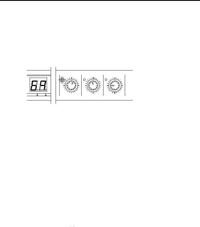
Front Panel
1 2 3 |
4 |
5 |
6 |
7 |
|
|
|
|
|
|
|
DELAY |
|
DECAY |
|
LEVEL |
POWER |
|
|
PEAK |
|
|
|
|
|
|
|
|
||||
|
|
|
1-20 |
REVERB |
MIDI |
|
|
|
|
|
|
||
|
L |
R |
|
|
|
|
|
|
|
|
|||
|
|
|
21-40 |
STEREO REV |
|
|
|
|
|
|
|
||
|
|
|
|
|
|
|
|
|
|
|
|
||
|
|
|
|
|
41-50 |
GATE REV |
|
|
|
|
|
|
|
|
|
|
DIGITAL REVERBERATOR |
|
51-60 |
DELAY |
STORE |
|
|
|
|
|
|
|
|
|
|
|
61-70 |
DLY/REV |
|
|
|
|
|
|
|
|
|
|
|
|
71-99 |
MOD/REV |
|
|
|
|
|
|
|
0 |
10 |
DRY |
WET |
INT |
PGM CHANGE |
MIN |
MAX |
MIN |
MAX |
MIN |
MAX |
|
|
|
|
|
MIDI |
|
|
|
|
|
|
|
|||
INPUT LEVEL |
MIX BALANCE |
|
|
|
PROGRAM |
|
|
|
|
ON |
OFF |
||
|
|
|
|
|
|
|
|
|
|
|
|
||
1 INPUT LEVEL control
This rotary control sets the input level. You should set the level so that the PEAK (L/R) indicators only flash occasionally.
2 PEAK (L/R) indicators
These LEDs will light when the REV100 is receiving a peak level signal.
3 MIX BALANCE (DRY/WET) control
bers. When you select the MIDI Program Change table, the MIDI indicator will light, and when you select the internal programs, the INT indicator will light. Refer to “Setting the MIDI Program Change Table” on page 7.
5 PROGRAM (  ,
,  , MIDI, STORE) keys
These keys allow you to select the different programs, edit the MIDI Program Change table, and store modified programs.
6 Edit (DELAY, DECAY, LEVEL) controls
This rotary control sets the balance of wet (effect) and dry (no effect) sounds.
4LED display (7-segment LED, MIDI indicator, INT indicator)
This 7-segment display indicates the current program in Program Mode. It shows the value of parameters when the REV100 is in Edit Mode and it shows MIDI program num-
These rotary controls edit the amount of parameters of the current effect. When the edited value of a parameter is the same as the currently saved value, the LED to the left of the control will light. Refer to “Editing a Program” on page 6.
7POWER switch
Press this switch ON to turn on the power.
Rear Panel
12
DC 12V IN |
MIDI IN |
34
|
OUTPUT |
|
INPUT |
R |
L(MONO) |
R |
L(MONO) |
1DC 12V IN inlet
The supplied AC Adapter is plugged into this connector.
2MIDI IN connector
The REV100 receives MIDI data via this connection.
3 OUTPUT connectors
4INPUT connectors
These 1/4" phone connectors are used to plug a sound source into the REV100. If the source is monophonic, plug the jack into the L-MONO connection only.
These 1/4" phone connectors are used to output the processed sound from the REV100. If you are using it monophonically, plug a jack into the L-MONO connection only.
1

Operation
2. Operation
Installation and Connections
Install the REV100 in a rack or place it in a location where it is safe and stable. Connect the AC Adapter to the DC 12V IN inlet, then plug the Adapter into a mains supply. To prevent the power from being accidentally disconnected, hook the cable around the anchor.
Press the POWER switch to turn the REV100 on.
Changing Programs
Select the different programs by pressing the  and
and  keys. The REV100 has 99 programs for you to select from.
REVERB
DC 12V IN
MODEL |
DIGITAL |
|
MADE |
|
REV100 |
|
IN |
|
|
|
JAPAN |
No |
Name |
Type |
Description |
|
|
|
|
|
|
1 |
Vocal Rev 1 |
Vocal |
Reverberation suitable for vocals |
|
|
|
|
|
|
2 |
Vocal Rev 2 |
Hall |
No.3 has a longer pre-delay and shorter reverb time |
|
|
|
|
||
3 |
Vocal Rev 3 |
Vocal |
||
|
||||
|
|
|
|
|
4 |
Room Ambience 1 |
|
|
|
|
|
|
|
|
5 |
Room Ambience 2 |
Plate |
These are mainly for drums and percussions. You can use them for |
|
|
|
|
||
|
|
|
||
6 |
Room Ambience 3 |
|
the entire drum kit or a single drum sound such as snare, bass drum, |
|
|
|
|
etc. |
|
7 |
Wood Booth 1 |
|
||
|
|
|||
|
|
|
|
|
8 |
Wood Booth 2 |
Vocal |
|
|
|
|
|
|
|
9 |
Acoustic Piano Plate |
|
Reverberation for acoustic piano |
|
|
|
|
||
10 |
Club Piano |
Hall |
||
|
||||
|
|
|
||
11 |
Booming Kick 1 |
Reverberation for bass drum, with an emphasized low range |
||
|
||||
|
|
|
||
12 |
Booming Kick 2 |
Room |
||
|
||||
|
|
|
||
13 |
Loud Snare |
Reverberation for louder snare |
||
|
||||
|
|
|
|
|
14 |
Acoustic Steel Guitar 1 |
|
Reverberation for steel-string acoustic guitar |
|
|
|
|
||
15 |
Acoustic Steel Guitar 2 |
Plate |
||
|
||||
|
|
|
|
|
16 |
String Plate |
|
Reverberation mainly used for strings |
|
|
|
|
|
|
17 |
Acoustic Gut Guitar 1 |
Vocal |
Reverberation for nylon-string acoustic guitar |
|
|
|
|||
18 |
Acoustic Gut Guitar 2 |
|||
|
|
|||
|
|
|
|
|
19 |
Brass Room 1 |
Room |
Brighter and shorter reverb for brass section |
|
|
|
|||
20 |
Brass Room 2 |
|||
|
|
|||
|
|
|
|
2

Operation
STEREO REVERB
No |
Name |
Type |
Description |
|
|
|
|
|
|
|
|
|
|
21 |
Large Hall 1 |
|
|
|
|
|
|
|
|
|
|
|
|
22 |
Large Hall 2 |
Hall |
These are hall-type reverb variations.”Stage” reverbs are brighter than |
|
|
|
|
|
|
|
|||
23 |
Stage 1 |
“Hall” reverbs |
|
|
||
|
|
|
||||
|
|
|
|
|||
|
|
|
|
|
|
|
24 |
Stage 2 |
|
|
|
|
|
|
|
|
|
|
|
|
25 |
Chamber 1 |
Vocal |
|
|
|
|
|
|
|
|
|
|
|
26 |
Chamber 2 |
Hall |
Image of a large chamber with a high ceiling |
|
|
|
|
|
|
|
|
||
27 |
Church 1 |
Room |
|
|
||
|
|
|
||||
|
|
|
|
|
|
|
28 |
Church 2 |
Hall |
|
|
|
|
|
|
|
|
|
|
|
29 |
Old Tunnel |
Hall |
Simulates sound inside a long tunnel. “Old” is dark and “New” is bright |
|||
|
|
|
||||
30 |
New Tunnel |
Vocal |
||||
|
|
|
||||
|
|
|
|
|
|
|
31 |
Large Room 1 |
|
Room-type simulation. No.32 contains more low range than No.31 |
|||
|
|
|
||||
32 |
Large Room 2 |
|
||||
|
|
|
|
|||
|
|
|
|
|
|
|
33 |
Slide Reverb |
Room |
Reverb sound is panned to right |
|||
|
|
|
|
|
|
|
34 |
Huge Room 1 |
|
More dynamic than a room-type reverberation |
|||
|
|
|
||||
35 |
Huge Room 2 |
|
||||
|
|
|
|
|||
|
|
|
|
|
|
|
36 |
Bathroom |
Plate |
Very short stereo reverb |
|||
|
|
|
|
|
||
37 |
String Ensemble |
Spacious reverb suitable for strings |
||||
|
||||||
|
|
|
|
|
|
|
38 |
Rude Reverb 1 |
|
Rough reverberation |
|||
|
|
|
||||
39 |
Rude Reverb 2 |
Vocal |
||||
|
|
|
||||
|
|
|
|
|
|
|
40 |
Concert Grand Piano |
|
Suitable for an acoustic piano |
|||
|
|
|
|
|
|
|
GATE REVERB |
|
|
|
|
||
|
|
|
|
|
||
No |
Name |
Type |
Description |
|
|
|
|
|
|
|
|
|
|
41 |
Small Ambience 1 |
Hall |
Simulates a room with smaller reflections. No.42 has been made by |
|
|
|
|
|
|
||||
42 |
Small Ambience 2 |
cutting the low range of No.41 |
|
|
||
|
|
|||||
|
|
|
|
|||
|
|
|
|
|
|
|
43 |
Tight Room 1 |
Room |
Simulates a room smaller than “Small Ambience” reverbs |
|
|
|
|
|
|
|
|||
44 |
Tight Room 2 |
Hall |
|
|
||
|
|
|
||||
|
|
|
|
|
|
|
45 |
Gate Reverb 1 |
Plate |
|
|
|
|
|
|
|
|
|
|
|
46 |
Gate Reverb 2 |
Vocal |
Gate reverb variations |
|
|
|
|
|
|
|
|||
47 |
Gate Reverb 3 |
Hall |
|
|
||
|
|
|
||||
|
|
|
|
|
||
48 |
Gate Reverb 4 |
|
|
|
||
|
|
|
|
|||
|
|
|
|
|
||
49 |
Stone Room |
Room |
Simulates a room made of stone |
|
|
|
|
|
|
|
|
||
50 |
Big Curve |
Vocal |
The longest reverb in the gate reverbs |
|
|
|
|
|
|
|
|
|
|
3

Operation
DELAY
No |
Name |
Description |
|
|
|
|
|
51 |
Analog Delay 1 |
Soft delay sound |
|
|
|
|
|
52 |
Ping Pong Delay |
Delay sound is panned between left and right |
|
|
|
|
|
53 |
Eighth Note Triplet |
Ping-pong delay that sounds like eight note triplets |
|
|
|
|
|
54 |
Karaoke |
Echo used for Karaoke |
|
|
|
|
|
55 |
Short Delay Doubler |
Very short, one-time delay |
|
|
|
|
|
56 |
Stereo Long Delay |
Stereo delay with the same length for the left and right channels |
|
|
|
|
|
57 |
Stereo Medium Delay |
Stereo delay with different length channels |
|
|
|
|
|
58 |
Stereo Short Delay |
Short delay with the same length channels |
|
|
|
|
|
59 |
Mono Long Delay |
Repeat delay with mono output |
|
|
|
||
60 |
Mono Short Delay |
||
|
|||
|
|
|
DELAY/REVERB
No |
Name |
|
Type |
Description |
|
|
|
|
|
||
61 |
Electric Piano |
DLY+Hall |
Mainly used for electric pianos |
||
|
|
|
|
|
|
62 |
String Pad |
DLY→ |
Hall |
Suitable for pad-type sound |
|
|
|
|
|
|
|
63 |
Synth |
DLY→ |
Vocal |
Suitable for pad strings |
|
|
|
|
|||
64 |
Vocal 1 |
|
|||
|
|
|
|||
|
|
|
|
Preset No.64 and No.65 are longer reverbs with a slight delay, suit- |
|
65 |
Vocal 2 |
DLY→ |
Hall |
||
able for vocal. Preset No.66 is a short reverb, with delay emphasized |
|||||
|
|
|
|
||
66 |
Vocal 3 |
DLY+ |
Room |
|
|
|
|
|
|
|
|
67 |
Bright Vocal |
DLY→ |
Plate |
Bright reverb, with very subtle delay |
|
|
|
|
|
||
68 |
Chorus |
DLY+Plate |
50% of delay and 50% of reverb are combined |
||
|
|
|
|
||
69 |
Drum Kit 1 |
DLY+Room |
Ambience effect for drums and percussion |
||
|
|
|
|
||
70 |
Drum Kit 2 |
DLY→ |
Plate |
||
|
|||||
|
|
|
|
|
|
REVERB/MODULATION
No |
Name |
Type |
Description |
||
|
|
|
|
|
|
71 |
Soft Flange 1 |
Hall+FLG |
This effect combines thin flanging effect with a small pitch variation, |
||
|
|
||||
72 |
Soft Flange 2 |
and reverberation, suitable for pad-type synth sounds |
|||
|
|
||||
|
|
|
|||
|
|
|
|
|
|
73 |
Ambience Flange 1 |
|
|
Flanging effect has been added to a short reverb |
|
|
|
|
|
||
74 |
Ambience Flange 2 |
Room→ |
FLG |
||
|
|||||
|
|
|
|||
75 |
Short Reverb Flange |
|
|
A very short reverb has been added to the flange effect with a larger |
|
|
|
pitch variation |
|||
|
|
|
|
||
|
|
|
|
|
|
76 |
Organ Cabinet 1 |
Plate→ |
FLG |
Flange effect suitable for organ sounds |
|
|
|
|
|
||
77 |
Organ Cabinet 2 |
Room→ |
SYM |
||
|
|||||
|
|
|
|
||
78 |
Symphonic Reverb 1 |
Hall+SYM |
Elegant effect mainly based on reverberation |
||
|
|
|
|
||
79 |
Symphonic Reverb 2 |
Vocal+SYM |
|||
|
|||||
|
|
|
|
|
|
4

Operation
REVERB/MODULATION
No |
Name |
Type |
Description |
|
|
|
|
|
|
80 |
Flange Room 1 |
Vocal→ FLG |
Use these effects to make your drum or percussion sound very |
|
|
|
|
||
81 |
Flange Room 2 |
Room+FLG |
unique and strange |
|
|
||||
|
|
|
|
|
82 |
Rolling Flange 1 |
Plate+FLG |
Use these effects to make your drum or percussion sound rather |
|
|
|
|||
83 |
Rolling Flange 2 |
strange |
||
|
||||
|
|
|||
|
|
|
|
|
84 |
Big Flange |
Vocal→ FLG |
Jet machine effects |
|
|
|
|
|
|
85 |
Chorus Reverb 1 |
Hall+CHO |
|
|
|
|
|
|
|
86 |
Chorus Reverb 2 |
Plate+CHO |
Preset No.85 and No.86 are normal chorus/reverb, and can be used |
|
|
|
|
||
87 |
Chorus Reverb 3 |
Hall+CHO |
for many applications such as electric piano |
|
|
||||
|
|
|
|
|
88 |
Chorus Reverb 4 |
Vocal+CHO |
|
|
|
|
|
|
|
89 |
Tremolo Reverb 1 |
Hall+TRM |
|
|
|
|
|
|
|
90 |
Tremolo Reverb 2 |
Room→ TRM |
|
|
|
|
|
|
|
91 |
Tremolo Reverb 3 |
Plate+TRM |
|
|
|
|
|
Tremolo and Reverb variation that has a tremolo effect of panning |
|
92 |
Tremolo Reverb 4 |
|
||
Vocal+TRM |
sound |
|||
|
|
|||
93 |
Tremolo Reverb 5 |
|
||
|
|
|||
|
|
|
|
|
94 |
Tremolo Reverb 6 |
|
|
|
|
|
|
|
|
95 |
Tremolo Reverb 7 |
Hall+TRM |
|
|
|
|
|
|
|
96 |
Ambient Slow Pan 1 |
|
Sound with a short reverb is panned between left and right |
|
|
|
|
||
97 |
Ambient Slow Pan 2 |
|
||
|
|
|||
|
|
|
|
|
98 |
Sequence Pan 1 |
Room+TRM |
You can add panning effects to a song with a tempo of around 120. |
|
|
|
|
||
99 |
Sequence Pan 2 |
|
Adjust the speed according to the tempo |
|
|
|
|||
|
|
|
|
5
Edit Mode
3. Edit Mode
Each of the effects in the REV100 has several parameters. Three of the most effective parameters can be edited using the rotary controls for quick, versatile, and simple operation.
Editing a Program
1.Press the  and
and  keys until the desired program number is displayed on the 7-segment LED.
2.Select one of the Edit controls, for example, the DELAY rotary control.
3.Rotate the control. The value on the 7-segment LED changes to reflect the adjustment you are making to the parameter. When the parameter value you are editing matches the preset value, the LED beside the control lights up:
DELAY |
DECAY |
LEVEL |
MIDI |
MIN |
MAX |
MIN |
MAX |
MIN |
MAX |
INT |
|
|
|
|
|
4.Listen to the modified effect.
The following table lists the values that you can edit with the front panel controls:
No. |
Effect Type |
Delay |
Decay |
Level |
||
|
|
|
|
|
|
|
1 - 20 |
REVERB |
Pre Delay (msec) |
Reverb Time (× |
0.1sec) |
Effect Level |
|
|
|
|
|
|
|
|
21 - 40 |
STEREO REVERB |
Pre Delay (msec) |
Reverb Time (× |
0.1sec) |
Effect Level |
|
41 - 50 |
GATE REVERB |
Pre Delay (msec) |
Noise Gate Level |
Effect Level |
||
|
|
|
|
|
|
|
51 - 60 |
DELAY |
Delay Time (× |
10msec) |
Feedback Level |
|
Effect Level |
|
|
|
|
|
|
|
61 - 70 |
DELAY/REVERB |
Delay Time (× |
10msec) |
Feedback Level |
|
Reverb Level |
71 - 99 |
REVERB/MODULATION |
Modulation Depth |
Modulation Speed |
Reverb Level |
||
|
|
|
|
|
|
|
Storing a Program
1.Press the STORE key. The program number will flash on the 7-segment LED.
2.Press the STORE key again to confirm the operation.
Note that you cannot select a different program number to store your changes in.
Initializing the REV100
The following procedure is used to initialize the programs 1 to 99 (one selected program or all the programs) to the factory default condition:
1.Turn on the power to the REV100 while holding down the STORE key.
2.Press the  and
and  keys to select the program number you wish to initialize.
When the 7-segment LED displays “ 

 ”, all the programs 1 to 99 will be initialized.
3.Press the STORE key to execute the initialization.
6
MIDI Mode
4. MIDI Mode
A MIDI IN connection is provided so that the REV100 effects programs can be selected and modified using MIDI messages.
MIDI Program Change Table
The REV100 has a MIDI Program Change table in memory which you can edit to re-order the effects programs. You can create a table of program numbers which correspond to MIDI Program Change numbers 1 to 99. When the REV100 receives a MIDI Program Change message, it will select the internal program number that corresponds to the MIDI number in the message. The REV100 will ignore MIDI Program Change numbers 100 or greater.
The following table illustrates the correspondence between the MIDI Program Change numbers and the internal program numbers:
MIDI Program Number |
REV100 Program Number |
|
|
1 |
10 |
|
|
2 |
5 |
|
|
3 |
22 |
|
|
... |
... |
|
|
99 |
1 |
|
|
100 |
|
|
|
... |
ignored |
|
|
128 |
|
|
|
Setting the MIDI Program Change Table
1. Press the MIDI key. The MIDI indicator dot will light up on the 7-segment LED:
INT indicator dot
MIDI indicator dot
MIDI INT
When the MIDI indicator is lit, the 7-segment LED displays the current MIDI Program Change number.
2.Select another MIDI Program Change number by pressing the  or
or  keys.
keys.
3.To select the internal program numbers, press the MIDI key again. The MIDI indicator dot is switched off and the INT indicator dot will light up.
4.Modify the internal program number for the selected MIDI Program Change number by pressing the  or
or  keys.
keys.
5.To quit this mode, press and hold the MIDI key for approximately one second. The current indicator, either the MIDI indicator or the INT indicator will switch off and the 7-segment LED will display the currently selected program number.
7

MIDI Mode
Setting the MIDI Receive Channel
By default, the REV100 is set to receive MIDI on all channels (OMNI mode). You can change this default with the following procedure:
1.Press and hold the MIDI key as you switch on the power to the REV100.
The 7-segment LED will display “ 


 ” and the current MIDI channel number alternately.
2.Select another MIDI channel number by pressing the  or
or  keys.
keys.
You can select “ 


 ” (OMNI), “


 ” to “


 ”, or “

 ” (OFF).
3.Press the MIDI key again to return to normal operational mode.
Real-time Parameter Change
You can send MIDI Control Change messages to the REV100. Some of these messages perform the same function as the front panel Edit controls, others allow you access to additional parameters:
Effect Type |
Parameter Name |
Controller Number |
|
|
|
|
|
|
Pre Delay |
20 |
|
|
|
|
|
|
Reverb Time |
21 |
|
|
|
|
|
REVERB |
Effect Level |
22 |
|
|
|
||
High Damp |
23 |
||
|
|||
|
|
|
|
|
Filter Type (LPF/HPF) |
24 |
|
|
|
|
|
|
Cut-off Frequency |
25 |
|
|
|
|
|
|
Pre Delay |
20 |
|
|
|
|
|
STEREO REVERB |
Reverb Time |
21 |
|
|
|
||
Effect Level |
22 |
||
|
|||
|
|
|
|
|
High Damp |
23 |
|
|
|
|
|
|
Pre Delay |
20 |
|
|
|
|
|
|
Gate Level |
21 |
|
|
|
|
|
|
Effect Level |
22 |
|
|
|
|
|
GATE REVERB |
Reverb Time |
23 |
|
|
|
||
High Damp |
24 |
||
|
|||
|
|
|
|
|
Release Time |
25 |
|
|
|
|
|
|
Filter Type (LPF/HPF) |
26 |
|
|
|
|
|
|
Cut-off Frequency |
27 |
|
|
|
|
|
|
Delay Time |
20 |
|
|
|
|
|
|
Feedback Level |
21 |
|
|
|
|
|
DELAY |
Effect Level |
22 |
|
|
|
||
High Damp |
23 |
||
|
|||
|
|
|
|
|
Filter Type (LPF/HPF) |
24 |
|
|
|
|
|
|
Cut-off Frequency |
25 |
|
|
|
|
|
|
Delay Time |
20 |
|
|
|
|
|
|
Feedback Level |
21 |
|
|
|
|
|
|
Reverb Level |
22 |
|
|
|
|
|
DELAY/REVERB |
Reverb Time |
23 |
|
|
|
||
Reverb High Damp |
24 |
||
|
|||
|
|
|
|
|
Delay High Damp |
25 |
|
|
|
|
|
|
Filter Type (LPF/HPF) |
26 |
|
|
|
|
|
|
Cut-off Frequency |
27 |
8

MIDI Mode
Effect Type |
Parameter Name |
Controller Number |
||
|
|
|
|
|
|
|
Modulation Depth |
20 |
|
|
|
|
|
|
|
|
Modulation Speed |
21 |
|
|
|
|
|
|
|
|
Reverb Level |
22 |
|
|
|
|
|
|
|
Flanger |
Reverb Time |
23 |
|
|
|
|
||
|
Reverb High Damp |
24 |
||
|
|
|||
|
|
|
|
|
|
|
Resonance |
25 |
|
|
|
|
|
|
|
|
Filter Type (LPF/HPF) |
26 |
|
|
|
|
|
|
|
|
Cut-off Frequency |
27 |
|
|
|
|
|
|
|
|
Modulation Depth |
20 |
|
|
|
|
|
|
|
|
Modulation Speed |
21 |
|
|
|
|
|
|
REVERB/ |
Chorus |
Reverb Level |
22 |
|
|
|
|||
|
|
|||
and |
Reverb Time |
23 |
||
MODULATION |
||||
Symphonic |
|
|
||
Reverb High Damp |
24 |
|||
|
|
|||
|
|
|
|
|
|
|
Filter Type (LPF/HPF) |
25 |
|
|
|
|
|
|
|
|
Cut-off Frequency |
26 |
|
|
|
|
|
|
|
|
Modulation Depth |
20 |
|
|
|
|
|
|
|
|
Modulation Speed |
21 |
|
|
|
|
|
|
|
|
Reverb Level |
22 |
|
|
|
|
|
|
|
Tremolo |
Reverb Time |
23 |
|
|
|
|
||
|
Reverb High Damp |
24 |
||
|
|
|||
|
|
|
|
|
|
|
Phase |
25 |
|
|
|
|
|
|
|
|
Filter Type (LPF/HPF) |
26 |
|
|
|
|
|
|
|
|
Cut-off Frequency |
27 |
|
|
|
|
|
|
Control Change Value 00H = MIN parameter value
Control Change Value 7FH = MAX parameter value
If you require the system exclusive message format for the REV100, please contact your local Yamaha Sales Centre.
MIDI Data Format
Reception format
Progaram Change
status |
1100 |
nnnn(CnH)nnnn = channel No. *1 |
|
1st data |
0ppp |
pppp |
ppppppp = program No. *2 |
Control Change
You can control the parameters using Control Change messages. Refer to page 8 “Real time parameter change” for the Control numbers.
status |
1011 |
nnnn(BnH) nnnn = channel No. *1 |
|
1st data |
000c |
cccc |
ccccc = control No. *3 |
2nd data |
0vvv |
vvvv |
vvvvvvv = control Value |
*4 |
|
|
|
Parameter Change |
|
|
|
status |
1111 |
0000(Foh) System exclusive |
|
ID No. |
0100 |
0011(43h) YAMAHA |
|
substatus |
0001 |
nnnn |
nnnn = channel No. *1 |
group No. |
0001 |
1110(1Eh) PA group |
|
device code |
0000 |
0004(04h) REV100 |
|
parameter No. 0000 |
pppp |
parameter No. *5 |
|
|
0000 |
pppp |
1st byte *6 |
data |
0000 |
aaaa |
|
|
0000 |
bbbb |
2nd byte |
EOX |
1111 |
0111(F7h) End of exclusive |
|
*1 nnnn = 0 (channel 1) –15 (channel 16)
*2 ppppppp = 0 (program 1) – 98 (program 99) Program numbers after 99 will be ignored.
*3 ccccc = 20 – 27 Depends on the effect type. (See page 8)
*4 vvvvvvv = 0 – 127
*5, *6 Depends on the effect type and parameter. (Please consult your local Yamaha Sales Centre.)
9
Specifications
5. Specifications
General specifications
ELECTRICAL CHARACTERISTICS
Frequency Response |
20 Hz ~ 20 kHz |
Dynamic Range |
80 dB (typical) |
Distortion |
less than 0.1% (1 kHz, max. |
|
level) |
INPUT
Number of Channels |
2 (phone jack) |
|
Nominal Level |
–10 dB |
|
Impedance |
20 kΩ |
(STEREO) |
|
10 kΩ |
(L-MONO) |
OUTPUT
Number of Channels |
2 (phone jack) |
|
Nominal Level |
–10 dB |
|
Impedance |
2 kΩ |
(STEREO) |
|
1 kΩ |
(L-MONO) |
AD / DA CONVERSION
AD Conversion |
16 bit |
DA Conversion |
16 bit |
Sampling Frequency |
44.1 kHz |
PROGRAM
Program Number |
99 |
FRONT PANEL
Switches |
, , MIDI, STORE, POWER |
Rotary Controls |
INPUT LEVEL, MIX BALANCE, |
|
DELAY, DECAY, LEVEL |
Display |
7-segment LED × 2 |
|
PEAK L R |
|
DELAY, DECAY, LEVEL |
REAR PANEL
Jacks |
INPUT L (MONO), R |
|
OUTPUT L (MONO), R |
|
MIDI IN (DIN 5P), DC 12V IN |
POWER SUPPLY |
DC 12V |
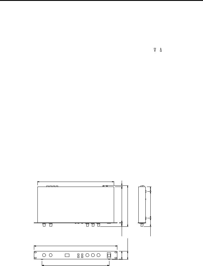
DIMENSIONS (W × H × D) |
480 mm × 45 mm × 232 mm |
WEIGHT |
2.5 kg |
ACCESSORY |
AC Adapter |
*Dynamic range is measured with a 6 dB/octave LPF at 12.7 kHz — equivalent to a 20 kHz LPF with infinite dB/octave attenuation.
*0 dB = 0.775V RMS
*Specifications and appearance are subject to change without notice.
Dimensions
440 |
|
|
7 |
|
|
|
|
26 |
203 |
D: 232 |
151.5 |
2.6 |
|
|
19.4 |
|
47.5 |
W:480 |
H:45 |
|
|
|
|
44 |
|
|
388 |
|
|
10

Français
APPAREIL DE RÉVERBÉRATION NUMÉRIQUE
MANUEL D’INSTRUCTIONS

Introduction
Le REV100 est un appareil de réverbération de qualité, abordable et simple à utiliser. Il vous rendra de grands services aussi bien dans votre studio personnel qu’avec un petit système d’amplification. Il s’agit s’un véritable processeur stéréo doté de deux e ntrées et deux sorties.
Outre une réverbération stéréo de haute qualité, le REV100 vous propose des effets de réverbération & delay ainsi que de modula - tion & réverbération. Le convertisseur 16 bits A/N et N/A offre une qualité de son exceptionnelle ainsi qu’une large réponse en fréquence grâce à la vitesse d’échantillonnage de 44,1kHz.
Le REV100 est un appareil facile à manier, pourvu de commandes rotatives pour régler les niveaux et éditer des paramètres. Une connexion MIDI IN est comprise de sorte que les programmes d’effet peuvent également être sélectionnés au moyen de messages MIDI.
Pour profiter au maximum des atouts que vous offre votre REV100, veuillez lire attentivement ce manuel et le ranger soigneusement afin de pouvoir le consulter ultérieurement.
Table des matières
1. Commandes . . . . . . . . . . . . . . . . . 1
Panneau avant . . . . . . . . . . . . . . . . . . . . . . . . . 1 Panneau arrière . . . . . . . . . . . . . . . . . . . . . . . . . 1
2. Fonctionnement . . . . . . . . . . . . . . 2
Installation et connexions . . . . . . . . . . . . . . . . 2 Changement de programmes . . . . . . . . . . . . . . 2
4. Mode MIDI . . . . . . . . . . . . . . . . . . 7
Tableau de changement de programme MIDI . 7 Réglage du tableau de changement de programme MIDI . . . . . . . . . . . . . . . . . . . . . . . . . . . . . . . . 7 Réglage du canal de réception MIDI . . . . . . . . 8 Contrô le des paramètres en temps réel . . . . . . 8 MIDI Data Format . . . . . . . . . . . . . . . . . . . . . . 9
3. Mode Edit . . . . . . . . . . . . . . . . . . . 6
Edition d’un programme . . . . . . . . . . . . . . . . . 6 Sauvegarde d’un programme . . . . . . . . . . . . . . 6 Initialisation du REV100 . . . . . . . . . . . . . . . . . 6
5. Fiche technique . . . . . . . . . . . . . . 10
Caractéristiques générales . . . . . . . . . . . . . . . 10 Dimensions . . . . . . . . . . . . . . . . . . . . . . . . . . 10
MIDI Implementation Chart
Précautions
1.Emplacement
Ne placez pas l’appareil dans un endroit où il risque d’être exposé à des températures élevées ou une forte humidité (évitez la proximité de radiateurs, poêles, etc). Evitez également les endroits poussiéreux ou soumis à des vibrations qui peuvent être à l’origine de dommages mécaniques ainsi que les endroits sujets à des champs magnétiques importants, tels que la proximité de matériel de transmission.
2.Evitez tout choc
Un choc relativement important peut endommager l’appareil. Maniez-le donc avec soin.
3.N’ouvrez pas le boîtier et n’essayez pas d’effectuer des réparations vous-même
Cet appareil ne contient pas d’élément pouvant être réparé par l’utilisateur. Veuillez donc confier toute réparation à un technicienYamaha qualifié. Toute tentative d’ouverture du boîtier et de manipulation des circuits internes se soldera par la perte du bénéfice de la garantie.
4.Coupez toujours l’alimentation avant de procéder à des branchements
N’oubliez jamais de mettre les appareils hors tension avant de brancher ou de débrancher des câbles afin de ne pas endommager l’appareil lui-même ainsi que le matériel qui y est branché.
5.Manipulez les câbles avec soin
Pour brancher et débrancher des câbles (y compris le câble d’alimentation), prenez-le toujours par la prise et non par le câble.
6.Nettoyez avec un chiffon doux et sec
N’utilisez jamais de solvants, tels que du benzène ou un diluant pour nettoyer l’appareil. Prenez les poussières avec un chiffon doux et sec.
7.Utilisez toujours une source d’alimentation adéquate
N’utilisez que l’adaptateur fourni parYamaha pour mettre l’appareil sous tension. Le recours à un autre adaptateur risque d’endommager sérieusement l’appareil. Ne branchez jamais l’appareil à un circuit de plusieurs appareils branchés en cascade.
 Loading...