


FCC INFORMATION (U.S.A.)
1.IMPORTANT NOTICE: DO NOT MODIFY THIS UNIT!
This product, when installed as indicated in the instructions contained in this manual, meets FCC requirements. Modifications not expressly approved by Yamaha may void your authority, granted by the FCC, to use the product.
2.IMPORTANT: When connecting this product to accessories and/or another product use only high quality shielded cables. Cable/s supplied with this product MUST be used. Follow all installation instructions. Failure to follow instructions could void your FCC authorization to use this product in the USA.
3.NOTE: This product has been tested and found to comply with the requirements listed in FCC Regulations, Part 15 for Class “B” digital devices. Compliance with these requirements provides a reasonable level of assurance that your use of this product in a residential environment will not result in harmful interference with other electronic devices. This equipment generates/uses radio frequencies and, if not installed and used according to the instructions found in the users manual, may cause interference harmful to the operation of other electronic devices. Compliance with FCC regulations does not guarantee that interference will not occur in all installations. If this product is found to be the source of interference, which can be determined by turning the unit “OFF” and “ON”, please try to eliminate the problem by using one of the following measures:
Relocate either this product or the device that is being affected by the interference.
Utilize power outlets that are on different branch (circuit breaker or fuse) circuits or install AC line filter/s.
In the case of radio or TV interference, relocate/reorient the antenna. If the antenna lead-in is 300 ohm ribbon lead, change the lead-in to co-axial type cable.
If these corrective measures do not produce satisfactory results, please contact the local retailer authorized to distribute this type of product. If you can not locate the appropriate retailer, please contact Yamaha Corporation of America, Electronic Service Division, 6600 Orangethorpe Ave, Buena Park, CA90620
*This applies only to products distributed by YAMAHA CORPORATION OF AMERICA.
ADVARSEL!
Lithiumbatteri Eksplosionsfare ved fejlagtig håndtering. Udskiftning må kun ske med batteri af samme fabrikat og type. Levér det brugte batteri tilbage til leverandoren.
VARNING
Explosionsfara vid felaktigt batteribyte. Använd samma batterityp eller en ekvivalent typ som rekommenderas av apparattillverkaren. Kassera använt batteri enlight fabrikantens instruktion.
VAROITUS
Paristo voi räjähtää, jos se on virheellisesti asennettu.
Vaihda paristo ainoastaan laitevalmistajan suosittelemaan tyyppiin. Hävitä käytetty paristo valmistajan ohjeiden mukaisesti.
NEDERLAND / THE NETHERLANDS
•Dit apparaat bevat een lithium batterij voor geheugen back-up.
•This apparatus contains a lithium battery for memory back-up.
•Raadpleeg uw leverancier over de verwijdering van de batterij op het moment dat u het apparaat ann het einde van de levensduur afdankt of de volgende Yamaha Service Afdeiing:
Yamaha Music Nederland Service Afdeiing Kanaalweg 18-G, 3526 KL UTRECHT
Tel. 030-2828425
•For the removal of the battery at the moment of the disposal at the end of the service life please consult your retailer or Yamaha Service Center as follows:
Yamaha Music Nederland Service Center
Address: Kanaalweg 18-G, 3526 KL UTRECHT
Tel : 030-2828425
•Gooi de batterij niet weg, maar lever hem in als KCA.
•Do not throw away the battery. Instead, hand it in as small chemical waste.

SPECIAL MESSAGE SECTION
This product utilizes batteries or an external power supply (adapter). DO NOT connect this product to any power supply or adapter other than one described in the manual, on the name plate, or specifically recommended by Yamaha.
WARNING: Do not place this product in a position where anyone could walk on, trip over ,or roll anything over power or connecting cords of any kind. The use of an extension cord is not recommended! IF you must use an extension cord, the minimum wire size for a 25' cord (or less ) is 18 AWG. NOTE: The smaller the AWG number ,the larger the current handling capacity. For longer extension cords, consult a local electrician.
This product should be used only with the components supplied or; a cart, rack, or stand that is recommended by Yamaha. If a cart, etc., is used, please observe all safety markings and instructions that accompany the accessory product.
SPECIFICATIONS SUBJECT TO CHANGE:
The information contained in this manual is believed to be correct at the time of printing. However, Yamaha reserves the right to change or modify any of the specifications without notice or obligation to update existing units.
This product, either alone or in combination with an amplifier and headphones or speaker/s, may be capable of producing sound levels that could cause permanent hearing loss. DO NOT operate for long periods of time at a high volume level or at a level that is uncomfortable. If you experience any hearing loss or ringing in the ears, you should consult an audiologist.
IMPORTANT: The louder the sound, the shorter the time period before damage occurs.
Some Yamaha products may have benches and / or accessory mounting fixtures that are either supplied with the product or as optional accessories. Some of these items are designed to be dealer assembled or installed. Please make sure that benches are stable and any optional fixtures (where applicable) are well secured BEFORE using.
Benches supplied by Yamaha are designed for seating only. No other uses are recommended.
NOTICE:
Service charges incurred due to a lack of knowledge relating to how a function or effect works (when the unit is operating as designed) are not covered by the manufacturer’s warranty, and are therefore the owners responsibility. Please study this manual carefully and consult your dealer before requesting service.
ENVIRONMENTAL ISSUES:
Yamaha strives to produce products that are both user safe and environmentally friendly. We sincerely believe that our products and the production methods used to produce them, meet these goals. In keeping with both the letter and the spirit of the law, we want you to be aware of the following:
Battery Notice:
This product MAY contain a small non-rechargeable battery which (if applicable) is soldered in place. The average life span of this type of battery is approximately five years. When replacement becomes necessary, contact a qualified service representative to perform the replacement.
This product may also use “household” type batteries. Some of these may be rechargeable. Make sure that the battery being charged is a rechargeable type and that the charger is intended for the battery being charged.
When installing batteries, do not mix batteries with new, or with batteries of a different type. Batteries MUST be installed correctly. Mismatches or incorrect installation may result in overheating and battery case rupture.
Warning:
Do not attempt to disassemble, or incinerate any battery. Keep all batteries away from children. Dispose of used batteries promptly and as regulated by the laws in your area. Note: Check with any retailer of household type batteries in your area for battery disposal information.
Disposal Notice:
Should this product become damaged beyond repair, or for some reason its useful life is considered to be at an end, please observe all local, state, and federal regulations that relate to the disposal of products that contain lead, batteries, plastics, etc. If your dealer is unable to assist you, please contact Yamaha directly.
NAME PLATE LOCATION:
The name plate is located on the bottom of the product. The model number, serial number, power requirements, etc., are located on this plate. You should record the model number, serial number, and the date of purchase in the spaces provided below and retain this manual as a permanent record of your purchase.
Model
Serial No.
Purchase Date
PLEASE KEEP THIS MANUAL
92-BP

PRECAUTIONS
PLEASE READ CAREFULLY BEFORE PROCEEDING
* Please keep these precautions in a safe place for future reference.
 WARNING
Always follow the basic precautions listed below to avoid the possibility of serious injury or even death from electrical shock, short-circuiting, damages, fire or other hazards. These precautions include, but are not limited to, the following:
•Do not open the instrument or attempt to disassemble the internal parts or modify them in any way. The instrument contains no user-serviceable parts. If it should appear to be malfunctioning, discontinue use immediately and have it inspected by qualified Yamaha service personnel.
•Do not expose the instrument to rain, use it near water or in damp or wet conditions, or place containers on it containing liquids which might spill into any openings.
•If the AC adaptor cord or plug becomes frayed or damaged, or if there is a sudden loss of sound during use of the instrument, or if any unusual smells or smoke should appear to be caused by it, immediately turn off the power switch, disconnect the adaptor plug from the outlet, and have the instrument inspected by qualified Yamaha service personnel.
•Use the specified adaptor (PA-5C or an equivalent recommended by Yamaha) only. Using the wrong adaptor can result in damage to the instrument or overheating.
•Before cleaning the instrument, always remove the electric plug from the outlet. Never insert or remove an electric plug with wet hands.
•Check the electric plug periodically and remove any dirt or dust which may have accumulated on it.
 CAUTION
Always follow the basic precautions listed below to avoid the possibility of physical injury to you or others, or damage to the instrument or other property. These precautions include, but are not limited to, the following:
•Do not place the AC adaptor cord near heat sources such as heaters or radiators, and do not excessively bend or otherwise damage the cord, place heavy objects on it, or place it in a position where anyone could walk on, trip over, or roll anything over it.
•When removing the electric plug from the instrument or an outlet, always hold the plug itself and not the cord.
•Do not connect the instrument to an electrical outlet using a multipleconnector. Doing so can result in lower sound quality, or possibly cause overheating in the outlet.
•Unplug the AC power adaptor when not using the instrument, or during electrical storms.
•Before connecting the instrument to other electronic components, turn off the power for all components. Before turning the power on or off for all components, set all volume levels to minimum.
•Do not expose the instrument to excessive dust or vibrations, or extreme cold or heat (such as in direct sunlight, near a heater, or in a car during the day) to prevent the possibility of panel disfiguration or damage to the internal components.
•Do not use the instrument near other electrical products such as televisions, radios, or speakers, since this might cause interference which can affect proper operation of the other products.
•Do not place the instrument in an unstable position where it might accidentally fall over.
•Before moving the instrument, remove all connected adaptor and other cables.
•When cleaning the instrument, use a soft, dry cloth. Do not use paint thinners, solvents, cleaning fluids, or chemical-impregnated wiping cloths. Also, do not place vinyl, plastic or rubber objects on the instrument, since this might discolor the panel or keyboard.
•Do not rest your weight on, or place heavy objects on the instrument, and do not use excessive force on the buttons, switches or connectors.
•Do not operate the instrument for a long period of time at a high or uncomfortable volume level, since this can cause permanent hearing loss. If you experience any hearing loss or ringing in the ears, consult a physician.
■REPLACING THE BACKUP BATTERY
•This instrument contains a non rechargeable internal backup battery which permits internal data to remain stored even when the power is off. When the backup battery needs replacing, the message "Backup Battery Low" will display in the display. When this happens, immediately back up your data, then have qualified Yamaha service personnel replace the backup battery.
•Do not attempt to replace the backup battery yourself, in order to prevent the possible serious hazards. Always have qualified Yamaha service personnel replace the backup battery.
•Never place the backup battery in a location that a child can reach, since a child might accidentally swallow the battery. If this should happen, consult a physician immediately.
■SAVING USER DATA
•Always save data to a floppy disk frequently, in order to help prevent the loss of important data due to a malfunction or user operating error.
Yamaha cannot be held responsible for damage caused by improper use or modifications to the instrument, or data that is lost or destroyed.
Always turn the power off when the instrument is not in use.
(3)-3

How to use the manuals/Printing conventions in this manual
Owner’s Manual
Introduction
Thank you for choosing a Yamaha RM1x Sequence Remixer.
The RM1x is a complete dance-music workstation that can be used both as a real-time performance instrument and a powerful production tool. Its intuitive interface makes real-time operation easy for artists with a DJ background, while in-depth sequencing and editing functions make it possible to create sophisticated original patterns and songs from scratch. In addition to powerful sequence recording and playback capability, the RM1x also features a great sounding tone generator built in — so you don’t need any extra equipment. You can even edit the voices to create sounds that are perfectly suited to your music.
Keep this Owner’s Manual handy while familiarizing yourself with the RM1x, and store it in a safe place for later reference.
5

Main Features
Main Features
•The sequencer of the RM1x provides 16 sequence tracks and up to 110,000 notes of storage capacity for professional-level sequencing power. Note timing resolution is 1/480th of a quarter note. Memory is backed up, so your data will not disappear when the power is turned off.
•Easy operation with the large 64 x 240 dot display.
•Intuitive performance control with 8 assignable real-time control knobs, 4 display knobs, and a large multi-function keyboard.
•An awesome assortment of preset patterns means you can play right away without having to program.
•Easy programming via an advanced interface that allows a wide range of parameters to be accessed and edited — when you need to be in total control of your sound.
•Powerful sequencing capabilities with in-depth editing function make it possible to create even complex patterns and musical textures.
•Assemble grooves in real time in the Pattern mode: each of the Pattern mode’s “styles” has up to 16 “sections” which can be directly switched in real time during playback via the RM1x keyboard.
•Advanced tone generator technology gives you a extensive arsenal of outstanding sounds built in.
•Edit and refine the RM1x voices to create sounds that most ideally suit your own music.
•A sophisticated multi-effect system can be used to add anything from subtle ambiance to wild variations.
•Tap BPM entry lets you define tempos the way you feel them rather than with numbers.
•Full MIDI compatibility means that the RM1x can be used as the core of a larger music production system.
6 RM1x SEQUENCE REMIXER

How to use the manuals/Printing conventions in this manual
How to use the manuals
The documentation for the RM1x consists of the following two manuals. Understand the role of each manual, and refer to them as necessary.
Owner's Manual (this manual)
This explains precautions for use, how to make connections, and all parameters and commands. Use this manual like a dictionary whenever you need to.
Chapter 1. Basic concepts
Chapter 2. Pattern mode
Chapter 3. Pattern Chain mode
Chapter 4. Song mode
Chapter 5. Utility mode
“Pattern mode”, “Pattern chain mode” and “Song mode” have several functions in common.
In this manual, explanations for these common functions are given in greater detail in chapter 2 “Pattern mode”. Some of the overlapping explanation in chapter 3 “Pattern Chain mode” and chapter 4 “Song mode” is omitted. In such cases, the appropriate page of chapter 2 “Pattern mode” is indicated so that you can refer to it.
List Book
This is a booklet that contains various lists such as the Voice list, Preset Style list, Effect list, MIDI data format, and MIDI implementation chart.
Printing conventions in this manual
This manual uses the following icons to indicate buttons and to distinguish different types of information.
pThis indicates a panel button. The symbol in the box indicates the symbol printed on the button.
12 This indicates the actual procedure for using the function.
nThis indicates supplementary explanations related to the function, examples of use, and hints.
RM1x SEQUENCE REMIXER 7

Finding the information that you need
Finding the information that you need
In order to find the information that you need, you can make use of the following pages.
Table of contents (page 9)
Locate the desired information within the flow of the entire manual.
Front and rear panels (page 11)
Here you can read about the name and location of each button and control, and read about their function.
Quickstart Guide (page20)
This brief, easy-to-follow section shows you how to use the basic features and functions of your new RM1x.
Function tree (page 32)
This lets you locate the desired information within the structure of the command hierarchy.
Glossary (page 146)
This section contains unfamiliar terms or phrases in alphabetical order with their explanations.
Index (page 150)
This lets you search alphabetically for unfamiliar terms to find pages on which they are discussed and pages on which related topics appear.
8 RM1x SEQUENCE REMIXER

Table of Contents |
|
|
SETUP |
|
|
1. |
Front and rear panels .................................................................................................................................................................. |
11 |
|
Front Panel .......................................................................................................................................................... |
11 |
|
Rear Panel ........................................................................................................................................................... |
14 |
|
Floppy disk drive ................................................................................................................................................ |
15 |
2. |
Connections |
|
|
Power supply connections .................................................................................................................................. |
16 |
|
Audio equipment connections ............................................................................................................................ |
17 |
|
Connecting a footswitch ..................................................................................................................................... |
18 |
|
Connecting external MIDI devices ..................................................................................................................... |
18 |
|
Connecting a MTR (multi-track recorder) .......................................................................................................... |
19 |
3. |
Quickstart Guide ........................................................................................................................................................................ |
20 |
4. |
Using the included disk .............................................................................................................................................................. |
22 |
BASIC OPERATION ......................................................................................................................................................... |
23 |
|
Chapter 1. BASIC CONCEPTS |
|
|
1. |
Function tree ............................................................................................................................................................................... |
32 |
2. |
How the RM1x is organized ....................................................................................................................................................... |
34 |
3. |
Sequencer block ......................................................................................................................................................................... |
35 |
4. |
Tone generator block .................................................................................................................................................................. |
37 |
5. |
Controller block .......................................................................................................................................................................... |
38 |
6. |
Effect block ................................................................................................................................................................................ |
39 |
7. About floppy disks ...................................................................................................................................................................... |
42 |
|
Chapter 2. PATTERN MODE |
|
|
1. PATTERN Playback ................................................................................................................................................................... |
46 |
|
2. |
Recording ................................................................................................................................................................................... |
49 |
3. |
Groove ........................................................................................................................................................................................ |
55 |
4. |
Play FX ....................................................................................................................................................................................... |
57 |
5. |
MIDI delay ................................................................................................................................................................................. |
60 |
6. Arpeggio ..................................................................................................................................................................................... |
62 |
|
7. Voice ........................................................................................................................................................................................... |
63 |
|
8. Voice Edit ................................................................................................................................................................................... |
65 |
|
9. |
Effect .......................................................................................................................................................................................... |
69 |
10. Setup ......................................................................................................................................................................................... |
73 |
|
11. Disk .......................................................................................................................................................................................... |
76 |
|
12. Job ............................................................................................................................................................................................ |
80 |
|
13. Edit ........................................................................................................................................................................................... |
99 |
|
14. Split ........................................................................................................................................................................................ |
108 |
|
Chapter 3. PATTERN CHAIN MODE |
|
|
1. |
Pattern Chain Playback ............................................................................................................................................................ |
110 |
2. |
Disk .......................................................................................................................................................................................... |
111 |
3. |
Job ............................................................................................................................................................................................ |
112 |
Chapter 4. SONG MODE |
|
|
1. SONG Playback ....................................................................................................................................................................... |
116 |
|
2. |
Recording ................................................................................................................................................................................. |
117 |
3. |
Groove ...................................................................................................................................................................................... |
119 |
4. |
Play FX ..................................................................................................................................................................................... |
119 |
5. |
MIDI delay ............................................................................................................................................................................... |
119 |
6. Arpeggio ................................................................................................................................................................................... |
119 |
|
7. Voice ......................................................................................................................................................................................... |
120 |
|
8. Voice Edit ................................................................................................................................................................................. |
120 |
|
RM1x SEQUENCE REMIXER 9

Table of Contents
9. Effect ........................................................................................................................................................................................ |
120 |
|
10. |
Setup ....................................................................................................................................................................................... |
121 |
11. |
Disk ........................................................................................................................................................................................ |
122 |
12. |
Job .......................................................................................................................................................................................... |
123 |
13. |
Edit ......................................................................................................................................................................................... |
128 |
14. |
Split (Song to Pattern) ............................................................................................................................................................ |
129 |
Chapter 5. UTILITY MODE
1. |
System ...................................................................................................................................................................................... |
132 |
2. |
MIDI Setup ............................................................................................................................................................................... |
135 |
3. |
MIDI Filter ............................................................................................................................................................................... |
137 |
Appendix
1. |
Specifications ........................................................................................................................................................................... |
140 |
2. Troubleshooting ........................................................................................................................................................................ |
142 |
|
3. |
Error Messages ......................................................................................................................................................................... |
144 |
4. |
Glossary .................................................................................................................................................................................... |
146 |
5. |
Index ......................................................................................................................................................................................... |
150 |
The illustrations and LCD screens as shown in this owner’s manual are for instructional purposes only, and may be different from the ones on your RM1x.
10 RM1x SEQUENCE REMIXER
SETUP
SETUP
1. Front and rear panels
Front Panel
2 |
3 |
|
|
16 |
7 |
1 |
|
|
|
|
|
|
4 |
|
|
|
11 |
6 |
5 |
12 |
10 |
|
|
13 |
|
|
|
|
|
|
9 |
9 |
17 |
18 |
8 |
16 |
15 |
|
|
14 |
19 |
1. BPM Display
Normally this 4-digit LED numeric display shows the current BPM (Beats Per Minute) value, right down to a tenth of a beat. It can be switched to display measure numbers rather than beats per minute via a utility function (page 133). The BPM display also shows values related to the real time Controller Knobs (page 12), but only while any of the knobs are operated.
2. MIDI Data Monitors
The MIDI IN and OUT indicators above the BPM display light whenever MIDI data is received via the rear-panel MIDI IN connector (red MIDI IN indicator), or when MIDI data is transmitted by the RM1x via the MIDI OUT connector (green MIDI OUT indicator).
3. LCD Display
The RM1x's large backlit LCD display panel displays the parameters and values related to the currently selected operation or mode. The Display Knobs (page 12) and Function Buttons located immediately below the LCD display directly affect the corresponding parameters or functions on the display. The [DISPLAY] and [CURSOR] buttons are also closely related to display operation, and details are provided in the “Basic Operation” section beginning on page 23.
A CONTRAST control for the LCD display is provided on the rear panel (page 14). The LCD display can be set for normal or inverse (white on black) display via a utility mode function (page 133).
RM1x SEQUENCE REMIXER 11

SETUP
4. Display Knobs
The four knobs located immediately below the LCD display directly control the corresponding parameters on the display. For example, in the main PATTERN mode Display Knob 1 can be used to select a style, and Display Knob 4 can be used to set the BPM. More details are provided in the “Basic Operation” section beginning on page 23.
5. Function Buttons and Indicators
The function buttons - [F1] through [F4] - are similar to the Display Knobs in that they directly control the corresponding functions on the LCD display, but only when the related indicator is lit. More details are provided in the “Basic Operation” section beginning on page 23.
6. VOLUME Control
Adjusts the volume of the RM1x audio output via the rear-panel OUTPUT and PHONES jacks.
7. Real Time Controller Knobs & [KNOB] Button
These knobs allow the corresponding parameters to be controlled in real time during pattern or song playback. The parameters listed on the panel below the knobs are the default pre-assigned parameters, but other parameters can be assigned as required via the SETUP submode KNOB ASSIGN function (page 74). The knobs can be switched to control one of two different parameter groups - “A” and “B” - via the [KNOB] button. The “A” parameter group (the upper default parameters listed on the panel) are selected when the [KNOB] indicator is lit, and the “B” group (the lower parameters) is selected when the [KNOB] indicator is out. Different parameters can be assigned to both the “A” and “B” groups via the KNOB ASSIGN function mentioned above.
8. Cursor Buttons
The cursor buttons move the “cursor” around the LCD display screen, highlighting the various parameters that are available for editing (the RM1x cursor appears as a dark block with inverse characters).
9. [NO -1] and [YES +1] Buttons
The [NO -1] and [YES +1] buttons are used to edit (change the value of) the parameter at which the cursor is currently located. The [NO -1] button decrements (decreases stepwise) the value of the selected parameter, while the [YES +1] button increments (increases stepwise) the parameter. Press either button briefly to decrement or increment the parameter by one, or hold the button for continuous decrementing of incrementing in the specified direction.
The [NO -1] and [YES +1] button are also used to respond to certain prompts when they appear. Press [YES +1] to go ahead with the operation, or [NO -1] to cancel.
10. DISPLAY [<-] and [->] Buttons
When the selected mode or submode (page 23) includes more parameters than can fit on the display at one time, arrow symbols will appear at the left and/or right side of the display to indicate that more parameters are available in the indicated direction(s). The DISPLAY [<-] and [->] buttons can be used to scroll the display in the corresponding direction when this occurs.
11. MODE and SUBMODE Buttons
The four MODE buttons select the main RM1x operating modes (PATTERN, PATTERN CHAIN, SONG, and UTILITY), while the SUBMODE buttons select a range of submodes via which you can access the RM1x's detailed programming features. Details on mode and submode selection are provided in the “Basic Operation” section beginning on page 23.
12 RM1x SEQUENCE REMIXER

SETUP
12. [EXIT] Button
The [EXIT] button takes you out of any function selected by the function buttons, or the edit or job modes (described below), directly back to the current main mode (e.g. SONG or PATTERN).
13. Sequencer Buttons and Indicators
The sequencer buttons control recording and playback in the PATTERN, PATTERN CHAIN, and SONG modes.
REC |
Activates the record-ready mode in the RM1x PATTERN and SONG modes. The red REC |
e |
button indicator will light, then recording will begin as soon as the p button is pressed. |
|
The e button can be pressed again to cancel the record-ready mode before recording |
|
is actually started by pressing the p button. |
PLAY |
Starts playback from the current point in the pattern or song if the record-ready mode is |
p |
not active, or recording from the same point if the record-ready mode is active. The green |
|
PLAY indicator flashes at the current BPM during recording and playback. |
STOP |
Stops playback or recording. |
s |
|
|
|
r & f |
Fast reverse and forward. Press the r or f button to rapidly move through the pattern |
|
or song in the corresponding direction. |
t |
Top. Instantly returns to the first beginning of the current song or pattern (i.e. the first beat |
|
of the first measure). |
14. Keyboard
This 26-note keyboard makes it possible to program the RM1x without having to connect an external MIDI keyboard. It's even polyphonic, so you can directly enter chords as well as single notes. The only thing it lacks is velocity sensitivity. The RM1x does, however, accept velocity information from an external MIDI keyboard.
The keyboard also performs a range of functions as specified by the keyboard mode button (below): track selection, transposition, numeric data entry, track mute/solo, and section selection. The “black keys” also perform a range of other functions, such as selecting specific track ranges and memorizing a number of track mute setups.
15. Keyboard Mode Buttons
These buttons modify the function of the RM1x keyboard for track selection, transposition, numeric data entry, track mute/ solo, and section selection. Details are provided in the “Basic Operation” section beginning on page 23.
16. [OCT DOWN] and [OCT UP] Buttons
Although the range of the RM1x keyboard is a little over two octaves, the [OCT DOWN] and [OCT UP] buttons allow the pitch of the keyboard to be shifted down or up in octave steps, over a range of 8 (+/- 4) octaves. Each time the [OCT DOWN] button is pressed the pitch of the keyboard is shifted down by one octave, until the lower limit is reached. The [OCT UP] button shifts the pitch of the keyboard up in the same way. The current amount of octave shift is indicated on the LCD display.
17. [SHIFT] Button
The [SHIFT] button is used to access several secondary or “background” functions that you might only need in special situations. For example, the [SHIFT] button can be used when you want to “solo” a track instead of muting it via the [MUTE] keyboard mode button.
The [SHIFT] button can also be used in conjunction with the Display Knobs: hold the [SHIFT] button while rotating a knob for faster data selection.
18. [ARPEGGIO ON] Button
Turns the RM1x's automatic arpeggio feature on or off (page 62). The [ARPEGGIO ON] button indicator will light when the ARPEGGIO feature is on.
19. [TAP/ENTER] Button
This dual-purpose button is used both for tap-entry of BPM values (page 20), and to enter numeric values (page 26).
RM1x SEQUENCE REMIXER 13
SETUP
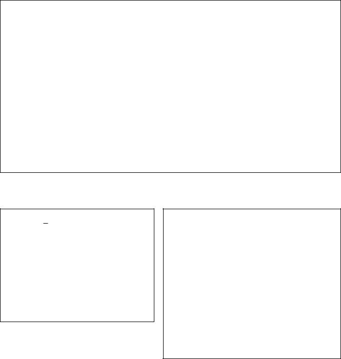
Rear Panel
4 |
3 |
7 |
5 |
6 |
2 |
1 |
1. STANDBY/ON Switch
Press in to turn the RM1x on, and press again to turn it off. When the power is on one of the mode button indicators will light and the PATTERN mode display will appear on the LCD (Liquid Crystal Display).
2. DC IN Jack
The DC output cable from the Yamaha PA-5C AC Power Adaptor supplied with the RM1x is plugged in here.
3. CONTRAST Control
Use the CONTRAST control to achieve the best LCD display visibility (LCD visibility varies greatly with viewing angle).
4. MIDI IN & OUT Connectors
The RM1x has MIDI IN and MIDI OUT connectors for maximum system flexibility. If you plan to use a MIDI keyboard or other instrument to play and program the RM1x, it should be connected to the RM1x MIDI IN connector (see “Connecting external MIDI devices,” page 18). Input “filters” defining what data will and will not be received by the MIDI IN connector can be set as required via the UTILITY mode (page 137).
The MIDI OUT connector can be connected to an external tone generator or synthesizer if you want to drive external voices from the RM1x sequencer. Like the MIDI IN connector, MIDI filters can be set for the MIDI OUT connector via the UTILITY mode.
5. L/MONO & R OUTPUT Jacks
These are the main stereo outputs from the RM1x tone generator system (see “Audio equipment connections,” page 17). Both are standard 1/4” mono phone plugs. When a plug is inserted into only the L/MONO output, the leftand rightchannels signals are mixed and delivered via that output to allow direct connection to mono sound systems. The output level is adjusted via the VOLUME control (page 12).
6. PHONES Jack
Any pair of stereo headphones with a 1/4” stereo phone plug can be plugged in here for convenient monitoring. The PHONES output level is adjusted via the VOLUME control.
7. FOOT SW Jack
An optional Yamaha FC4 or FC5 footswitch connected to this jack can be used for start/stop, section selection, sustain, or tap BPM entry, as determined by the setting of the UTILITY mode FOOT SWITCH parameter (page 132).
14 RM1x SEQUENCE REMIXER
SETUP
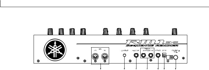
Floppy disk drive
1. Floppy disk slot
This is where floppy disks are inserted for loading or saving data. 3.5 inch 2HD (MF2HD) or 2DD (MF2DD) floppy disks can be used. (page 42)
2. Disk-in-use indicator
This indicator will light while data is being read from or written to the floppy disk. Never attempt to remove the disk while this indicator is lit.
3. Eject button
Press this button to remove the floppy disk. Disks must be inserted or removed gently and firmly, and only while the access indicator is dark.
|
|
|
|
|
|
|
|
|
|
2. Disk-in-use |
|
|
||
3. Eject button |
||||
indicator |
||||
|
|
|||
|
|
|
||
1. Floppy disk slot |
||||
nThe back of a floppy disk contains a write protect tab as shown in the following illustration. When this tab is in the downward position (with the window open), it will not be possible to modify, add, or delete data. When you wish to protect important data, you should leave the tab in this position.
Write permit
Write prohibit
Write protect tab
CAUTION !
Be aware that Yamaha can make no guarantee regarding data damage that results from improper use.
RM1x SEQUENCE REMIXER 15

SETUP
2. Connections
In order to use the RM1x, the included AC adaptor and an amp system etc. must be connected. If you use external MIDI devices or controllers, these must also be connected.
This sections explains how to make these connections.
CAUTION!
Be sure to turn off the STANDBY/ON switch before making any connections. If you make connections while the STANDBY/ON switch is on, you risk damaging external equipment such as the amp or speakers.
Power supply connections
1 Make sure that the STANDBY/ON switch of the RM1x is set to STANDBY, and connect the included AC adaptor (PA-5C) to the power supply jack.
Wrap the DC output cable of the adaptor around the cable clip (as shown below) to prevent accidental unplugging of the cable during operation.
2Plug the AC adaptor into an AC outlet, and turn on the RM1x STANDBY/ON switch.
When turning the power off, simply reverse the procedure.
WARNING!
Use only the included PA-5C AC adaptor (or other adaptor specifically recommended by Yamaha). Using other AC adaptors will cause malfunctions. Also, be sure to unplug the AC adaptor from the AC outlet if you will not be using the RM1x.
CAUTION!
Even when the switch is in the “STANDBY” position, electricity is still flowing to the instrument at the minimum level. When you are not using the RM1x for a long time, make sure you unplug the AC power adaptor from the wall AC outlet.
Never interrupt the power supply (e.g. unplug the AC adaptor) during any RM1x record operation! Doing so can result in a loss of data.
16 RM1x SEQUENCE REMIXER
SETUP
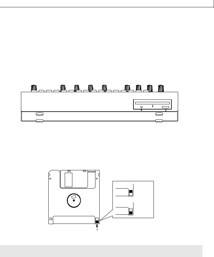
Audio equipment connections
To output the sound of the RM1x, connect an amp or mixer to the output jacks.
Connection to powered speakers
Connect two powered speakers (left and right) to the output jacks (L/MONO, R). If you are connecting only one powered speaker, use the L/MONO jack.
VOL
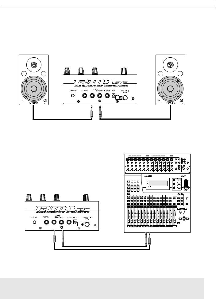
Connection to a mixer
Connect the output jacks (L/MONO, R) to two channels of the mixer. The channel connected to the L/MONO jack should be panned left, and the channel connected to the R jack should be panned right. Make the same type of connections if you are connecting the RM1x to an MTR or cassette deck.
|
|
|
|
|
PHANTOM +48V OFF ON |
|
|
|
|
|
PHANTOM +48V OFF ON |
|
|
|
|
|
|||
|
|
|
|
|
|
|
|
INPUT (BAL) |
|
|
|
|
|
|
|
|
|
||
|
|
|
|
|
|
|
|
|
|
|
|
|
|
|
13 |
15 |
–10dBV (UNBAL) |
||
|
|
|
|
|
|
|
|
|
|
|
|
|
|
|
L |
|
|
||
|
|
|
|
|
|
|
|
|
|
|
|
|
|
|
14 |
16 |
R |
|
|
|
|
|
|
|
|
|
|
|
|
|
|
|
|
|
|
|
|
||
|
|
|
|
|
|
|
|
|
|
|
|
|
|
|
|
|
IN |
OUT |
|
|
|
|
|
|
|
|
|
|
|
|
|
|
|
|
|
|
|
2TR |
PHONES |
|
|
|
|
|
|
|
|
|
|
|
|
|
|
|
|
|
|
|
|
PAD |
|
|
|
|
|
|
|
|
|
|
|
|
|
|
|
|
|
|
|
26dB |
26dB |
26dB |
|
26dB |
|
26dB |
26dB |
26dB |
|
26dB |
26dB |
26dB |
26dB |
26dB |
|
15/16 |
MONITOR |
|
|
|
|
|
|
|
|
|
|
|
|
|
|
|
|
|
|
2TR IN |
2TR IN |
|
|
GAIN |
GAIN |
GAIN |
|
GAIN |
|
GAIN |
GAIN |
GAIN |
|
GAIN |
GAIN |
GAIN |
GAIN |
GAIN |
GAIN |
GAIN |
|
LEVEL |
LEVEL |
1 |
2 |
3 |
|
4 |
|
5 |
6 |
7 |
|
8 |
9 |
10 |
11 |
12 |
13/14 |
15/16 |
MONITOR |
|
|
|
|
|
|
OUT |
PHONES |
||||||||||||||
|
|
|
|
|
|
|
|
|
|
|
|
|
|
DIGITAL MIXING CONSOLE |
|
|
|
||
|
|
|
|
|
|
|
|
|
|
|
|
|
|
|
EQ |
HIGH |
|
L STEREO R |
|
UTILITY |
MIDI |
SETUP |
|
VIEW |
|
|
|
|
|
|
|
|
|
|
PAN |
|
|
|
|
|
|
|
|
|
|
FUNCTION |
|
|
|
|
|
|
PAN |
|
|
HI-MID |
|
|
|
DYNAMICS |
EQ/ATT |
Ø/DELAY |
|
PAN/ |
|
|
|
|
|
|
|
|
F |
|
F |
|
|
|
|
ROUTING |
|
MEMORY |
|
|
|
|
|
|
G |
|
|
LO-MID |
|
|
|
||||
|
|
|
|
|
|
|
|
|
|
|
|
|
|
|
|
|
|
||
|
FADER MODE |
|
|
|
|
|
|
|
|
|
|
|
|
G |
LOW |
|
|
|
|
EFFECT 1 |
EFFECT 2 |
OPTION I/O |
REMOTE |
|
|
1 RETURN 2 |
|
|
|
|
|
|
|
|
|
|
|||
AUX 1 |
AUX 2 |
AUX 3 |
|
AUX 4 |
|
|
|
|
|
|
|
|
|
|
SELECTED CHANNEL |
|
|
|
|
HOME |
|
|
|
|
|
|
|
|
|
|
|
|
|
|
|
|
|
|
|
1 |
2 |
3 |
|
4 |
5 |
6 |
7 |
8 |
9 |
10 |
11 |
12 |
13/14 |
15/16 |
STEREO |
1 RETURN 2 |
|
|
|
17 |
18 |
19 |
|
20 |
21 |
22 |
23 |
24 |
|
|
|
|
|
|
MASTER |
|
|
|
|
SEL |
SEL |
SEL |
|
SEL |
SEL |
SEL |
SEL |
SEL |
SEL |
SEL |
SEL |
SEL |
SEL |
SEL |
SEL |
SEL |
SEL |
|
SOLO |
SOLO |
SOLO |
SOLO |
|
SOLO |
SOLO |
SOLO |
SOLO |
SOLO |
SOLO |
SOLO |
SOLO |
SOLO |
SOLO |
SOLO |
|
SOLO |
SOLO |
|
|
ON |
ON |
ON |
|
ON |
ON |
ON |
ON |
ON |
ON |
ON |
ON |
ON |
ON |
ON |
ON |
ON |
ON |
|
MEMORY |
|
|
|
|
|
|
|
|
|
|
|
|
|
|
|
–1/DEC |
|
+1/INC |
||
|
|
|
|
|
|
|
|
|
|
|
|
|
|
|
|
PARAMETER |
|
||
6 |
6 |
6 |
6 |
6 |
|
6 |
6 |
6 |
6 |
6 |
6 |
6 |
6 |
6 |
0 |
|
|
|
|
|
|
|
|
|
|
|
|
|
|
|
|
|
|
|
–5 |
|
|
|
|
0 |
0 |
0 |
0 |
0 |
|
0 |
0 |
0 |
0 |
0 |
0 |
0 |
0 |
0 |
–10 |
|
|
|
|
5 |
5 |
5 |
5 |
5 |
|
5 |
5 |
5 |
5 |
5 |
5 |
5 |
5 |
5 |
–15 |
|
|
|
|
|
–20 |
|
|
|
CURSOR |
||||||||||||||
10 |
10 |
10 |
10 |
10 |
|
10 |
10 |
10 |
10 |
10 |
10 |
10 |
10 |
10 |
|
|
|
|
|
|
–30 |
|
|
|
|
||||||||||||||
20 |
20 |
20 |
20 |
20 |
|
20 |
20 |
20 |
20 |
20 |
20 |
20 |
20 |
20 |
–40 |
|
|
|
|
40 |
40 |
40 |
40 |
40 |
|
40 |
40 |
40 |
40 |
40 |
40 |
40 |
40 |
40 |
–50 |
|
|
|
|
60 |
60 |
60 |
60 |
60 |
|
60 |
60 |
60 |
60 |
60 |
60 |
60 |
60 |
60 |
–70 |
|
|
|
|
|
|
|
|
|
|
|
|
|
|
|
|
|
|
|
– |
|
|
|
|
|
|
|
|
|
|
|
|
|
|
|
|
|
|
|
ENTER |
|
|
|
|
1 |
2 |
3 |
|
4 |
5 |
6 |
7 |
8 |
9 |
10 |
11 |
12 |
13/14 |
15/16 |
STEREO |
|
|
|
|
17 |
18 |
19 |
|
20 |
21 |
22 |
23 |
24 |
|
|
|
|
|
|
MASTER |
|
|
|
|
Using headphones
If you are using headphones, connect them to the rear panel PHONES (headphones) jack.
When using headphones, adjust the volume to an appropriate level that will not harm your hearing.
CAUTION !
Do not connect the output jacks of the RM1x to the mic input jacks of an amp or cassette deck etc. If they are connected to mic inputs, the sound quality may be impaired, and the device may be damaged. Also, when connecting the RM1x to a mixer or similar device, set the mixer channels to the Line Input position.
RM1x SEQUENCE REMIXER 17

SETUP
Connecting a footswitch
When using a separately sold FC4 or FC5 foot switch, insert the foot switch plug into the FOOT SW jack located on the rear panel.
FC4 or FC5
Connecting external MIDI devices
Connecting a MIDI keyboard
Realtime recording input will be easier if you use a MIDI keyboard.
Use a MIDI cable to connect the MIDI OUT of the external MIDI keyboard to the MIDI IN connector on the rear panel.
MIDI
OUT
Connecting a tone generator module
RM1x song and pattern playback data can be used to play an external tone generator module.
Use a MIDI cable to connect the MIDI OUT connector on the rear panel to the MIDI IN connector of the external MIDI device.
MIDI IN 

18 RM1x SEQUENCE REMIXER
SETUP
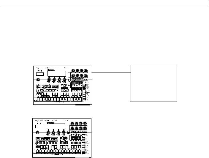
Connecting a MTR (multi-track recorder)
Since the RM1x implements MTC (MIDI Time Code) and MMC (MIDI Machine Control), you can produce music while synchronized to a MTCor MMC-compatible multi-track recorder.
Use MIDI cables to connect the MIDI OUT connector of the RM1x to the MIDI IN connector of the MTR, and the MIDI IN connector of the RM1x to the MIDI OUT connector of the MTR.
If you use MTC or MMC to control an MTR, set the Utility mode MIDI page MIDI Sync setting to “MTC."
Synchronizing the RM1x by MTC from an external device
MIDI OUT
MIDI IN
MTR (MTC,MMC-compatible)
Controlling an external device via MMC from the RM1x
|
MTR |
MIDI OUT |
(MTC,MMC-compatible) |
|
|
|
MIDI IN |
|
|
RM1x SEQUENCE REMIXER 19
SETUP
3. Quickstart Guide
When your RM1x is properly connected and powered up, try the following to get a feel for how easy it is to remix the preset patterns to create your own groove.
But remember, this is just the tipof the iceberg! The RM1x can do much, much more.
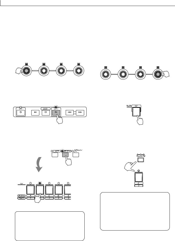
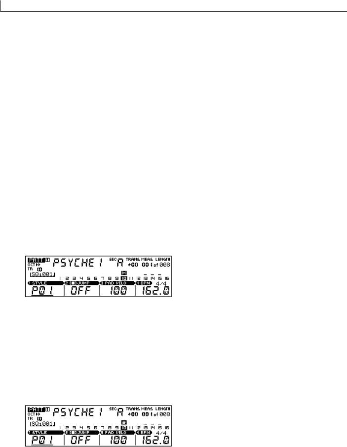
1. Select a Style
Use Display Knob 1 to select a preset style (P01 … P60).
2. Start Playback
Press the PLAY p button. The currently selected section of the selected style will begin playing. This “pattern” will continue to loop until a different section or style is selected.
3. Switch Sections
Make sure that the [SECTION] button indicator is flashing (if it isn’t, press the [SECTION] button so that it does), then use the white keys on the RM1x keyboard to switch sections.
4. Dial In a New BPM (Beat Per Minute)
Use Display Knob 4 to adjust the BPM to a value that feels right to you.
5. Tap In a New BPM
Tap on the [TAP] button a few times at the desired BPM. The RM1x will automatically adjust to the BPM you tap.
6. Transpose
Transpose the pattern to any key by pressing a key on the RM1x keyboard while holding the [TRANSPOSE] button.
A newly selected section will begin immediately. The current section is indicated by a flashing indicator above the corresponding key, and a letter (“A” … “P”) next to “SEC” in the display.
• More on section on page 28.
The central E key on the keyboard (labeled “H” and “8”) corresponds to no transposition. Higher or lower keys indicate transposition by the corresponding number of semitones in the corresponding direction. The amount of transposition is also indicated by the TRANS parameter in the display.
• More on transposition on page 27.
20 RM1x SEQUENCE REMIXER
SETUP
7. Use the Real-time Controller Knobs
Try rotating the RM1x controller knobs to hear their effect. The default parameters are labeled below each knob. The [KNOB] button selects the “A” or “B” parameter group.
When the mute mode is engaged the indicators above tracks which contain data will light. Press a key once to mute a track which contains data (its indicator will flash and “M” will appear above the tracks number in the display). Press the key again to un-mute a muted track.
• More on the Mute and Solo functions on page 28.
The knobs affect the currently selected track. You can quickly select any of the 16 tracks by pressing the appropriate white key on the RM1x keyboard (“1” … “16”) while holding the [TRACK] button. The number of the selected track will be highlighted in the display.
• More on track selection on page 27.
9. Play an Arpeggio
Press the [ARPEGGIO] button so that its indicator lights, then play an interval or chord on the RM1x keyboard. The RM1x will automatically create an arpeggio based on the notes you play.
The “A” parameter group (the upper default parameters listed on the panel) are selected when the [KNOB] indicator is lit, and the “B” group (the lower parameters) is selected when the [KNOB] indicator is out.
• More on the controller knobs on page 29.
Using the Arpeggio submode parameters you can select several different types of arpeggio.
• More on the Arpeggio mode on page 62.
8. Mute & Un-mute Tracks
Press the [MUTE] button so that its indicator flashes, then use the white keys on the RM1x keyboard to mute and unmute tracks as required.
10. Experiment With Different Styles
Use control knob 1 to select different styles and experiment with the various sections each contains.
Press the STOP s button to stop playback when done.
RM1x SEQUENCE REMIXER 21

SETUP
4. Using the included disk
Here's how to use the included disk.
Contents of the disk
The included disk contains 3 demo songs.
The demo songs allow you to enjoy demo playback, and to playback songs while adjusting the assignable knobs (PLAY FX and VOICE) to experience the possibilities of the RM1x.
Listening to the demo playback
Here's how to load a demo song file from disk and enjoy the demo playback.
1With the label facing upward, insert the disk into the floppy disk slot.
Insert the disk all the way until it clicks into place.
2Press the [SONG] button.
You will enter Song mode.
3Press the [DISK] button.
You will enter Disk submode.
4Press the [DISK] button again.
You will enter Load page, and the top line of the display will indicate “SONG DISK 2 Load”.
5Use the CURSOR button to move the cursor to the file you wish to play.
6Press the F1 button (LOAD!) to start the load operation.
The display will indicate “Executing...".
7Press the [SONG] button.
The top line of the display will indicate the loaded song name.
8 Press the PLAY p button to start playback.
9 Press the STOP s button to stop playback.
nBy changing the DISK FILE in step 5 you can playback other songs.
22 RM1x SEQUENCE REMIXER

Basic Operation
Basic Operation
1. Selecting Modes & Submodes
The RM1x has three main playback and recording modes — PATTERN, PATTERN CHAIN, and SONG — and a UTILITY mode. Each of these includes a range of “submodes” which provide access to more in-depth parameters.
Note that a number of dots appears to the left of the MODE and SUBMODE buttons. The number of dots beside each button indicates the number of display pages which can be accessed by that button. A button which has only one dot will access only a single page. A button which has 3 dots, for example, will access three different display pages in sequence. You can go back up through a sequence of pages from any page in the list by pressing the [EXIT] button the requisite number of times. The titles of the pages accessed by all multi-page MODE and SUBMODE buttons are listed on the top panel to the right of the buttons themselves. For example, looking at this list we can see that the SUBMODE [EFFECT] button, which has four dots, accesses the “Type” “Variation Edit” “Chorus Edit” and “Reverb Edit” pages.
The Main Modes
The main modes are directly accessed by pressing the corresponding MODE button: [PATTERN], [PATT CHAIN], [SONG], or [UTILITY]. The corresponding indicator will light, and the name of the selected mode will appear in the upper left-hand corner of the LCD Display. Here’s a brief summary of what the modes do, and page references to the related sections in this manual.
Mode |
Description |
Page |
PATTERN |
This is the RM1x mode you’ll probably use for most recording and playback operations, and is the |
|
|
default mode which will appear when the power is initially turned on. The [PATTERN] button alter- |
|
|
nately selects the main PATTERN mode and the PATCH mode in which phrases can be “patched” |
45 |
|
together to create patterns. |
|
|
|
|
|
In the RM1x the term “pattern” refers to a relatively short pattern - say, 4 to 16 measures - which is |
|
|
used for looped playback. |
|
|
|
|
PATTERN CHAIN |
The PATTERN CHAIN mode allows patterns to be “chained” together for automatic sequential |
109 |
|
playback. |
|
|
|
|
|
|
|
SONG |
Although you’ll probably use the PATTERN mode for most recording and playback operations, the |
|
|
RM1x SONG can be used to record and play complete songs when, for example, you want to |
115 |
|
create a continuous sequence of more than 256 measures, or use an odd time signature. |
|
|
|
|
UTILITY |
As its name implies, the UTILITY mode provides access to a range of utility functions which affect |
131 |
|
overall system and MIDI operation. |
|
|
|
RM1x SEQUENCE REMIXER 23

Basic Operation
The Submodes
The submodes are accessed via the SUBMODE buttons below the MODE buttons. When a SUBMODE button is pressed, the submode corresponding to the currently selected main MODE is selected. For example, the PATTERN mode JOB submode will be slightly different from the SONG mode JOB submode. The chart below includes brief summaries of what the submodes do, and page references to the related sections in this manual.
Mode |
Description |
Page |
GROOVE |
This submode makes it possible to adjust the pitch, timing, length, and velocity of notes via a 16th- |
55, 119 |
|
note grid to create “grooves” that would not be possible with precise sequencer-like programming. |
|
|
|
|
PLAY FX |
A range of play effects which affect the sound only during playback, without actually changing the |
|
|
sequence data. Play effects include harmonize, beat stretch, clock shift, gate time, and velocity |
57, 119 |
|
offset. |
|
MIDI DELAY |
MIDI Delay creates delay effects that can sound much the same as those created by conventional |
|
|
delay effect units, but the delays are created by manipulating the MIDI note data rather than the |
60, 119 |
|
audio signal. |
|
ARPEGGIO |
This feature can be used to create simple automatic arpeggios based on notes played on the |
62, 119 |
|
RM1x keyboard. |
|
|
|
|
VOICE |
The VOICE submode allows any of the RM1x’s voices to be assigned to individual tracks, and |
63, 120 |
|
includes volume, pan, and effect send controls for each track. |
|
|
|
|
VOICE EDIT |
This submode provides access to in-depth voice editing parameters that you can use to customize |
65, 120 |
|
voices for your own sound. |
|
|
|
|
EFFECT |
Detailed effect editing to add the finishing touches to your sound. |
69, 120 |
SETUP |
The SETUP submode includes a LOW BOOST function, knob assignment for the RM1x’s real- |
|
|
time control knobs, and individual output channel assignments for the internal tone generator and |
73, 121 |
|
MIDI transmission. |
|
DISK |
All disk operations can be accessed via this submode: save, load, file name, delete, rename, |
76, 111, 122 |
|
format, etc. |
|
|
|
|
JOB |
Accesses the RM1x’s extensive range of PATTERN, PATTERN CHAIN, and SONG jobs. |
80, 123 |
EDIT |
The EDIT submode allows detailed editing of sequence data, so you have complete control over |
99, 128 |
|
the pitch, timing, velocity, duration, and other parameters for each note. |
|
|
|
|
SPLIT |
The PATTERN SPLIT submode lets you copy specified measures from one section to another |
|
|
section. The SONG SPLIT submode is similar, but it lets you copy specified measures from a song |
108, 129 |
|
to a specified section. |
|
24 RM1x SEQUENCE REMIXER
Basic Operation
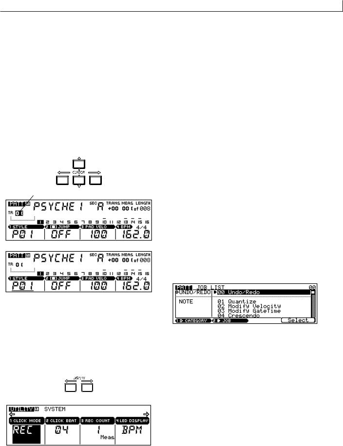
2. Navigating Around the Display
In all of the RM1x displays, the currently selected parameter or function is indicated by a “cursor” which can be either an inverse block (i.e. the selected value will appear as white characters in a black block, or the opposite if the “NEGA” mode is selected via the UTILITY mode LCD MODE function — page 133), or an underline. The underline type cursor is often used for parameters which are accessible via the display knobs (see below). The cursor can be moved around the display via the CURSOR buttons. Each of these four buttons moves the cursor in the direction indicated by the corresponding arrow (if the cursor can be moved in that direction). If you’re lost in a display and can’t locate cursor, try pressing the CURSOR buttons: you’ll spot the cursor as soon as it moves.
Cursor
 Cursor
If a selected mode has more parameters than can fit in a single display screen, an arrow will appear on one or both sides of the display, indicating that more parameters are available by scrolling in the corresponding direction(s). This can be accomplished either by moving the cursor past the end of the display by using the CURSOR buttons, or the display can scrolled directly by using the DISPLAY buttons.
Menu Selection
In JOB submodes (pages 80, 112, 123) you will be presented with a “menu” from which you can select a job. There are several ways to do this, as listed below:
CURSOR buttons |
Use the CURSOR buttons to scroll to |
|
the desired job, then press the Select |
|
function button (F4, below “Select ” on |
|
the display. |
Display Knobs |
Use the knob below “JOB” on the dis- |
|
play to scroll through the job list, then |
|
press the Select function button (F4, |
|
below “Select ” on the display.You can |
|
also use the CATEGORY knob to |
|
switch between job categories (listed |
|
to the left of the jobs). |
[NO -1]/[YES +1] buttons |
Press the [NO -1] or [YES +1] once |
|
briefly to single-step through the |
|
menu in the corresponding direction, |
|
or hold the button for continuous |
|
scrolling. When the desired job has |
|
been highlighted, press the Select |
|
function button (F4, below “Select ” on |
|
the display. |
Numeric Selection |
Use the numeric entry method de- |
|
scribed below to enter the number of |
|
the desired job. The job number will |
|
flash in the upper right corner of the |
|
display. Then press the [ENTER] but- |
|
ton. |
RM1x SEQUENCE REMIXER 25
Basic Operation
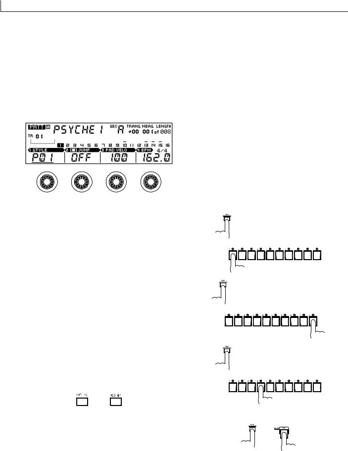
3. Changing (Editing) Values
The RM1x lets you adjust and edit values in three ways:
The Display Knobs
The display knobs provide a fast, easy way to adjust and edit corresponding parameters. If any parameters in the selected display can be accessed via the display knobs, they will appear directly above the knobs as shown in the example below.
To adjust a knob-related parameter, simply rotate the knob either clockwise to increase the value or counter-clockwise to decrease the value. For more rapid adjustment — when, for example, you need to quickly cover a large value range — rotate the appropriate display knob while holding the [SHIFT] button.
The function of the display knobs does not depend on cursor location, so you adjust the related values with the cursor located at another position on the display.
Numeric Entry
Numeric entry can be useful when you know precisely the value you want to enter, making it unnecessary to scroll through long lists of values or parameters to get the desired effect.
For numeric entry the cursor must be located at the value to be edited. Press and hold the [NUM] keyboard mode button
— the LEDs above the keys marked “1” through “9” and “0” will light, indicating that those keys can be used to enter a numeric value. While still holding the [NUM] button, press the number keys to enter the value, starting from the leftmost digit. To enter the value “104,” for example, press “1,” “0,” and then “4.” When the desired value has been specified, release the [NUM] button. The value should be flashing on the display as entered. Finally, press the [ENTER] button to actually enter the specified value.
The [NO -1] and [YES +1] But-
tons
The [NO -1] and [YES +1] buttons offer a convenient, precise way to increment or decrement the selected value in singlestep increments. After making sure that the cursor is located at the value to be edited, press either the [NO -1] or [YES +1] once briefly for a single step in the corresponding direction, or hold the button for continuous scrolling.
Note that the [NO -1] and [YES +1] buttons are also used to confirm or abort certain operations — thus the “NO” and “YES” labels.
n• For even faster decrementing or incrementing, press the
opposite increment/decrement button while holding the button corresponding to the direction you want to increment/decrement in.
26 RM1x SEQUENCE REMIXER
Basic Operation
4. The Function Buttons
The four function buttons below the LCD Display — F1 through F4 — only become active when necessary. When a function button is active, its indicator (the LED immediately to the left of the button) will light. The function buttons become active when a “go do it” type control is required. Disk “SAVE,” for example. Or the “DO!” function provided for most of the jobs.
5. Keyboard Modes
The RM1x keyboard does a lot more than simply enter notes. In conjunction with the KEYBOARD mode buttons it allows fast, efficient entry of a range of parameters. One of its alternative functions — numeric value entry — has already been discussed in the “Changing (Editing) Values” section, (page 26). The keyboard is also used for grid-type data entry in the Grid Groove (page 55) and Grid Step Record (page 54) modes. The remaining keyboard modes are summarized below:
(the corresponding indicator will flash and the selected track will be highlighted on the LCD Display), then release the [TRACK] button.
TRANSPOSE
This mode provides a fast, easy way to transpose playback pitch in semitone increments from -12 semitones to +13 semitones (used in conjunction with the OCTAVE buttons — page 13 — transposition is actually possible over a +/- 36 semitone range). When the [TRANSPOSE] button is held, the keyboard indicator(s) corresponding to the current transpose value will flash. A single flashing LED indicates the corresponding white key, and a pair of flashing LEDs indicates the black key between them.
The central E key on the keyboard (labeled “H” and “8”) corresponds to no transposition. Higher or lower keys indicate transposition by the corresponding number of semitones in the corresponding direction. The amount of transposition is also indicated by the TRANS parameter in the PATTERN and SONG displays.
To change the transpose value, simply press the appropriate key while holding the [TRANSPOSE] button.
TRACK
Allows direct track selection for recording and other trackdependent operations. To select one of the RM1x’s 16 tracks, press and hold the [TRACK] button. The indicator above the keyboard key corresponding to the currently selected track will flash. While still holding the [TRACK] button, simply press the key corresponding to the track you want to select
NUM
Described under “Numeric Entry” in the “Changing (Editing) Values” section (page 26).
RM1x SEQUENCE REMIXER 27
Basic Operation
MUTE (SOLO)
This button can be used in conjunction with the keyboard to mute or solo specific tracks. Tracks which are muted produce no sound during playback. If a track is soloed, only that track will be heard during playback.
To mute any number of tracks in the PATTERN or SONG mode, press the KEYBOARD [MUTE] button. The [MUTE] button indicator will flash. Next, press the keys corresponding to the tracks you want to mute — an “M” will appear above the track numbers of muted tracks on the LCD Display. Each time a key is pressed while the MUTE mode is engaged the corresponding track will be alternately muted and unmuted. You can then disengage the MUTE mode by pressing the [MUTE] button a second time (the [MUTE] button indicator will go out), and the current mute settings will remain in effect. Five separate mute setups can be memorized for instant recall as described in the “Mute Memory” section, below.
While the [MUTE] button indicator is flashing it is also possible to mute all tracks simultaneously by pressing the black key labeled [ALL]. In the same way tracks 1 through 8 can be muted at once by pressing the [1-8] key. In this case the remaining tracks (9 through 16) will all be un-muted. The [9- 16] key mutes tracks 9 through 16 while un-muting tracks 1 through 8. Pressing the next black key (C#) or the one next to that (BPM) will un-mute all muted tracks.
Only a single un-muted track can be soloed at a time, and unlike the mute settings, the solo function will be disengaged when the MUTE mode is disengaged. To solo a track, press the [MUTE] button while holding the [SHIFT] button. The [MUTE] button indicator will flash at a faster rate than when the MUTE mode is engaged, and the indicator above the currently soloed track will flash. Simply press a different key to solo a different track, then press the [MUTE] button a second time (the [MUTE] button indicator will go out) to disengage the SOLO mode.
Mute Memory
While the MUTE mode is engaged, the MUTE MEMORY buttons (the highest 5 black keys) can be used in conjunction with the [SHIFT] button to memorize the current mute setup: press a MUTE MEMORY button while holding the [SHIFT] button. Up to 5 different mute setups can be memorized in this way.
Memorized mute setups can be instantly recalled while the MUTE mode is engaged simply by pressing the appropriate MUTE MEMORY button.
SECTION
Styles in the RM1x PATTERN mode can have up to 16 “sections,” — “A” through “P.” Each section is effectively a separate pattern, and different sections can be used for introductions, variations, breaks, endings, etc. The SECTION mode allows the keyboard to be used for direct section selection, allowing you to quickly change sections during playback. When the KEYBOARD [SECTION] button is pressed the [SECTION] button indicator will flash, keyboard indicators corresponding to sections which contain data will light, and the keyboard indicator corresponding to the currently selected section will flash. The current section is also shown by the “SEC” parameter on the LCD Display. To select a different section, simply press the appropriate key. Press the [SECTION] button a second time to disengage the SECTION mode (the [SECTION] button indicator will go out).
28 RM1x SEQUENCE REMIXER
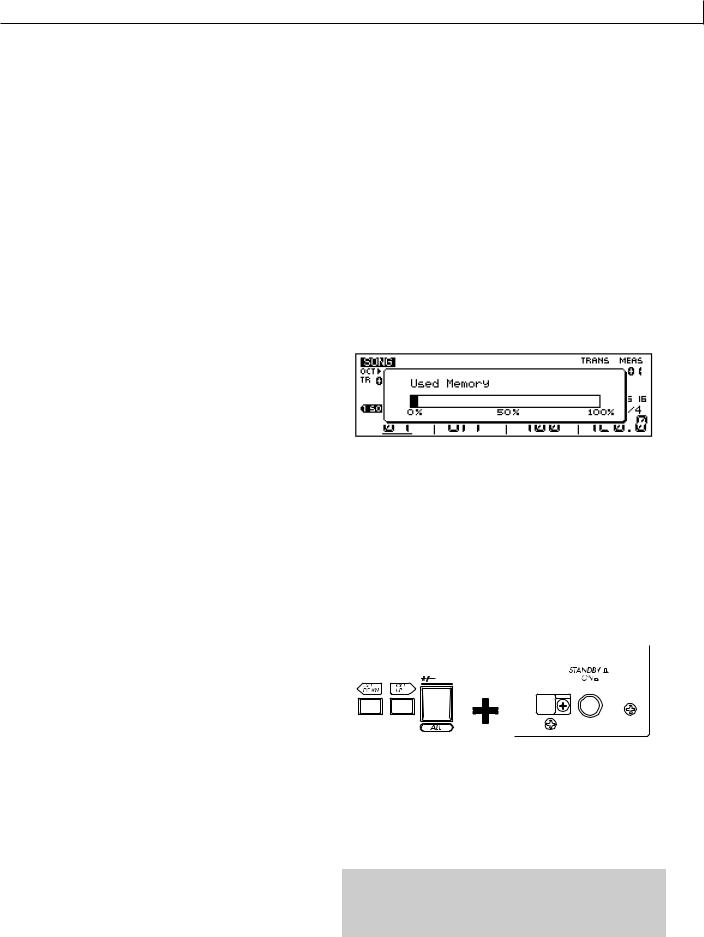
Basic Operation
6.The Realtime Controller Knobs
One of the features that makes the RM1x a great performance tool is its realtime controller knobs. The knobs allow the corresponding parameters to be controlled in real time during pattern or song playback, so, for example, you can sweep filter cutoff frequency, bend pitch, add or modify effects, or control just about any available parameter during playback simply by turning the appropriate knob. A complement of 8 controller knobs means you have instant access to multiple parameters, and you can control more than one parameter at the same time.
The parameters listed on the panel below the knobs are the default pre-assigned parameters, but other parameters can be assigned as required via the SETUP submode Knob Assign function (page 74). The knobs can be switched to control one of two different parameter groups - “A” and “B” - via the [KNOB] button. The “A” parameter group (the upper default parameters listed on the panel) are selected when the [KNOB] indicator is lit, and the “B” group (the lower parameters) is selected when the [KNOB] indicator is out. Different parameters can be assigned to both the “A” and “B” groups via the KNOB ASSIGN function mentioned above. The default “A” and “B” group parameters are listed below.
1 |
BEAT STRETCH |
MIDI DELAY |
2 |
CLOCK SHIFT |
OCTAVER |
3 |
GATE TIME |
HARMONIZE 1 |
4 |
VELOCITY |
HARMONIZE 2 |
5 |
CUTOFF |
VARIATION |
6 |
RESONANCE |
CHORUS |
7 |
EG DECAY |
REVERB |
8 |
PITCH BEND |
TRACK VOLUME |
n• This procedure does the same thing as the Undo/Redo job
in the Pattern job (page 82), Pattern chain job (page 113), and Song job (page 124).
8. Used Memory display
Here's how to check the amount of currently used memory, so that you can see about how much more recording can be done. Press the F1 button while holding the [SHIFT] button. The “Used Memory” will appear as long as you continue holding these buttons.
9. System Initialization
If you wish to reset the RM1x’s settings to the factory condition, you can perform the Initialization operation.
1While holding down the [OCT DOWN] and [OCT UP] buttons and the F#/Gb key [ALL] located at their right, turn on the STANDBY/ON switch.
7. Undo/Redo
Undo is a function that cancels the last-executed recording, edit, or job operation, and restores the data to its previous condition. Redo is a function that cancels the Undo operation, and re-executes the operation.
These jobs are very convenient when important data has been damaged because of recording, editing, or a job. These jobs can be used for recording, editing, and job (except Name) operations in the Pattern mode, Pattern chain mode, and the Song mode, and for Patch operations in the Pattern mode.
To execute the Undo operation, press the [JOB] button while holding the [SHIFT] button. To execute the Redo operation, press the [JOB] button while holding the [SHIFT] button again.
After a recording, editing, or job operation has been performed, it will always be possible to execute Undo. Likewise, it will always be possible to execute Redo after Undo has been executed, and Undo and Redo will alternate.
2 When “RM1x” appears in the display, release the keys.
3When initialization has been performed, “Factory Set” appears briefly in the display.
CAUTION!
When initialization is performed, all internal memory will be erased. If you wish to keep any of your data, you must save it to floppy disk before initializing.
RM1x SEQUENCE REMIXER 29

Basic Operation
Simultaneous Button & Knob Functions
|
|
This chart lists a number of RM1x functions which are |
|
|
|
accessed either by simultaneously pressing two buttons, or by |
|
|
|
operating a knob while holding a button. |
|
|
|
|
|
Buttons/knobs simultaneously operated |
Description |
See page |
|
SHIFT |
STOP |
Specifies the current measure as the measure the RM1x will “jump” to |
46 |
|
|
when the [STOP] button is pressed. |
|
SHIFT |
PLAY |
Starts loop playback of the currently selected song in the SONG mode. |
116 |
SHIFT |
MUTE |
Engages the SOLO mode. |
28 |
SHIFT |
PATTERN |
Resets parameter changes applied by the Knobs in the PATTERN mode. |
29 |
SHIFT |
PATT CHAIN |
Resets parameter changes applied by the Knobs in the PATT CHAIN |
29 |
|
|
mode. |
|
SHIFT |
SONG |
Resets parameter changes applied by the Knobs in the SONG mode. |
29 |
SHIFT |
GROOVE |
Resets the GROOVE parameters of the selected track. |
55, 119 |
SHIFT |
PLAY FX |
Resets the PLAY FX parameters of the selected track. |
57, 119 |
SHIFT |
MIDI DELAY |
Resets the MIDI DELAY parameters of the selected track. |
60, 119 |
SHIFT |
F1 |
Displays the amount of memory currently in use. |
29 |
SHIFT |
MUTE MEMORY |
Stores the MUTE MEMORY setting. |
28 |
SHIFT |
SECTION[A] - [P] |
Simultaneously hold the [SHIFT] button and the desired section button to |
28, 132 |
|
|
auto-retrigger section change according to the Pattern Quantize value |
|
|
|
(page 132). |
|
|
|
|
|
SHIFT |
Keyboard |
Adds the specified note during arpeggio playback. |
21, 62, 119 |
SHIFT |
Keyboard |
Deletes the specified note during PATTERN Realtime Recording. |
51 |
SHIFT |
Keyboard |
Deletes the specified note during Step Recording. |
52, 118 |
SHIFT |
Keyboard |
Selects the specified note during Grid Step Recording. |
53, 118 |
SHIFT |
Keyboard |
Selects a single note position and deselect all others in the GRID |
55, 119 |
|
|
GROOVE submode. |
|
SHIFT |
Display Knob1 - 4 |
Rotate the appropriate Display Knob while holding the [SHIFT] button for |
26 |
|
|
coarser, more rapid adjustment. |
|
SHIFT |
Knob 1 - 8 |
Allows the knob position to be changed without changing the effect |
29 |
|
|
parameter. |
|
|
|
|
|
SHIFT |
Knob 1 - 8 |
Deletes all corresponding parameter data during PATTERN realtime |
51 |
|
|
recording. |
|
|
|
|
|
SHIFT |
JOB |
Executes the Undo/Redo operation. |
29 |
TRACK |
TRACK[1] - [16] |
Selects the specified track. |
27 |
|
|
|
|
TRACK |
BPM |
Selects the BPM track in the SONG mode. |
116 |
TRACK |
OCT DOWN |
Moves the cursor to successively lower track numbers. |
25 |
|
|
|
|
TRACK |
OCT UP |
Moves the cursor to successively higher track numbers. |
25 |
|
|
|
|
TRACK |
CURSOR buttons |
Moves the cursor to tracks in the corresponding directions. |
25 |
TRACK |
ALL |
While holding the [TRACK] and [ALL] buttons simultaneously, the effect |
29 |
|
|
of the Knobs will be applied to all tracks. |
|
|
|
|
|
TRACK |
[1] - [8] |
While holding the [TRACK] and [1~8] buttons simultaneously, the effect |
29 |
|
|
of the Knobs will be applied to tracks 1~8. |
|
|
|
|
|
TRACK |
[9] - [16] |
While holding the [TRACK] and [9~16] buttons simultaneously, the effect |
29 |
|
|
of the Knobs will be applied to tracks 9~16. |
|
|
|
|
|
TRANSPOSE |
Keyboard |
Changes the transpose value. |
27 |
|
|
|
|
NUM |
NUM [1]-[9], [0] |
Enters the specified number. |
26 |
|
|
|
|
OCT UP |
OCT DOWN |
Resets the keyboard octave. |
13 |
|
|
|
|
OCT UP |
Keyboard |
Applies a maximum vibrato effect to the note. |
13 |
|
|
|
|
OCT DOWN |
Keyboard |
Bends the note up to the maximum pitch allowed by the currently |
13 |
|
|
specified pitch bend range. |
|
30 RM1x SEQUENCE REMIXER
 Loading...