


DVR-S150
DVD RECEIVER
DVR-S150
UB
OWNER’S MANUAL
IMPORTANT SAFETY INSTRUCTIONS
1 Read these instructions.
CAUTIO
N
RISK OF ELECTRIC SHOCK
DO NOT OPEN
CAUTION: TO REDUCE THE RISK OF
ELECTRIC SHOCK, DO NOT REMOVE
COVER (OR BACK). NO USER-SERVICEABLE
PARTS INSIDE. REFER SERVICING TO
QUALIFIED SERVICE PERSONNEL.
* Explanation of Graphical Symbols
The lightning flash with arrowhead
symbol, within an equilateral triangle,
is intended to alert you to the presence
of uninsulated “dangerous voltage”
within the product’s enclosure that may
be of sufficient magnitude to constitute
a risk of electric shock to persons.
The exclamation point within an
equilateral triangle is intended to alert
you to the presence of important
operating and maintenance (servicing)
instructions in the literature
accompanying the appliance.
IMPORTANT
Please record the serial number of this unit in the space
below.
MODEL:
Serial No.:
The serial number is located on the rear or the bottom of
this unit.
Retain this Owner’s Manual in a safe place for future
reference.
2 Keep these instructions.
3 Heed all warnings.
4 Follow all instructions.
5 Do not use this apparatus near water.
6 Clean only with dry cloth.
7 Do not block any ventilation openings. Install in
accordance with the manufacturer’s instructions.
8 Do not install near any heat sources such as radiators,
heat registers, stoves, or other apparatus (including
amplifiers) that produce heat.
9 Do not defeat the safety purpose of the polarized or
grounding-type plug. A polarized plug has two blades
with one wider than the other. A grounding type plug has
two blades and a third grounding prong. The wide
blade or the third prong are provided for your safety. If
the provided plug does not fit into your outlet, consult an
electrician for replacement of the obsolete outlet.
10 Protect the power cable from being walked on or pinched
particularly at plugs, convenience receptacles, and the
point where they exit from the apparatus.
11 Only use attachments/accessories specified by the
manufacturer.
12 Use only with the cart, stand, tripod,
bracket, or table specified by the
manufacturer, or sold with the
apparatus. When a cart is used, use
caution when moving the cart/
apparatus combination to avoid injury
from tip-over.
13 Unplug this apparatus during lightning storms or when
unused for long periods of time.
i CAUTION
14 Refer all servicing to qualified service personnel.
Servicing is required when the apparatus has been
damaged in any way, such as power-supply cord or plug
is damaged, liquid has been spilled or objects have fallen
into the apparatus, the apparatus has been exposed to
rain or moisture, does not operate normally, or has been
dropped.
15 Be sure to allow spaces of at least 10 cm above, behind
and on both sides of the DVR-S150.
16 Do not place the following objects on this unit:
A vessel with water in it.
If the vessel falls by vibrations and water spills, it may
cause damage to the unit, and/or you may get an electric
shock.

FCC INFORMATION (for US customers)
IMPORTANT SAFETY INSTRUCTIONS
1. IMPORTANT NOTICE : DO NOT MODIFY THIS
UNIT!
This product, when installed as indicated in the instructions
contained in this manual, meets FCC requirements.
Modifications not expressly approved by Yamaha may void
your authority, granted by the FCC, to use the product.
2. IMPORTANT :
When connecting this product to accessories and/or another
product use only high quality shielded cables. Cable/s
supplied with this product MUST be used. Follow all
installation instructions. Failure to follow instructions could
void your FCC authorization to use this product in the USA.
3. NOTE :
This product has been tested and found to comply with the
requirements listed in FCC Regulations, Part 15 for Class
“B” digital devices. Compliance with these requirements
provides a reasonable level of assurance that your use of this
product in a residential environment will not result in
harmful interference with other electronic devices.
This equipment generates/uses radio frequencies and, if not
installed and used according to the instructions found in the
users manual, may cause interference harmful to the
operation of other electronic devices.
Compliance with FCC regulations does not guarantee that
interference will not occur in all installations. If this product
is found to be the source of interference, which can be
determined by turning the unit “OFF” and “ON”, please try
to eliminate the problem by using one of the following
measures:
Relocate either this product or the device that is being
affected by the interference.
Utilize power outlets that are on different branch (circuit
breaker or fuse) circuits or install AC line filter/s.
In the case of radio or TV interference, relocate/reorient the
antenna. If the antenna lead-in is 300 ohm ribbon lead,
change the lead-in to coaxial type cable.
If these corrective measures do not produce satisfactory
results, please contact the local retailer authorized to
distribute this type of product. If you can not locate the
appropriate retailer, please contact Yamaha Electronics
Corp., U.S.A. 6660 Orangethorpe Ave, Buena Park, CA
90620.
The above statements apply ONLY to those products
distributed by Yamaha Corporation of America or its
subsidiaries.
We Want You Listening For A Lifetime
YAMAHA and the Electronic Industries Association’s Consumer
Electronics Group want you to get the most out of your equipment by playing it at a safe level. One that lets the sound come
through loud and clear without annoying blaring or distortion –
and, most importantly, without affecting your sensitive hearing.
Since hearing damage from loud sounds is often
undetectable until it is too late, YAMAHA and the
Electronic Industries Association’s Consumer
Electronics Group recommend you to avoid prolonged exposure from excessive volume levels.
CAUTION ii
CAUTION: READ THIS BEFORE OPERATING YOUR UNIT.
1 To assure the finest performance, please read this manual
carefully. Keep it in a safe place for future reference.
2 Install this sound system in a well ventilated, cool, dry, clean
place with at least 10 cm on the top, 10 cm on the left and right,
and 10 cm at the back of DVR-S150 — away from direct
sunlight, heat sources, vibration, dust, moisture, and/or cold.
3 Locate this unit away from other electrical appliances, motors, or
transformers to avoid humming sounds.
4 Do not expose this unit to sudden temperature changes from cold
to hot, and do not locate this unit in an environment with high
humidity (i.e. a room with a humidifier) to prevent condensation
inside this unit, which may cause an electrical shock, fire,
damage to this unit, and/or personal injury.
5 Avoid installing this unit where foreign object may fall onto this
unit and/or this unit may be exposed to liquid dripping or
splashing. On the top of this unit, do not place:
– Other components, as they may cause damage and/or
discoloration on the surface of this unit.
– Burning objects (i.e. candles), as they may cause fire, damage
to this unit, and/or personal injury.
– Containers with liquid in them, as they may fall and liquid
may cause electrical shock to the user and/or damage to this
unit.
6 Do not cover this unit with a newspaper, tablecloth, curtain, etc.
in order not to obstruct heat radiation. If the temperature inside
this unit rises, it may cause fire, damage to this unit, and/or
personal injury.
7 Do not plug in this unit to a wall outlet until all connections are
complete.
8 Do not operate this unit upside-down. It may overheat, possibly
causing damage.
9 Do not use force on switches, knobs and/or cords.
10 When disconnecting the power cable from the wall outlet, grasp
the plug; do not pull the cable.
11 Do not clean this unit with chemical solvents; this might damage
the finish. Use a clean, dry cloth.
12 Only voltage specified on this unit must be used. Using this unit
with a higher voltage than specified is dangerous and may cause
fire, damage to this unit, and/or personal injury. YAMAHA will
not be held responsible for any damage resulting from use of this
unit with a voltage other than specified.
13 To prevent damage by lightning, disconnect the power cable from
the wall outlet during an electrical storm.
14 Do not attempt to modify or fix this unit. Contact qualified
YAMAHA service personnel when any service is needed.
The cabinet should never be opened for any reasons.
15 When not planning to use this unit for long periods of time (i.e.
vacation), disconnect the AC power plug from the wall outlet.
16 Be sure to read the “Troubleshooting” section on common
operating errors before concluding that this unit is faulty.
17 Before moving this unit, press STANDBY/ON to set this unit in
standby mode, and disconnect the AC power plug from the wall
outlet.
18 Condensation will form when the surrounding temperature
changes suddenly. Disconnect the power cable from the outlet,
then leave the unit alone.
19 When using the unit for a long time, the unit may become warm.
Turn the power off, then leave the unit alone for cooling.
This unit is not disconnected from the AC power source as
long as it is connected to the wall outlet, even if this unit itself
is turned off. This state is called the standby mode. In this
state, this unit is designed to consume a very small quantity of
power.
FOR CANADIAN CUSTOMERS
To prevent electric shock, match wide blade of plug to wide
slot and fully insert.
This Class B digital apparatus complies with Canadian
ICES-003.
DANGER
When this unit is plugged to the wall outlet, do not place your
eyes close to the opening of the disc tray and other openings to
look into inside.
The laser component in this product is capable of emitting
radiation exceeding the limit for Class 1.
WARNING
TO REDUCE THE RISK OF FIRE OR ELECTRIC SHOCK,
DO NOT EXPOSE THIS APPLIANCE TO RAIN OR
MOISTURE.
■ For U.K. customers
If the socket outlets in the home are not suitable for the plug
supplied with this appliance, it should be cut off and an
appropriate 3 pin plug fitted. For details, refer to the instructions
described below.
Note
The plug severed from the mains lead must be destroyed, as a
plug with bared flexible cord is hazardous if engaged in a live
socket outlet.
■ Special Instructions for U.K. Model
IMPORTANT
THE WIRES IN MAINS LEAD ARE COLOURED IN
ACCORDANCE WITH THE FOLLOWING CODE:
Blue: NEUTRAL
Brown: LIVE
As the colours of the wires in the mains lead of this apparatus may not correspond with the coloured markings
identifying the terminals in your plug, proceed as follows:
The wire which is coloured BLUE must be connected to
the terminal which is marked with the letter N or coloured
BLACK. The wire which is coloured BROWN must be
connected to the terminal which is marked with the letter L
or coloured RED.
Making sure that neither core is connected to the earth
terminal of the three pin plug.
iii CAUTION
CAUTION: READ THIS BEFORE OPERATING YOUR UNIT.
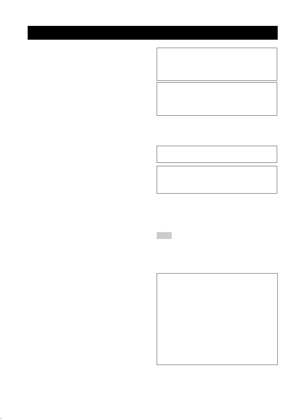
CAUTION
Use of controls or adjustments or performance of procedures
other than those specified herein may result in hazardous
radiation exposure.
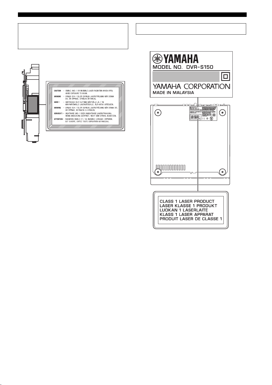
¶ The name plate is located on the bottom of the unit.
CAUTION iv

Contents
CONTENTS
INTRODUCTION
Introduction ............................................................ 3
About this manual...................................................... 3
Supplied Accessories .............................................. 3
Controls and Functions .......................................... 4
Top and front panels .................................................. 4
Display....................................................................... 5
Remote control........................................................... 6
PREPARATION
Connecting Speakers .............................................. 9
Connecting speakers
(Front/Surround/Center) ...................................... 10
Connecting a subwoofer .......................................... 10
Using commercially available speakers or cables ...11
Connecting a TV ................................................... 12
Connecting Antennas ........................................... 13
Connecting the FM antenna..................................... 13
Connecting the AM loop antenna ............................ 13
Connecting External AV Components ............... 14
Connecting a VCR................................................... 15
Connecting a game console ..................................... 16
Connecting a CD recorder or MD recorder ............. 17
Connecting the Power Cables.................................. 17
Installing Batteries in the Remote Control ........ 18
Using the Remote Control.................................... 18
BASIC OPERATION
Turning the Power to On/Standby...................... 19
Selecting an Input Source .................................... 19
Adjusting the Volume Level ................................ 20
Muting the Sound (Mute) .................................... 20
Auto Speaker Setup (YPAO) ............................... 21
Enjoying Sound Field Programs
(DSP Programs) ................................................ 26
Setting the Sleep Timer ........................................ 28
Changing DVD Settings on the TV
(On-Screen Menu) ............................................ 29
Operating the On-Screen Menu ............................... 29
On-Screen Menu guide ............................................ 30
ENJOYING MOVIE AND MUSIC DISCS
Supported Disc Types ...........................................32
Basic Playback Operations ...................................33
Useful Playback Operations .................................34
Specifying an elapsed time for playback (Time
Search)................................................................. 34
Customizing playback order (Program Play) .......... 35
Repeating playback (Repeat Play)........................... 37
Operating disc menus (DVD menu/Video CD
Playback Control)................................................ 39
Selecting Audio and Subtitle Languages ............40
Selecting a Viewing Angle ...................................41
Zooming Images ...................................................42
Restricting Playback (Parental Control) ...........43
Setting the Parental Control level............................ 43
Locking discs ........................................................... 44
Playing locked discs ................................................ 44
Changing the password............................................ 45
Enjoying High-Quality Video
(NTSC/Progressive Scan) ................................46
Enjoying JPEG Images .........................................47
ENJOYING RADIO
Tuning Radio Stations ..........................................48
Tuning radio stations automatically
(Auto Tuning)...................................................... 48
Tuning radio stations manually (Manual Tuning)... 48
Selecting preset radio stations (Preset Tuning) .......49
Receiving FM RDS stations
(U.K. and Europe models only)........................... 49
Presetting Radio Stations .....................................51
Presetting FM stations automatically
(Auto Preset)........................................................ 51
Presetting radio stations manually
(Manual Preset) ................................................... 52
Changing the order of preset radio stations ............. 52
ENJOYING EXTERNAL AV SOURCES
Playing Back External Sources............................53
TV playback ............................................................ 53
VCR playback.......................................................... 53
Game console playback ........................................... 54
Recording AV Sources With External AV
Components .......................................................55
Recording audio sources with CinemaStation......... 55
Copying video component sources to a video
cassette................................................................. 56
1

Contents
SOUND OPTIONS
Enjoying Sound with Specific Speakers.............. 57
Enjoying 6.1/5.1ch sources with all speakers
including a virtual speaker (Matrix 6.1) .............. 57
Enjoying 2ch sources with all speakers
(Dolby Pro Logic II)............................................ 58
Enjoying DSP programs with the front speakers
only (Virtual CINEMA DSP).............................. 59
Enjoying DSP Programs in a Variety of
Ways ................................................................... 60
Listening with headphones
(“SILENT CINEMA”) ........................................ 60
Listening at low volume
(Night Listening) ................................................. 61
Enjoying High-Quality Sound ............................. 62
Enjoying original Dolby and DTS sounds............... 62
Enjoying original 2ch sound (Stereo) ...................... 63
ADVANCED CONFIGURATION
Adjusting the Speaker Balance During
Playback.............................................................64
Adjusting the speaker balance with test tones ......... 64
Adjusting the speaker balance during playback ...... 65
Configuring Dolby Pro Logic II Music
Settings ............................................................... 67
DSP Program Delay Time Settings ..................... 68
Configuring the Audio Input Signal Setting.......70
Checking the Audio Input Signal Type ................... 71
Controlling External Components ...................... 72
Setting remote control codes ................................... 72
Available operations ................................................ 73
Configuring Various Parameters (Set Menu) ....75
Operating the Set Menu........................................... 76
APPENDIX
Troubleshooting .................................................... 80
General..................................................................... 80
Remote control ........................................................ 83
Disc playback .......................................................... 84
Radio reception........................................................ 85
Additional Information ........................................ 86
Disc Information...................................................... 86
Handling a disc ........................................................ 87
Glossary .................................................................88
Audio formats .......................................................... 88
Sound field programs............................................... 89
Audio information ................................................... 89
Video signal information ......................................... 90
Copyright and logo marks ....................................... 91
Specifications ......................................................... 92
2
Introduction
The YAMAHA CinemaStation “DVR-S150” is a slimline DVD receiver equipped with a digital amplifier. This product provides you
with the best sound possible, allowing you to enjoy not just DVDs and CDs, but various other AV sources as well. We hope the
“DVR-S150” brings you great listening pleasure and satisfaction.
About this manual
• This manual provides information relevant only to the YAMAHA CinemaStation “DVR-S150”. For information on speakers or other
AV equipment, refer to the manual for that product.
• In this manual, operations that can be performed using either the DVD receiver or its remote control are explained using the remote
control.
• Remote control descriptions and illustrations in this manual are based on the U.K. and Europe models unless otherwise specified.
• y indicates a tip for your operation.
• Notes contain important information about safety and operating instructions.
• This manual is printed prior to production. Design and specifications are subject to change in part as a result of improvements, etc. In
case of differences between the manual and the product, the product has priority.
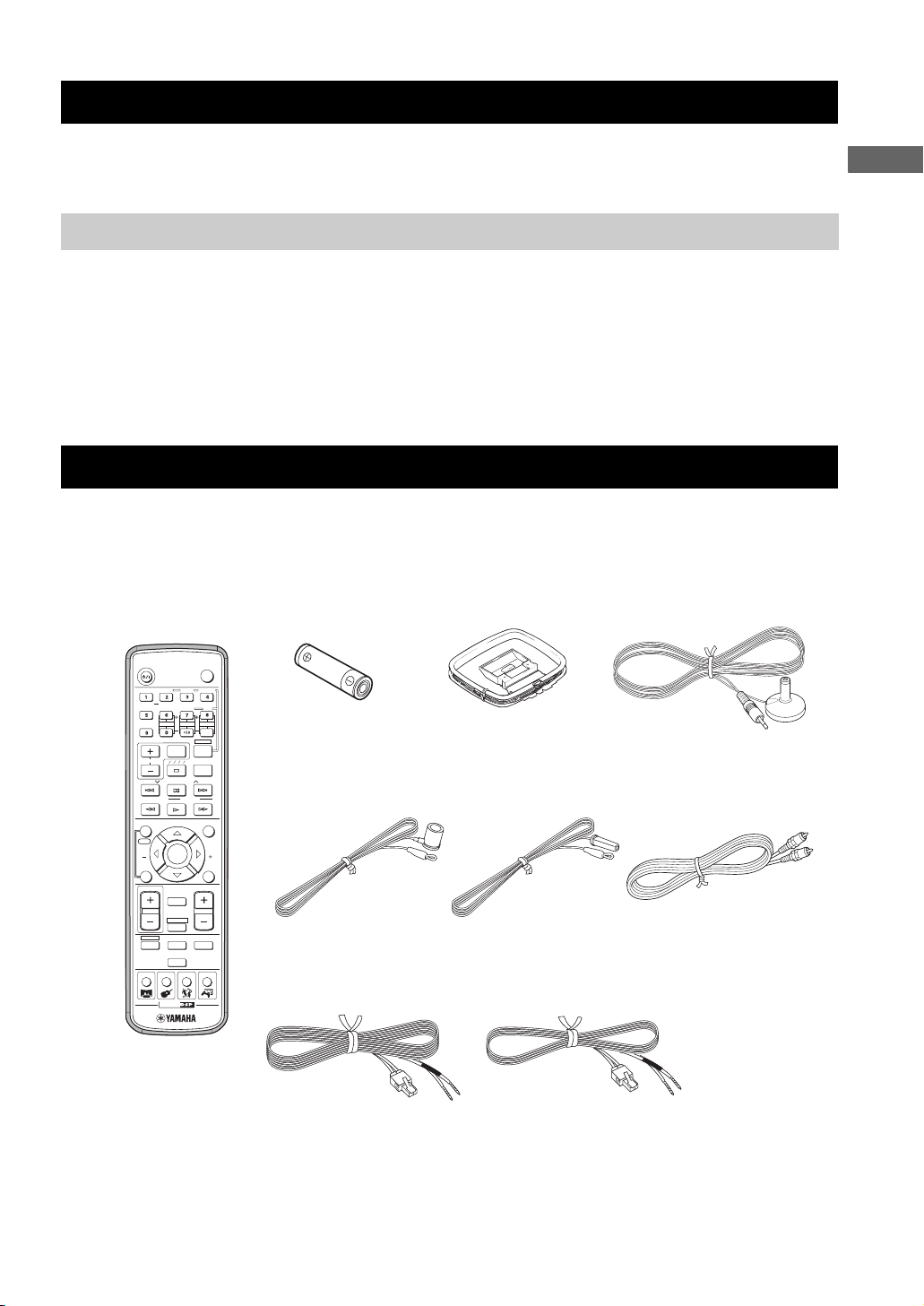
Supplied Accessories
This product includes the following accessories. Before connecting speakers or a TV to this product, make sure you received all of the
following parts.
INTRODUCTION
Remote
control
STANDBY/ON
AUDIO
ANGLE
SELECT
SURROUND
REPEAT
NIGHT
SW
CENTER
SET MENU
TV INPUT
TV CH
A B C D E
PRESET PRESET
PTY SEEK
MODE
FREQ/RDS
ON SCREEN
START
YPAO
CH
ENTER
STATUS
ON/OFF
TV VOL
MUTE
AMP
DVD/CD
VCR
TUNER
MOVIE MUSIC SPORTS GAME
CINEMA
TEST
POWER
SUBTITLE
SHIFT
SLEEP
VOLUME
VIDEO
(AA, R06, UM-3)
Optimizer microphoneAM loop antennaBatteries (2)
TV
STEREOMATRIX 6.1
A-B
SURR
Indoor FM antenna
(U.S.A., Canada, China,
START
MENU
CH
RETURN
Asia and General
models)
(Europe, U.K.,
Australia and Korea
models)
Video pin
cable
Speaker cables
Surround
15m (2)
Front, Center
5m (3)
3
CONTROLS AND FUNCTIONS
Controls and Functions
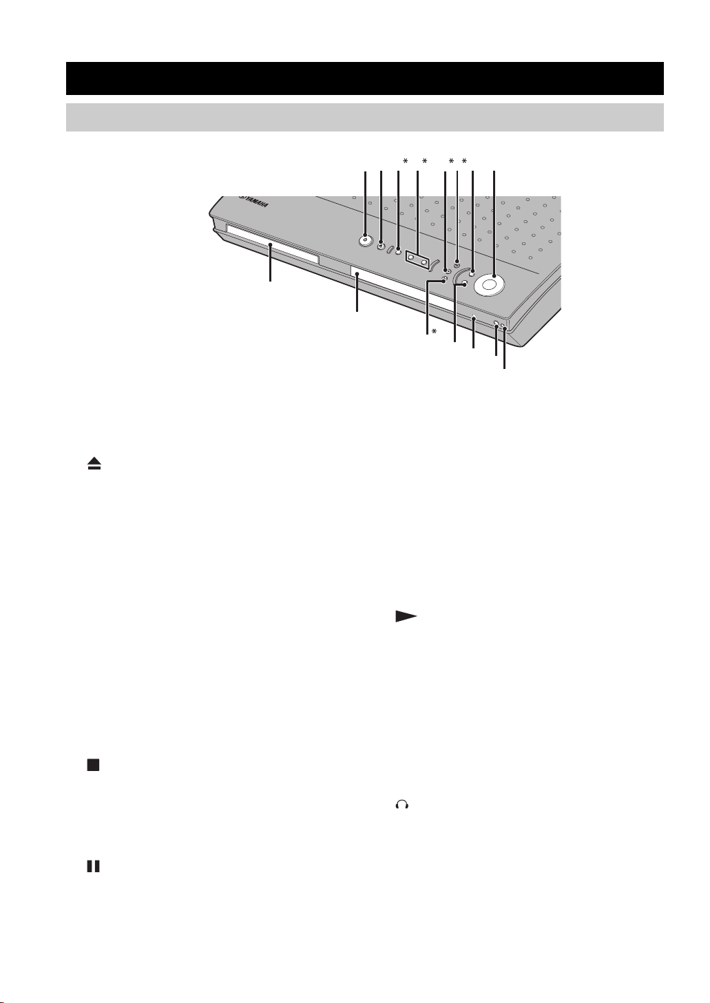
Top and front panels
Buttons indicated with an asterisk (*) perform different functions depending on the selected mode of operation.
B
7
C
8
D
E
12 3 4 56
9
0
A
1 STANDBY/ON
Turn this unit on. Press to set the unit in the standby mode.
(page 19)
2
Opens and closes the disc tray.
3 PROGRESSIVE (MEMORY)
[MEMORY (for U.K. and Europe models)]
(DVD/CD mode)
Switches DVD playback between progressive scan and
interlace outputs. (page 46)
(Tuner mode)
Stores the current radio station for Preset Tuning.
(page 52)
4 b/w, f/a (d PRESET/TUNING u)
(DVD/CD mode)
Selects the previous/next track or chapter. Press and hold
to fast forward or fast reverse.
(Tuner mode)
Selects a preset number or adjusts the frequency. (page 51)
5 (A/B/C/D/E)
(DVD/CD mode)
Stops disc playback.
(Tuner mode)
Selects a preset group. (page 52)
6 (PRESET/BAND)
(DVD/CD mode)
Pauses disc playback.
(Tuner mode)
Switches between FM and AM. (page 48)
7 INPUT
Selects an input source or sets the priority level for the
audio input signals (if any equipment is connected to both
OPTICAL IN and AUDIO IN jacks).
8 VOLUME
Adjusts the overall volume level.
9 Disc tray
Holds a disc to be played.
0 Display
Displays playback information or settings. (page 5)
A (AUTO/MAN’L)
(DVD/CD mode)
Starts disc playback.
(Tuner mode)
Switches between Auto Tuning and Manual Tuning
modes. (page 48)
B DSP
Switches the DSP programs in the selected DSP program
group. Press and hold to switch the DSP program groups.
(page 26)
C SILENT CINEMA jack
Connects headphones.
D Remote control sensor
Receives signals from the remote control.
E YPAO MIC jack
Connects the optimizer microphone.
4
Display
MATRIX
0
PROGRESSIVE
DVD VCD
A
CD
B
C
1
DIGITAL
PCM
D
2
PL DSP
TITLE TRACK CHAP
E
3
56
4
VIRTUAL SILENT REP
(U.K. and Europe models only)
PROG SLEEP
Controls and Functions
8
MEMORY
TUNED
CT
HOLD
9
G
H
7
A-B
ALL AUTO ST
PS
PTY RT
PTY
F
I
INTRODUCTION
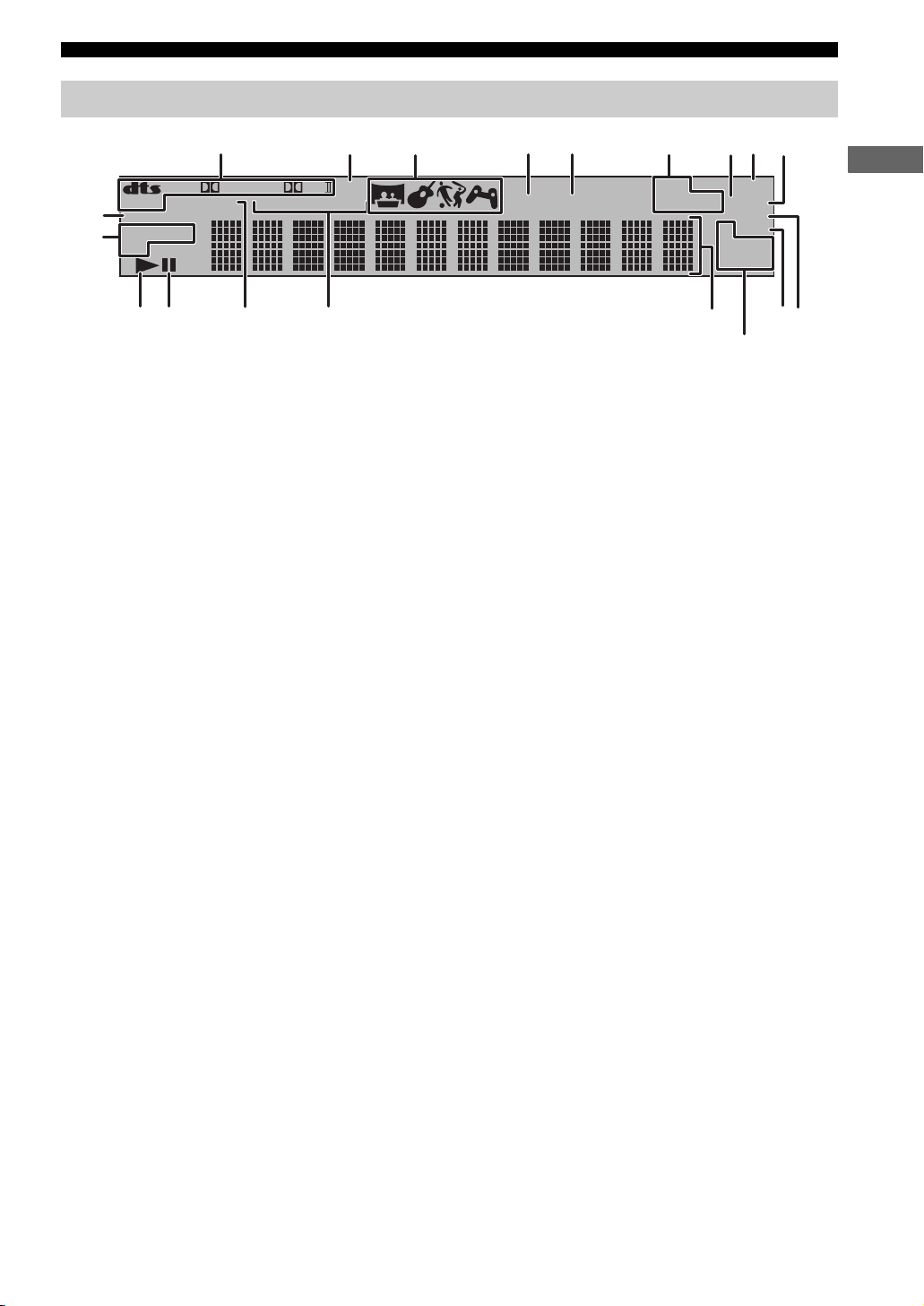
1 Decoder indicator
Displays the icon for the selected internal decoder.
2 DSP
Lights up when a DSP program is selected.
3 DSP program indicator
Displays the icon for the selected DSP program.
4 VIRTUAL
Lights up when Virtual CINEMA DSP is activated.
5 SILENT CINEMA indicator
Lights up when the Silent Cinema mode is activated.
6 Playback mode indicator
Displays the icon for the selected playback mode.
7 AUTO
Lights up when using the Auto Tuning or Auto Preset
mode.
8 SLEEP
Lights up when the Sleep Timer is on.
9 ST
Lights up when receiving a strong FM radio signal in the
Auto Tuning or Auto Preset mode.
0 PROGRESSIVE
Lights up when the progressive scan function is activated.
B Playback icon
Lights up during disc playback.
C Pause icon
Lights up when disc playback is paused.
D PCM
Lights up when playing PCM signals such as CDs.
E Display mode indicator
Displays the indicator for the information type shown in
the CinemaStation display.
F Display
Displays various information such as a title, chapter or
track number, or elapsed playing time.
G TUNED
Lights up when receiving an FM/AM broadcast.
H MEMORY
Blinks when presetting an FM/AM radio station.
■ U.K. and Europe models only
I RDS indicators
Light up when receiving an RDS signal. “PTY HOLD”
lights up when the PTY SEEK mode is activated.
(page 50)
A Disc indicator
Displays the icon for the disc.
5
Controls and Functions
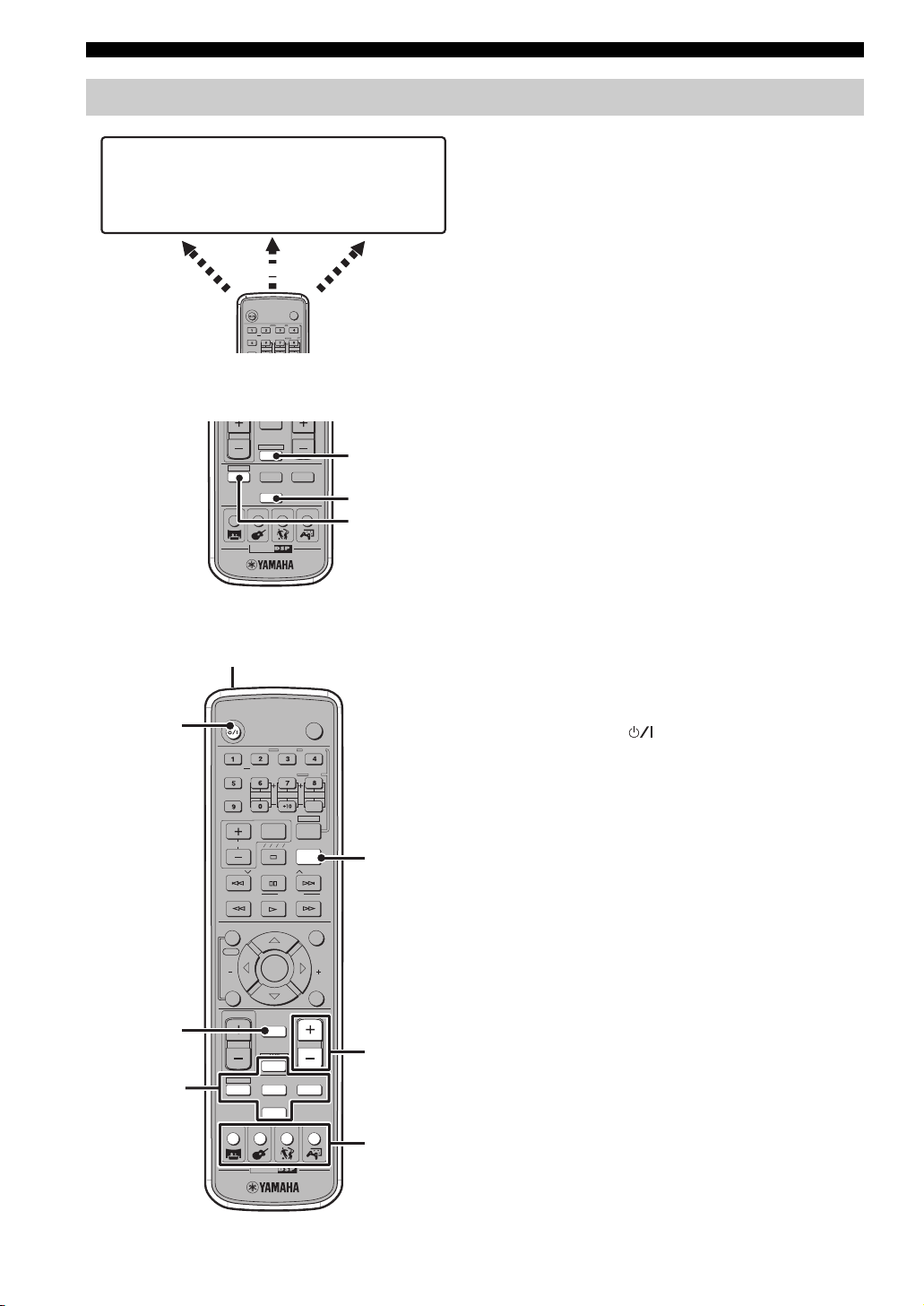
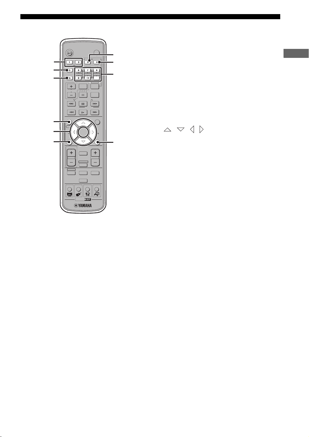
Remote control
AMP
• DSP program
selection
• Input selection,
etc.
Amp mode
DVD/CD
• Playback
• Subtitle and
audio language
selection, etc.
DVD/CD mode
DVR-S120 WB56650
POWER
POWER
TV
SUBTITLE
AUDIO
ANGLE
SELECT
STEREOMATRIX 6.1
SURROUND
A-B
REPEAT
NIGHT
SW
CENTER
SURR
FM/AM
• Radio station
tuning
• Radio station
preset, etc.
Tun er mo de
CinemaStation has three main operation modes. Before
operating functions in each mode, you need to select a
mode to change the remote control button assignments.
To switch the operation mode
• Amp mode: Press AMP. (page 7)
• DVD/CD mode: Press DVD/CD. (page 8)
• Tuner mode: Press TUNER. For details on tuner
operations, refer to “Tuning Radio Stations” (page 48).
y
You can also operate the TV or VCR connected to the
CinemaStation using the remote control. For details, refer to
“Controlling External Components” (page 72).
AMP
DVD/CD
VCR
TUNER
MOVIE MUSIC SPORTS GAME
CINEMA
■ Common functions
1
STANDBY/ON
2
AUDIO
SELECT
SURROUND
NIGHT
SW
SET MENU
TV INPUT
TV CH
A B C D E
PRESET PRESET
FREQ/RDS
MODE
ON SCREEN MENU
START
YPAO
CH
ENTER
STATUS
ON/OFF
TV VOL
3
4
MUTE
AMP
DVD/CD
VCR
TUNER
MOVIE MUSIC SPORTS GAME
CINEMA
ANGLE
REPEAT
CENTER
PTY SEEK
VIDEO
SHIFT
SLEEP
TEST
VOLUME
POWER
TV
SUBTITLE
STEREOMATRIX 6.1
A-B
SURR
START
CH
RETURN
VIDEO
AMP
TUNER
DVD/CD
5
6
7
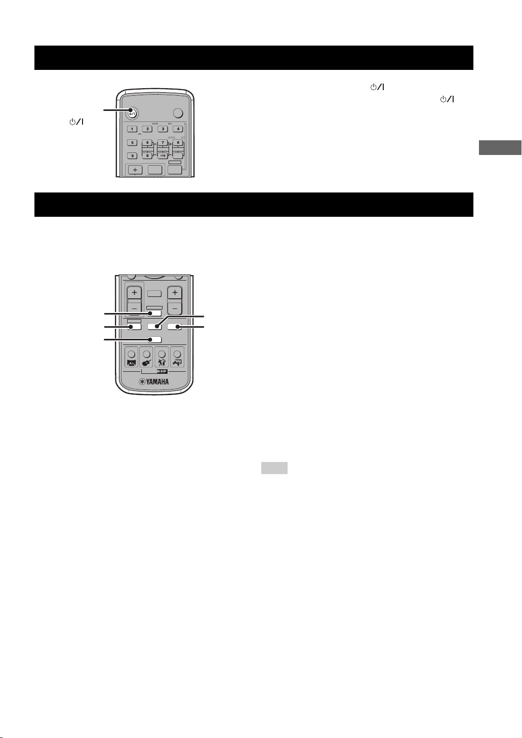
Operations common to all modes
1 Infrared signal transmitter
Sends signals to the CinemaStation.
2 STANDBY/ON ( )
Turn the CinemaStation on, or set it to the standby mode.
(page 19)
3 MUTE
Turns off the volume. Press again to resume the volume.
4 Input selection buttons
Select an input source to operate. (page 19)
5 SLEEP
Sets the Sleep Timer. (page 28)
6 VOLUME +/–
Adjusts the overall volume level.
7 DSP program buttons
Selects a DSP program. (page 26)
6
Controls and Functions
■ Amp mode Operations available only in amp mode
1 SURROUND, SELECT
Sets Dolby Digital or DTS. Press SURROUND and then
SELECT to set Dolby Pro Logic II for 2ch sources.
(page 58)
2 NIGHT
Sets the CinemaStation to the Night Listening mode.
(page 61)
3 SET MENU
Enters the Set Menu. (page 76)
4 YPAO
Starts the YPAO function. (page 21)
5 / / /
Adjusts the test tone (page 64) or Set Menu (page 76).
6 ON/OFF
Turns the YPAO mode on/off. (page 23)
7 MATRIX 6.1
Sets the Matrix 6.1 decoder. (page 57)
8 STEREO
Switches between normal stereo sound and audio with a
sound field effect. (page 63)
9 Speaker volume buttons
Adjusts the speaker balance (volume level of each
speaker). (page 65)
SW +/–: Adjusts the subwoofer volume.
CENTER +/–: Adjusts the center speaker volume.
SURR +/–: Adjusts the surround speaker volume.
0 TEST
Outputs a test tone. (page 64)
y
Amp mode operations are indicated in purple on the remote
control.
1
2
3
4
5
6
STANDBY/ON
SURROUND
NIGHT
SET MENU
TV CH
PRESET PRESET
FREQ/RDS
ON SCREEN MENU
START
YPAO
CH
STATUS
ON/OFF
TV VOL
DVD/CD
MOVIE MUSIC SPORTS GAME
AUDIO
SELECT
SW
A B C D E
CINEMA
TV INPUT
MODE
ENTER
MUTE
AMP
VCR
TUNER
ANGLE
REPEAT
CENTER
PTY SEEK
TEST
VOLUME
POWER
SUBTITLE
SHIFT
SLEEP
VIDEO
STEREOMATRIX 6.1
SURR
START
TV
A-B
CH
RETURN
7
8
9
0
INTRODUCTION
7
Controls and Functions
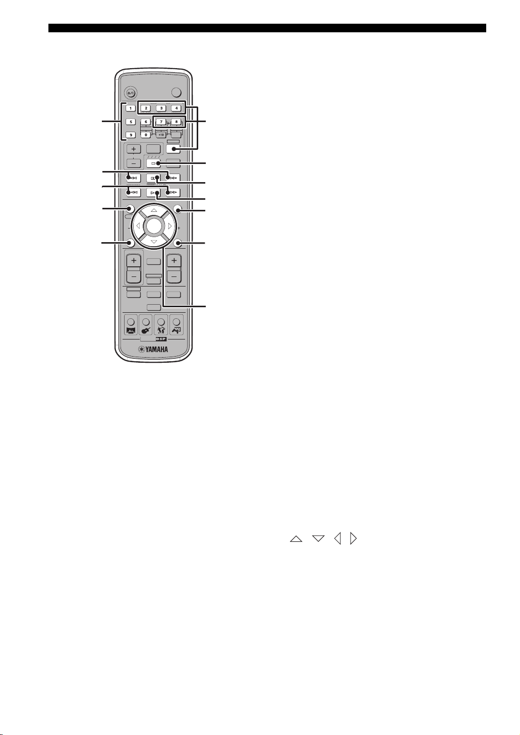
■ DVD/CD mode Operations available only in DVD/CD mode
1 Number buttons (1 to 9, 0)
STANDBY/ON
16
2
3
4
5
SURROUND
NIGHT
SET MENU
TV CH
PRESET PRESET
FREQ/RDS
ON SCREEN MENU
START
YPAO
CH
STATUS
ON/OFF
TV VOL
DVD/CD
MOVIE MUSIC SPORTS GAME
AUDIO
SELECT
SW
CINEMA
TV INPUT
A B C D E
MODE
ENTER
MUTE
AMP
VCR
TUNER
ANGLE
REPEAT
CENTER
PTY SEEK
SHIFT
SLEEP
TEST
VOLUME
VIDEO
POWER
TV
SUBTITLE
STEREOMATRIX 6.1
A-B
SURR
START
CH
RETURN
7
8
9
0
A
B
Inputs numerals to specify parameters such as track or
chapter numbers.
2 b, a
Skips to the start of current track or next track.
3 w, f
Fast forwards/fast reverses.
4 ON SCREEN
Displays the On-Screen Menu on the TV screen. (page 29)
5 STATUS
Displays the status information such as disc type, total
time or elapsed time of current track/chapter on the TV
screen. To display the status information, the “Status
window” setting in the On-Screen Menu (page 29) should
be set to “On”.
6 Settings buttons
While holding down SHIFT, press a button below to
enable the corresponding operation.
REPEAT: Enables the Repeat Play mode. (page 37)
A-B: Enables the A-B Repeat mode. (page 38)
AUDIO: Selects the audio language of the DVD video.
(page 40)
ANGLE: Selects the disc viewing angle. (page 41)
SUBTITLE: Selects the subtitle language of the DVD
video. (page 40)
7 s
Stops disc playback.
8 e
Pauses disc playback or advances to the next frame.
9 h
Starts disc playback.
0 MENU
Displays the DVD menu on the TV screen. (page 39)
A RETURN
Returns the DVD menu to the previous screen. (page 39)
B / / / / ENTER
Operates the On-Screen Menu (page 29) or specify
various parameters.
y
DVD/CD mode operations are indicated in green on the remote
control.
8
CONNECTING SPEAKERS
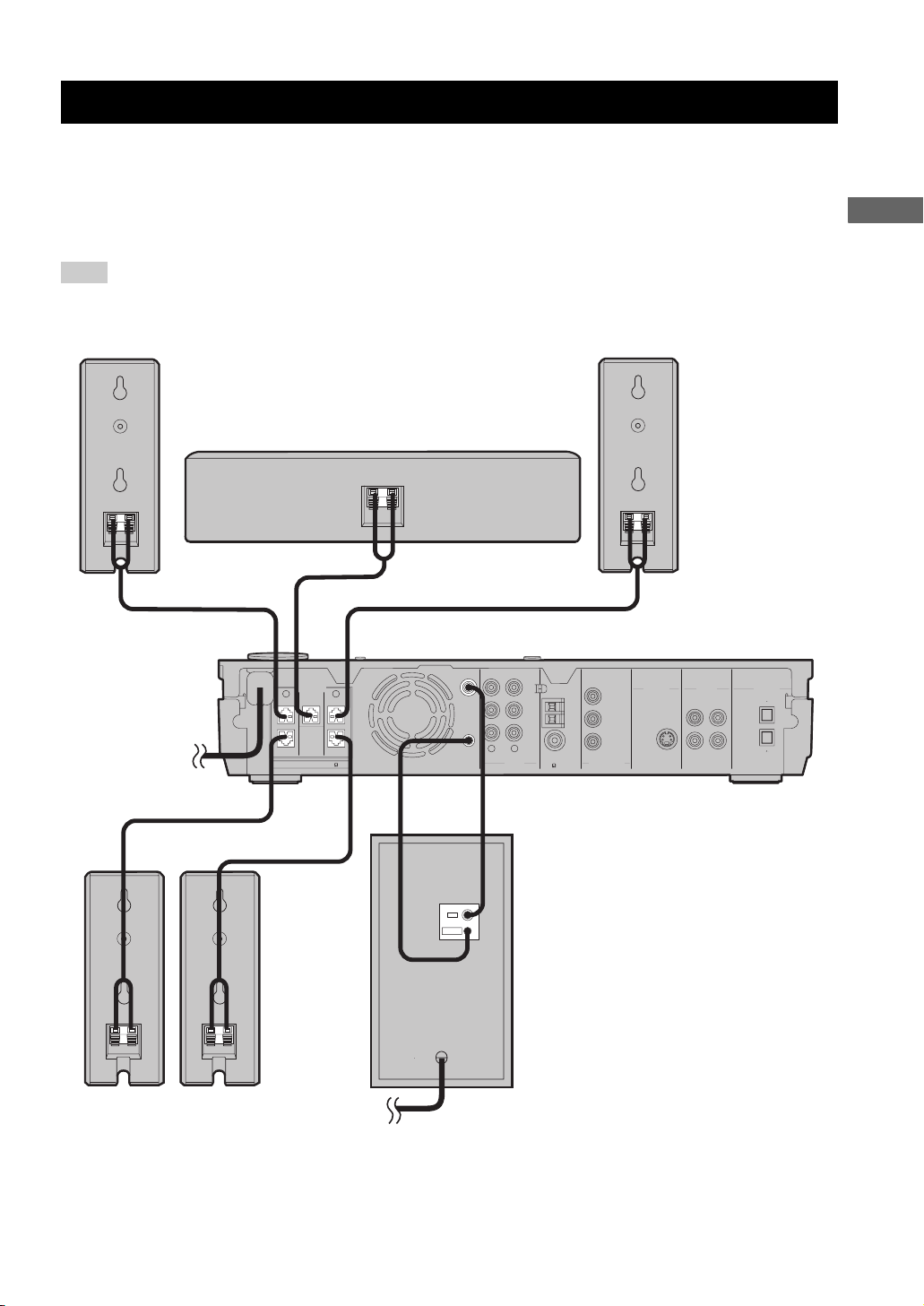
Connecting Speakers
Follow the procedure below to connect speakers to the CinemaStation. Here, the connection example uses the YAMAHA
NX-P150 (consisting of four satellite speakers, a center speaker and a subwoofer) and its supplied cables. For
information on your speakers, refer to the owner’s manual for the speakers.
y
You can also use commercially available speakers and cables (see page 11).
Note
Do not connect the power cable of the CinemaStation until all cable connections are completed.
PREPARATION
Front R speaker
Speaker cable
(cable plug: red)
Speaker cable
(cable plug: gray)
SPEAKERS
FRONT
CENTER FRONT
SURROUND
SPEAKER IMPEDANCE: 6 MIN.
Speaker cable
(cable plug: blue)
Center speaker
SURROUND
Speaker cable
(cable plug: green)
Speaker cable
(cable plug: white)
SUBWOOFER
OUT
RLRL
SYSTEM
CONNECTOR
System
control
cable*
AUDIO
Subwoofer
cable*
VCR
OUT
VCR
IN
VIDEO
IN
Front L speaker
AM
ANT
GND
FM
ANT
75 UNBAL
MONITOR
OUT
(DVD ONLY)
Y
P
B
PR
COMPONENT
VIDEO
MONITOR
OUT
(DVD ONLY)
CinemaStation
VIDEOS VIDEO
MONITOR
VCR
OUT
OUT
VCR
VIDEO
IN
IN
DIGITAL
AUDIO
IN
OUT
OPTICAL
Surround R
speaker
Surround L
speaker
* Supplied with the subwoofer.
SYSTEM
CONNECTOR
INPUT
Subwoofer
9
Connecting Speakers
N
7
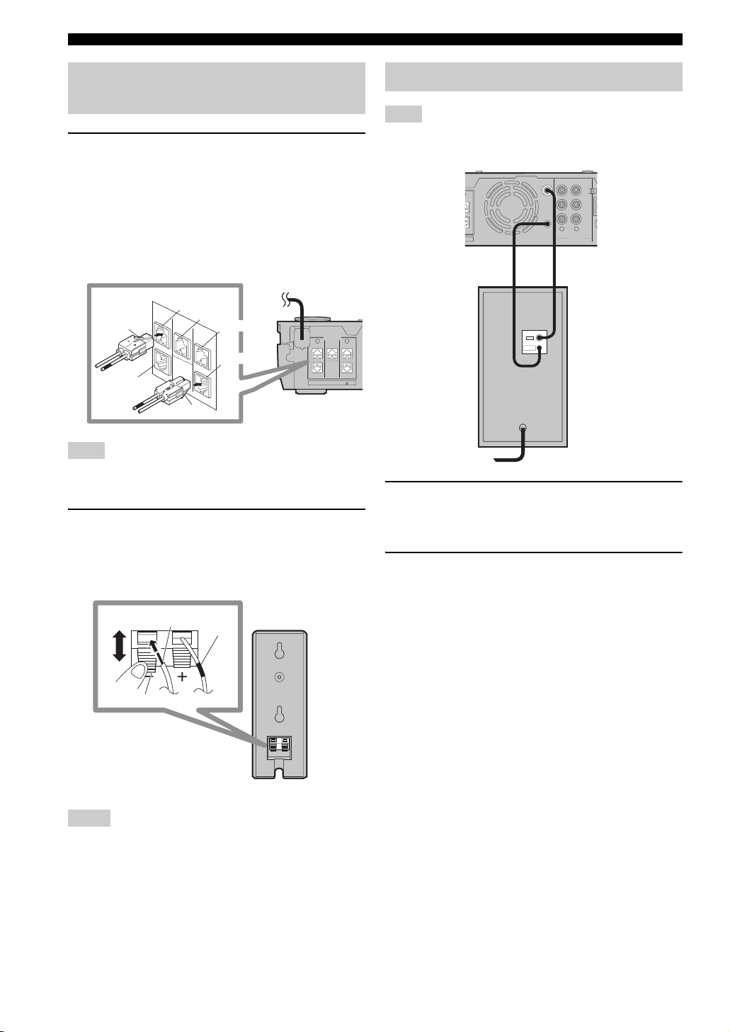
Connecting speakers (Front/Surround/Center)
1 Insert the cable plug of the speaker cable
into the speaker jack of the same color until
you hear it click into place.
• FRONT R (Red), CENTER (Green), FRONT L
(White): Insert the cable plug facing the tub
upwards.
• SURROUND R (Gray), SURROUND L (Blue):
Insert the cable plug facing the tub downwards.
Red
Tab
Green
Color
band
White
Blue
SPEAKERS
FRONT
CENTER FRONT
SURROUND
SURROUND
SPEAKER IMPEDANCE: 6 MIN.
LR
Tab
Gray
Note
Do not use excessive force when inserting the cable plug. Doing
so may damage the cable plug or speaker jack.
2 Connect the cable core of the speaker cable
with the color band to the + connector on the
speaker and other cable core to the –
connector.
Cable core
Connecting a subwoofer
Note
Do not connect the power cable of the CinemaStation or
subwoofer until all cable connections are completed.
SUBWOOFER
T
UND
MIN.
OUT
SYSTEM
CONNECTOR
System
control
cable
INPUT
SYSTEM
CONNECTOR
1 Connect the SUBWOOFER OUT jack on the
CinemaStation to the INPUT jack on the
subwoofer using the subwoofer cable.
2 Connect the SYSTEM CONNECTOR jack on
the CinemaStation to the SYSTEM
CONNECTOR jack on the subwoofer using
the system control cable.
VCR
OUT
VCR
IN
VIDEO
IN
RL
AUDIO
Subwoofer
cable
Subwoofer
Lever
Press the lever
down, then insert the
cable core into the
hole and release the
lever.
Notes
• Do not allow the cable cores to touch each other or any metal
part. Doing so may damage the unit or speakers.
• Make sure you connect the cable cores to the correct
connectors. Reversed connections may produce unnatural
sounds during playback.
10
Connecting Speakers
Using commercially available speakers or cables
When using speakers or cables other than those of the
YAMAHA NX-P150 (consisting of four satellite speakers,
a center speaker and a subwoofer) and its supplied cables,
be careful of the following. When using a commercially
available speaker cable, remove the cable plug from one of
the supplied speaker cables and attach it to the cable you
are using.
When using commercially available speakers
• Use speakers with 6-ohm impedance or more. If a
speaker with less than 6-ohm impedance is used, the
protective circuit may trip or the speaker may
malfunction.
• Use magnetically shielded speakers to prevent
interferences with a TV. If these speakers still interfere
with a TV, move the speakers a little away from the TV.
• We recommend using speakers of the same
manufacturer that have identical sound qualities. If
they are mixed, certain sounds may be heard
unnaturally.
• Use speaker cables that are the same thickness as the
supplied cables.
When using commercially available speaker
cables
• Use speaker cables that are the same thickness as the
supplied cables.
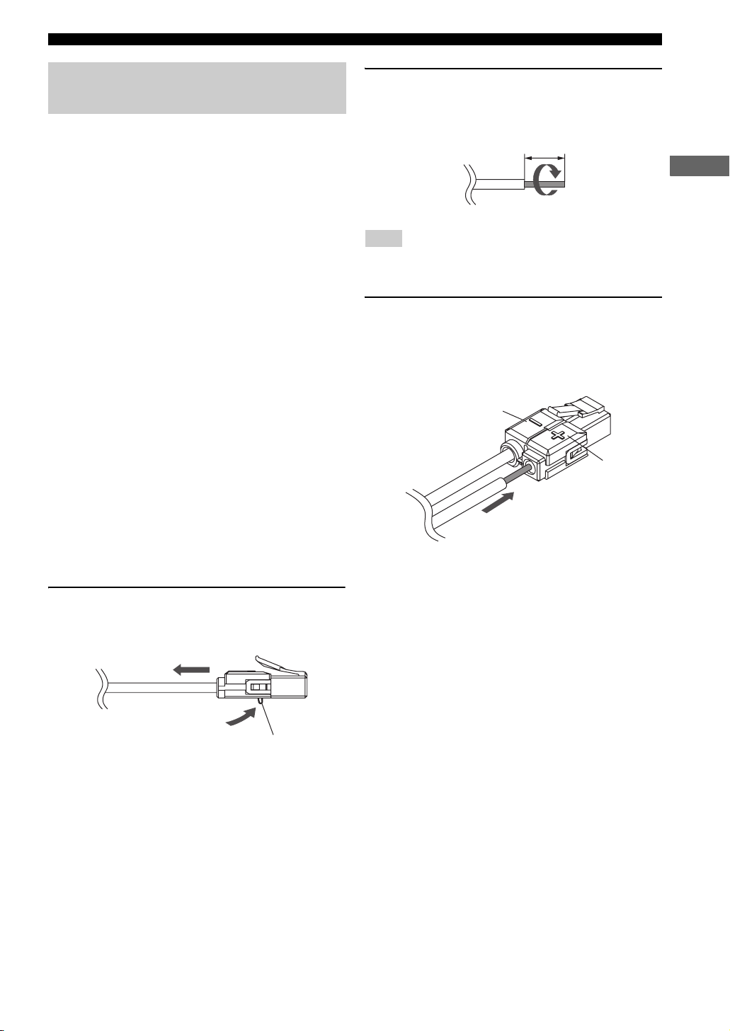
2 Peel away about 10 mm (10/32”) of covering
from the tip of the new cable and twist the
cable core firmly in a clockwise direction.
10 mm (10/32”)
PREPARATION
Clockwise
Note
Be sure to twist the cable core firmly in a clockwise direction.
Twisting loosely may cause a short.
3 Press and hold the release button, insert the
cable core into the cable plug, then release
the button.
Match the speaker cable polarity (+/–) with the
polarity mark (+/–) of the cable plug.
Polarity mark –
Polarity mark +
■ To replace speaker cables
1 Press and hold the release button and
remove the supplied speaker cable from the
cable plug.
Release button
11
CONNECTING A TV
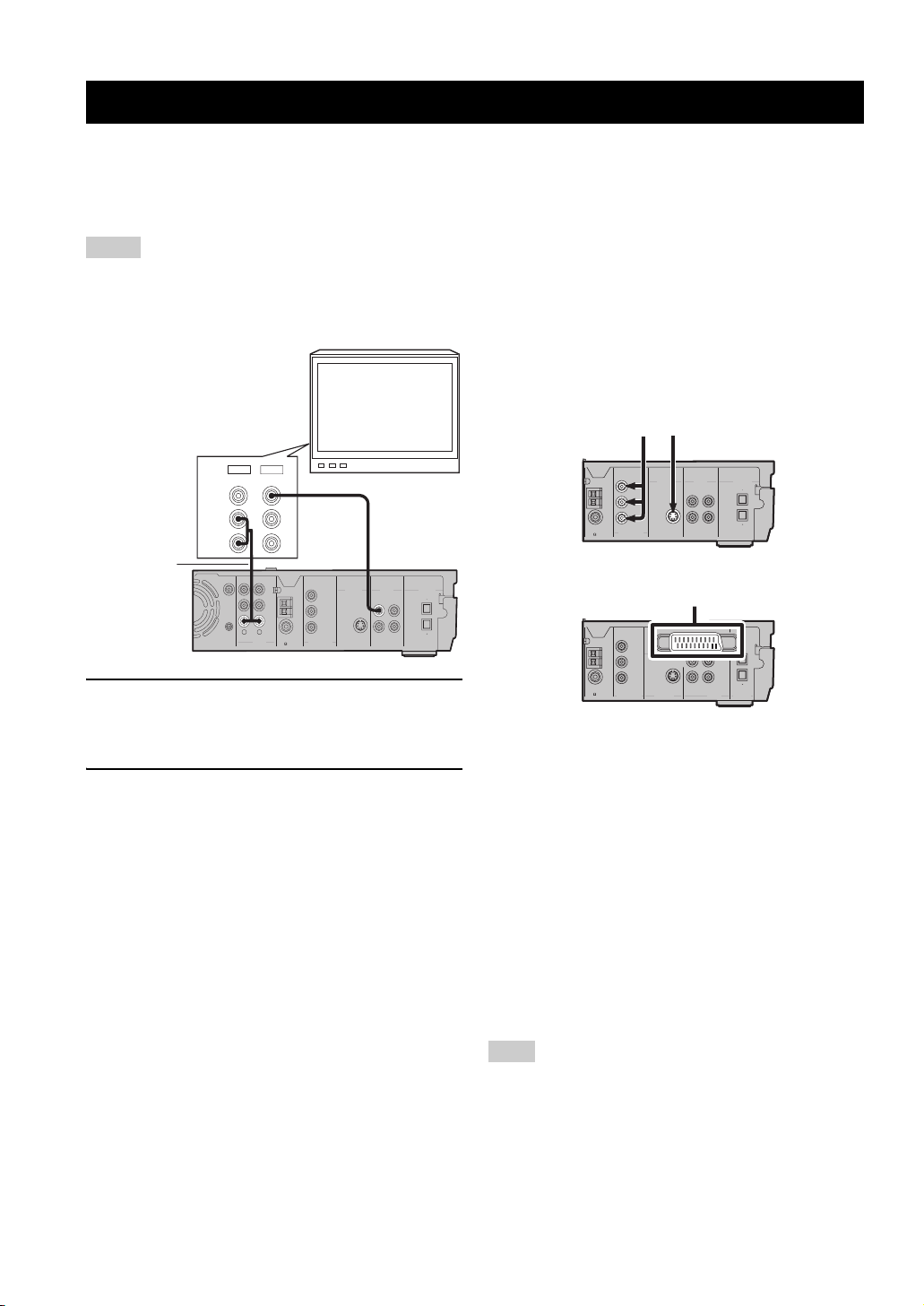
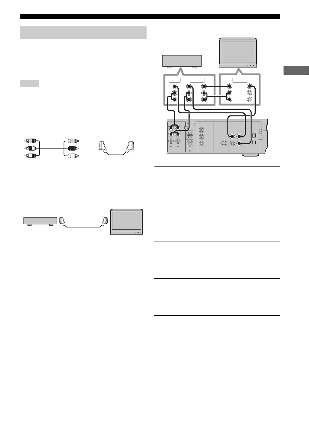
Connecting a TV
Follow the procedure below to connect your TV to CinemaStation using the supplied video pin cable. If you want to
output sound from the speakers connected to CinemaStation, prepare a commercially available audio pin cable to connect
them. Also, you can enjoy high-quality pictures with the component video, S-Video, or SCART (U.K. and Europe
models only) connection. For information about your TV, refer to the supplied manual.
Notes
• Do not connect the power cable of the CinemaStation until all cable connections are completed.
• Turn off the TV before connecting it to the CinemaStation.
TV
OUT
IN
2 Audio cable
(commercially
VIDEO
AUDIO
L
R
1 Video pin
cable
(supplied)
available)
SUBWOOFER
OUT
SYSTEM
CONNECTOR
RL
AUDIO
MONITOR
OUT
(DVD ONLY)
VCR
OUT
Y
AM
VCR
ANT
IN
VIDEO
IN
75 UNBAL
MONITOR
OUT
P
B
GND
(DVD ONLY)
FM
P
R
ANT
COMPONENT
VIDEO
MONITOR
DIGITAL
VIDEOS VIDEO
AUDIO
VCR
IN
OUT
OUT
OUT
VCRINVIDEO
OPTICAL
IN
1 Connect the MONITOR OUT (VIDEO) jack on
the CinemaStation to the video input jack on
your TV using the supplied video pin cable.
2 To output sound from the speakers
connected to CinemaStation, connect the
VIDEO IN L/R (AUDIO) jacks on the
CinemaStation to the audio output L/R jacks
on your TV using the commercially available
audio pin cable.
■ Other connection methods
To make a component video, S-Video, or SCART (U.K.
and Europe models only) connection, a corresponding
cable is required.
Component video S-Video
MONITOR
OUT
(DVD ONLY)
Y
AM
ANT
MONITOR
OUT
B
P
GND
(DVD ONLY)
FM
PR
ANT
COMPONENT
VIDEO
75 UNBAL
SCART
AV MONITOR OUT
MONITOR
OUT
(DVD ONLY)
Y
AM
75 UNBAL
ANT
GND
FM
ANT
COMPONENT
VIDEO
MONITOR
P
B
OUT
MONITOR
OUT
PR
(DVD ONLY)
S VIDEO
(U.K. and Europe models)
Component video
Connect the MONITOR OUT Y/P
VIDEO) jacks on the CinemaStation to the component
video input Y/P
B/PR jacks on your TV using a
commercially available component video cable.
S-Video
Connect the MONITOR OUT (S VIDEO) jack on the
CinemaStation to the S-Video input jack on your TV using
a commercially available S-Video cable.
DIGITAL
VIDEOS VIDEO
AUDIO
MONITOR
VCR
IN
OUT
OUT
OUT
VCRINVIDEO
OPTICAL
IN
(DVD ONLY)
IN
VCR
OUT
VCR
IN
OUT
VIDEO
OPTICAL
IN
DIGITAL
VIDEO
AUDIO
B/PR (COMPONENT
12
SCART (for U.K. and Europe models)
Connect the AV MONITOR OUT jack on the
CinemaStation to the SCART input jack on your TV using
a commercially available SCART video cable.
Note
(For U.K. and Europe models)
If you set the Video Output setting to “RGB” in the On-Screen
Menu (page 29), the MONITOR OUT (S VIDEO) jack cannot
output video signals.
CONNECTING ANTENNAS
Connecting Antennas
To enjoy radio on the CinemaStation, you need to connect AM and FM antennas to the CinemaStation. This product
includes an AM loop antenna and indoor FM antenna. If there is a problem of weak radio wave reception in your area or
you want to improve radio reception, we recommend that you use optional outdoor antennas. For details, consult the
nearest authorized YAMAHA dealer or service center.
PREPARATION
Indoor FM
antenna
(supplied)
AM
ANT
GND
O
FM
ANT
75 UNBAL
MONITOR
OUT
(DVD ONLY)
Y
P
B
PR
COMPONENT
VIDEO
MONITOR
OUT
(DVD ONLY)
MONITOR
OUT
VIDEO
IN
VIDEOS VIDEO
VCR
OUT
VCR
IN
AM loop
antenna
(supplied)
DIGITAL
AUDIO
IN
OUT
OPTICAL
Ground (GND terminal)
■ About grounding
For maximum safety and minimum interference, connect
the antenna GND terminal to a good earth ground. A good
earth ground is a metal stake driven into moist earth.
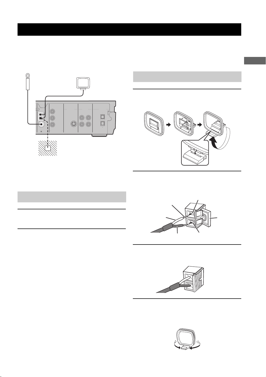
Connecting the FM antenna
1 Connect the supplied indoor FM antenna to
the FM ANT jack on the CinemaStation.
Connecting the AM loop antenna
1 Attach the antenna stand to the antenna.
When attaching the antenna to the wall, you do not
need to use the antenna stand.
2 Open the lever to the right and insert the
antenna’s cord cores into the AM ANT and
GND terminals.
AM ANT terminal
Cord Core
White
Lever
2 Place the antenna away from the
CinemaStation and speaker cables.
Black
GND terminal
3 Close the lever and then pull the cord lightly
to make sure it is fastened properly.
4 Place the antenna away from the
CinemaStation and speaker cables.
While listening to the radio, rotate the antenna head
to find the best angle for reception.
13
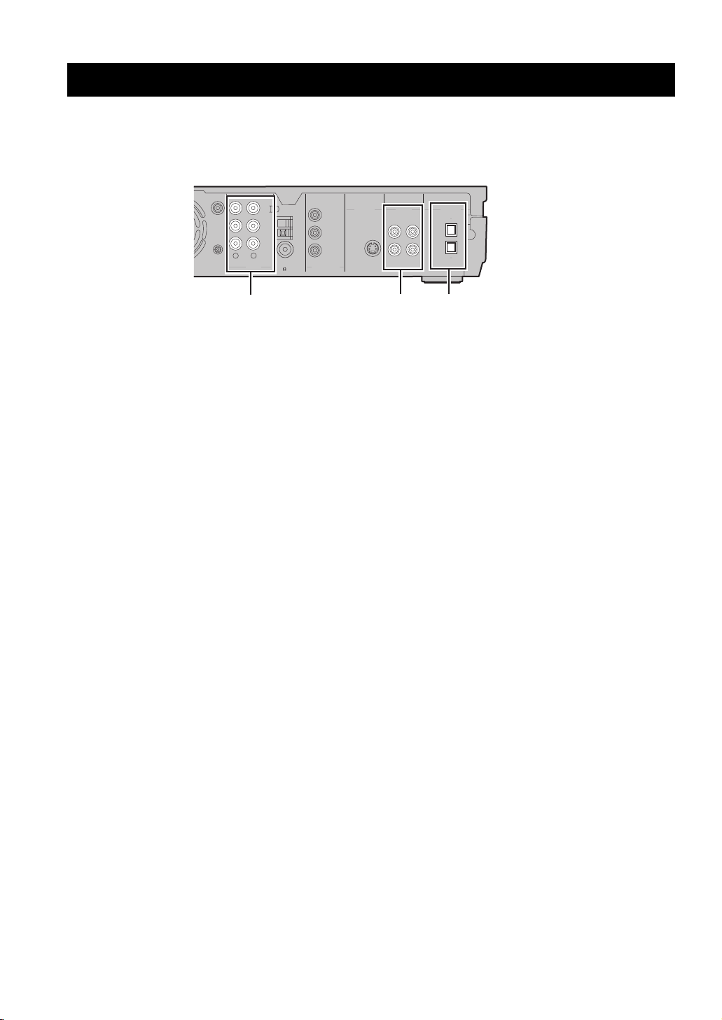
CONNECTING EXTERNAL AV COMPONENTS
Connecting External AV Components
If you connect external AV equipment such as a VCR, video camera, or game console to the following AV jacks on the
CinemaStation, you can enjoy those AV sources with the CinemaStation. Also, you can record AV sources played on the
CinemaStation using the recording equipment. This section provides some examples of other AV equipment connections.
For information on your AV equipment, refer to the manual for it.
75 UNBAL
ANT
GND
ANT
AM
FM
MONITOR
OUT
(DVD ONLY)
Y
P
B
PR
COMPONENT
VIDEO
MONITOR
(DVD ONLY)
SUBWOOFER
OUT
SYSTEM
CONNECTOR
RL
AUDIO
VCR
OUT
VCR
VIDEO
IN
IN
AUDIO jacks
■ About the AUDIO jacks
• You cannot use both IN and OUT jacks for a same
category simultaneously. For example, the signal input
from the VCR IN jack does not output from the VCR
OUT jack.
• CinemaStation’s digital and analog signal circuits are
independent of each other. Analog input signals can
only output from analog output jacks and digital input
signals can only output from digital output jacks.
■ About the DIGITAL AUDIO jacks
• The digital jacks are compatible with PCM, Dolby
Digital and DTS signals.
• The digital jacks are designed based on EIA standards.
To make a digital connection, use an optical cable that
meets EIA standards.
• The OPTICAL IN jack is compatible with a digital
signal that has a 96 kHz or less sampling frequency.
• You can use “Input Assign” in the Set Menu
(page 78) to assign VIDEO or VCR to the OPTICAL
IN jack. The default setting is “VIDEO”.
VIDEOS VIDEO
MONITOR
OUT
OUT
VIDEO
IN
VIDEO jacks
DIGITAL
AUDIO
VCR
IN
OUT
OUT
VCR
OPTICAL
IN
DIGITAL AUDIO jacks
■ Connecting a TV to an audio input
Enjoy TV sound with CinemaStation by connecting the
TV audio output jack to the AUDIO IN jack using a
commercially available audio cable. Press VIDEO on the
remote control to input TV sound.
14
Connecting External AV Components
Connecting a VCR
If you connect a VCR to the CinemaStation using
commercially available audio/video cables, you can enjoy
videos with the CinemaStation and record AV sources
played on the CinemaStation on the VCR. For information
on your VCR, refer to the owner’s manual for the VCR.
Notes
• Do not connect the power cable of the CinemaStation until all
cable connections are completed.
• Turn off the AV equipment before connecting it to the
CinemaStation.
• Use commercially available audio/video cables (shown below)
to connect a VCR to the CinemaStation or a TV. To make all
connections, three audio/video cables are required.
Audio/Video cable SCART cable
• For U.K. and Europe models only: Do not connect a TV to
CinemaStation via a VCR using SCART connections. The
copyright protection technology incorporated in the
CinemaStation may not allow the VCR to play.
TV
CinemaStation
TV
VCR
IN OUT IN
VIDEO
VIDEO
L
R
AUDIO
AUDIO
5
L
R
VIDEO
LRL
AUDIO
R
4
1
RL
AUDIO
VCR
OUT
VCR
VIDEO
3
AM
ANT
IN
GND
IN
FM
ANT
75 UNBAL
MONITOR
OUT
(DVD ONLY)
Y
B
P
PR
COMPONENT
VIDEO
2
MONITOR
OUT
(DVD ONLY)
MONITOR
OUT
DIGITAL
VIDEOS VIDEO
IN
AUDIO
VCR
IN
OUT
OUT
VCRINVIDEO
OPTICAL
1 Connect the VCR OUT L/R (AUDIO) jacks on
the CinemaStation to the audio input L/R
jacks on your VCR using a commercially
available audio/video cable.
2 Connect the VCR OUT (VIDEO) jack on the
CinemaStation to the video input jack on
your VCR using the audio/video cable (used
in step 1).
PREPARATION
3 Connect the VIDEO IN L/R (AUDIO) jacks on
the CinemaStation to the audio output L/R
jacks on your VCR using another audio/video
cable.
4 Connect the VIDEO IN (VIDEO) jack on the
CinemaStation to the video output jack on
your VCR using the audio/video cable (used
in step 3).
5 To watch videos when the CinemaStation is
turned off, connect the audio and video
output jacks on your VCR to the audio and
video input jacks on your TV using another
audio/video cable.
y
For information on how to connect a TV to CinemaStation, refer
to “Connecting a TV” (page 12).
15
Connecting External AV Components
Connecting a game console
If you connect a game console to the CinemaStation using
a commercially available audio/video cable (for analog
connections) or a video cable and optical cable (for digital
connections), you can enjoy games or videos with the
CinemaStation. For information, refer to the manual
supplied with your game console.
Notes
• Do not connect the power cable of the CinemaStation until all
cable connections are completed.
• Turn off the AV equipment before connecting it to the
CinemaStation.
■ Analog connections
Follow the procedure below to connect a game console or
with an analog connection. If you are using VIDEO IN
(AUDIO) jacks for connecting your TV (page 12),
connect a game console or video camera using digital
connections.
MONITOR
OUT
75 UNBAL
VIDEO
AUDIO
ANT
GND
ANT
AM
FM
(DVD ONLY)
Y
P
B
PR
COMPONENT
VIDEO
MONITOR
OUT
(DVD ONLY)
VIDEOS VIDEO
VCR
MONITOR
OUT
OUT
VCR
VIDEO
IN
IN
2
VCR
OUT
VCR
IN
VIDEO
IN
RL
Game
console
AUDIO
1
L
R
OUTPUT
Note
Use a commercially available audio/video cable (shown below) to
connect your game console to the CinemaStation using analog
connections.
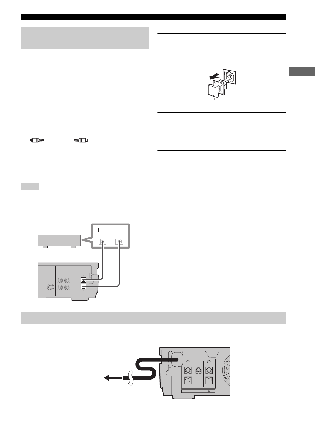
■ Digital connections
Follow the procedure below to connect a game console
using digital connections.
VCR
OUT
VCR
IN
Video pin
cable
DIGITAL
AUDIO
IN
OUT
OPTICAL
Optical
cable
Game console
VIDEO
TOR
T
NLY)
VIDEO
DIGITAL
MONITOR
VIDEO
OPTICAL
OUT
VIDEO
OUT
IN
Note
Use a commercially available video pin cable and an optical cable
(shown below) to connect your game console to the
CinemaStation with a digital connection.
Video pin cable
Optical cable
1 Remove the anti-dust cap from the OPTICAL
IN (DIGITAL AUDIO) jack on the
CinemaStation.
Keep the cap to re-attach it when the jack is not in
use.
Audio/Video cable
1 Connect the VIDEO IN L/R (AUDIO) jacks on
the CinemaStation to the audio output L/R
jacks on your game console using a
commercially available audio/video cable.
2 Connect the VIDEO IN (VIDEO) jack on the
CinemaStation to the video output jack on
your game console using the audio/video
cable (used in step 1).
16
Anti-dust cap
2 Connect the VIDEO IN (VIDEO) jack on the
CinemaStation to the video output jack on
your game console using a commercially
available video pin cable.
3 Connect the OPTICAL IN (DIGITAL AUDIO)
jack on the CinemaStation to the optical
digital output jack on your game console
using a commercially available optical cable.
Connecting External AV Components
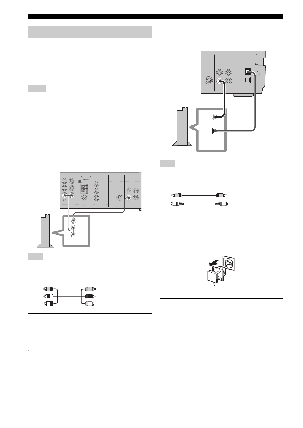
Connecting a CD recorder or MD recorder
If you connect a CD recorder or MD recorder to the
CinemaStation using commercially available optical
cables, you can record audio sources played on the
CinemaStation. Also, you can enjoy audio sources played
on the recorder with the CinemaStation. For information
on your CD recorder or MD recorder, refer to the manual
for it.
y
• Use a commercially available optical cable (shown below) to
connect your CD recorder or MD recorder to the
CinemaStation. To make all connections, two optical cables are
required.
Optical cable
• AM/FM broadcasts cannot be output from this unit’s OPTICAL
OUT (DIGITAL AUDIO) jack. To record AM/FM broadcasts,
use a commercially available audio cable to connect the VCR
OUT jack on the CinemaStation to the analog input jack on
your recorder (see page 55).
Notes
• Do not connect the power cable of the CinemaStation until all
cable connections are completed.
• Turn off the AV component before connecting it to the
CinemaStation.
1 Remove the anti-dust caps from the
OPTICAL (DIGITAL AUDIO) jacks on the
CinemaStation.
Keep the cap to re-attach it when the jack is not in use.
PREPARATION
Anti-dust cap
2 Connect the OPTICAL OUT (DIGITAL AUDIO)
jack on the CinemaStation to the optical
digital input jack on your recorder using a
commercially available optical cable.
3 To listen to audio sources played on the
recorder with the CinemaStation, connect the
OPTICAL IN (DIGITAL AUDIO) jack on the
CinemaStation to the optical digital output
jack on your recorder using another optical
cable.
CD recorder or
MD recorder
OUT
OPTICAL
IN
Optical
cable
Optical
cable
MONITOR
OUT
(DVD ONLY)
MONITOR
OUT
VIDEO
IN
VIDEOS VIDEO
DIGITAL
AUDIO
VCR
IN
OUT
OUT
VCR
OPTICAL
IN
Connecting the Power Cables
After you made all connections, connect the power cables of the CinemaStation and subwoofer.
SPEAKERS
LR
CENTER FRONT
FRONT
To an AC wall outlet
SURROUND
SPEAKER IMPEDANCE: 6 MIN.
SURROUND
17
INSTALLING BATTERIES IN THE REMOTE CONTROL
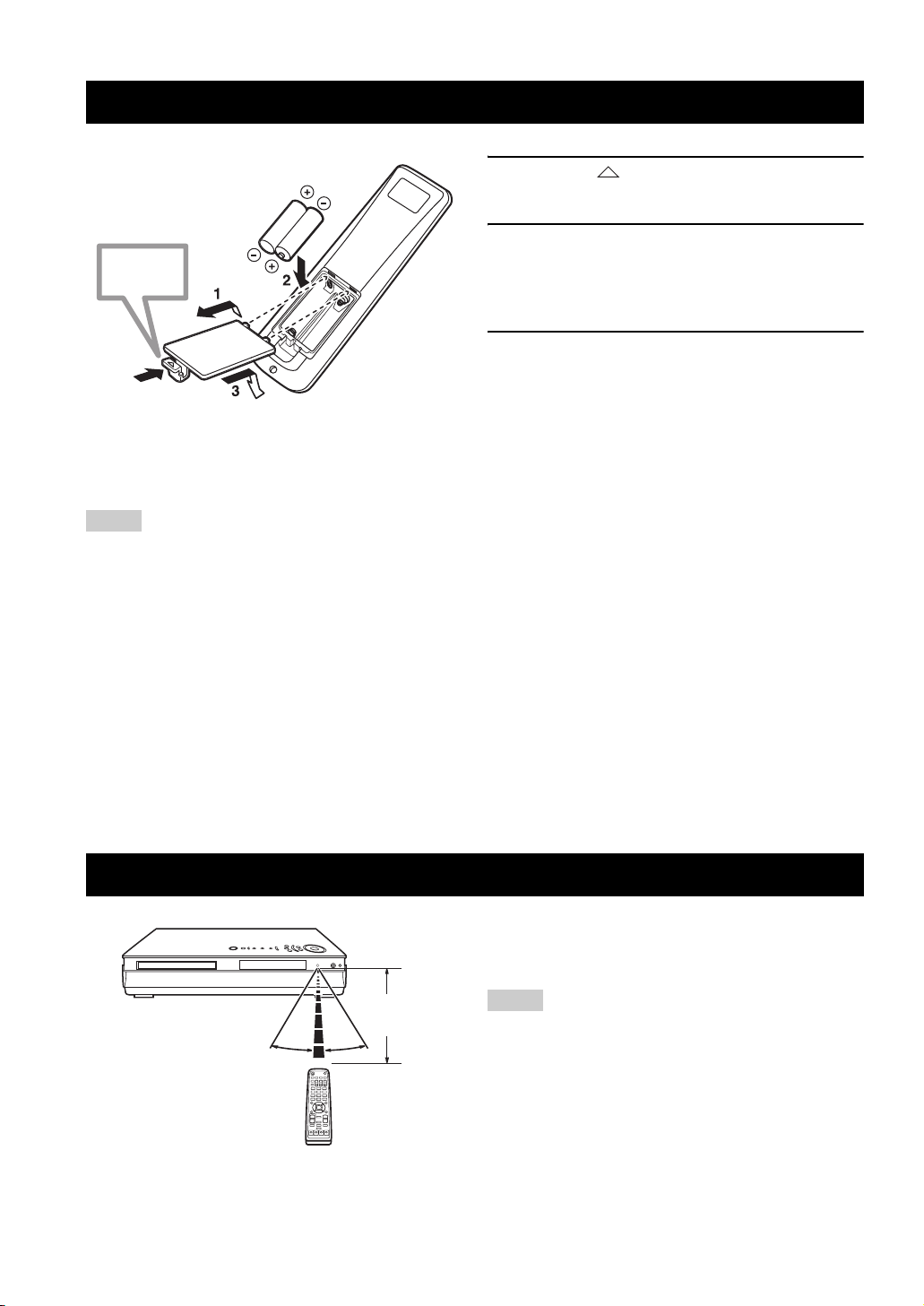
Installing Batteries in the Remote Control
Press %
■ To replace the batteries
If the batteries grow old, the effective operation distance of the
remote control decreases considerably. If this happens, replace
the batteries with two new ones as soon as possible.
Notes
• Do not use an old battery together with new one.
• Do not use different types of batteries (for example, alkaline
and manganese) together. Each type of battery has its own
characteristics even if they are similar in shape.
• If the batteries run out, immediately remove them from the
remote control to prevent an explosion or acid leak.
• Dispose of the batteries according to the regional regulations.
• If a battery starts leaking, dispose of it immediately. Be careful
not to let leaking battery acid come into contact with your skin
or clothing. Before inserting new batteries, wipe the
compartment clean.
• Replace the batteries within two minutes to preserve the
memory in the remote control.
1 Press the mark on the battery cover and
slide off the cover.
2 Insert the two supplied batteries (AA, R06,
UM-3) into the battery compartment.
Make sure you insert the batteries according to the
polarity markings (+ and –).
3 Close the battery cover.
18
Using the Remote Control
Use the remote control within 6 m (20 feet) of the
CinemaStation and point it toward the remote control
sensor (page 4).
Within 6 m
(20 feet)
30˚ 30˚
Notes
• Be careful not to spill liquid on the remote control.
• Be careful not to drop the remote control.
• Do not leave the remote control in the following places:
– hot or humid places, such as near a heater or in a bathroom
– extremely cold places
– dusty places
Turning the Power to On/Standby
Turning the Power to On/Standby
Press STANDBY/ON ( ) once to turn on the
CinemaStation. Press STANDBY/ON ( )
once more to place the CinemaStation in
standby mode.
STANDBY/ON
()
STANDBY/ON
SURROUND
NIGHT
SET MENU
TV CH
AUDIO
SELECT
SW
TV INPUT
ANGLE
REPEAT
CENTER
POWER
TV
SUBTITLE
STEREOMATRIX 6.1
A-B
SURR
SHIFT
Selecting an Input Source
You can enjoy various AV sources with the CinemaStation. After connecting the TV, speakers, antennas, or other AV
equipment, follow the procedure below to select an input source you want to play on the CinemaStation. For information
on connection methods, refer to pages 9 to 17.
Perform one of the following operations
To switch to the CinemaStation amp mode
functions (page 7):
Press AMP.
To switch to DVD/CD input:
Press DVD/CD.
To switch to tuner input (AM/FM radio):
Press TUNER.
To switch to VCR source input (your VCR
connected to the CinemaStation):
Press VCR.
AMP
DVD/CD
TUNER
CINEMA
MUTE
TUNER
TEST
VOLUME
AMP
VIDEO
VCR
ON/OFF
TV VOL
DVD/CD
MOVIE MUSIC SPORTS GAME
VCR
VIDEO
BASIC OPERATION
To switch to video source input (your game
console connected to the CinemaStation):
Press VIDEO.
Note
The CinemaStation itself does not provide video playback or
game features. To play videotapes or games, you need to connect
a VCR or game console to the CinemaStation. For details, refer to
“Connecting External AV Components” (page 14).
19
Adjusting the Volume Level
Adjusting the Volume Level
MUTE
ON/OFF
CINEMA
CINEMA
MUTE
TUNER
TUNER
AMP
VCR
MUTE
TEST
VOLUME
VIDEO
TEST
VOLUME
AMP
VIDEO
VCR
ON/OFF
TV VOL
DVD/CD
MOVIE MUSIC SPORTS GAME
TV VOL
DVD/CD
MOVIE MUSIC SPORTS GAME
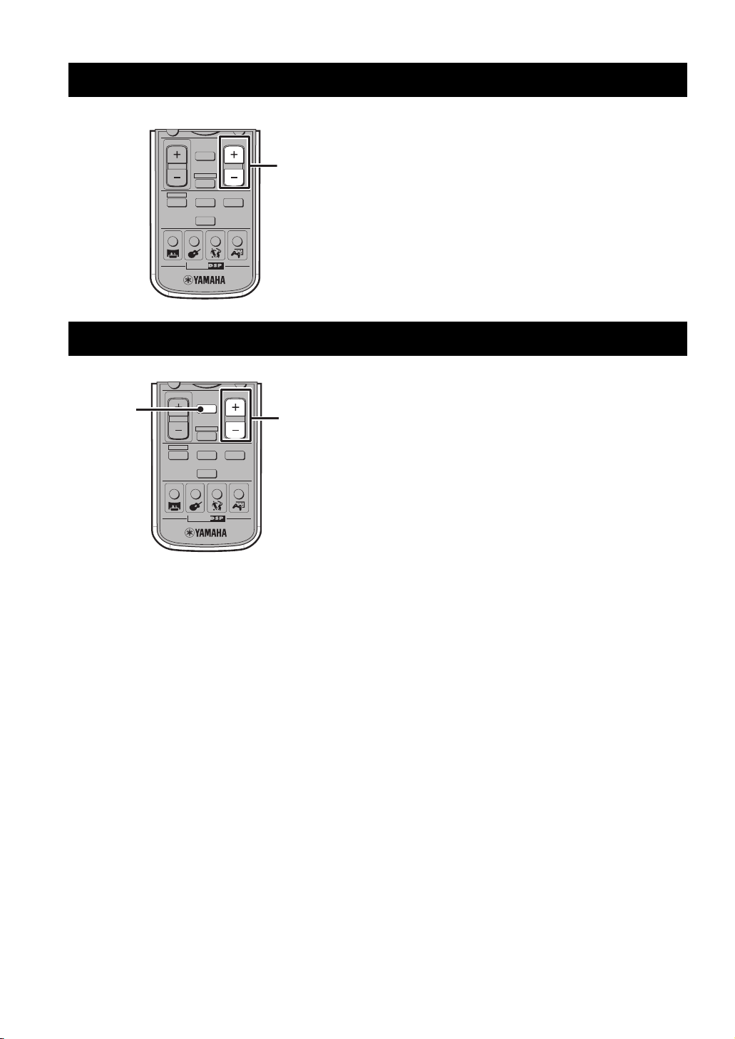
Press VOLUME + to increase the volume level
and VOLUME – to decrease.
VOLUME +/–
Muting the Sound (Mute)
Press MUTE to mute the sound.
To restore audio output to the previous volume level, press
VOLUME +/–
MUTE again or press VOLUME +/–.
20
Auto Speaker Setup (YPAO)
Auto Speaker Setup (YPAO)
With the YAMAHA Parametric Room Acoustic Optimizer (YPAO) feature, you can avoid troublesome speaker setup and
achieve highly accurate sound adjustments. The supplied optimizer microphone collects and analyzes the sound that the
speakers produce in your actual listening environment. We recommend that you perform YPAO each time when you
change the speaker layout or listening position. To configure the speaker settings manually, refer to “Adjusting the
Speaker Balance During Playback” (page 64).
YPAO performs the following adjustments:
YPAO performs the following checks and makes
appropriate adjustments to give you the best possible
sound from your system.
• Wiring/Polarity
Checks which speakers are connected and the polarity
of each speaker. Also checks and adjusts the sound
level (volume) of each speaker so that the sound level
of each speaker is the same when heard from the
listening position.
• Distance/Phase
Checks the distance of each speaker from the listening
position and adjusts the delay of each channel so that
the sound from each speaker reaches the listening
position at the same time. Also checks the phase of
each speaker.
•Size
Checks the speakers frequency response and sets the
crossover/high cut frequency for the subwoofer to
improve the sound relationship between the speakers
and the subwoofer.
y
The CinemaStation stores speaker settings configured by YPAO
and manual setup individually. You can switch between them by
turning on/off the YPAO mode (page 23).
Notes
• Since loud test tones will be output during the setup procedure,
be sure to keep small children out of the room.
• For the best results, make sure the room is as quiet as possible
during the setup procedure. If there is too much noise, the
results may not be satisfactory.
• Disconnect the headphones from the SILENT CINEMA
jack on the CinemaStation before starting the setup procedure.
• Be sure to disconnect the optimizer microphone when you have
completed the setup procedure.
• The optimizer microphone is sensitive to heat. Do not place it
on top of the CinemaStation or in direct sunlight.
1 Make sure the CinemaStation and subwoofer
are turned off (in standby mode).
2 Connect the supplied optimizer microphone
to the YPAO MIC jack on the CinemaStation.
Optimizer microphone
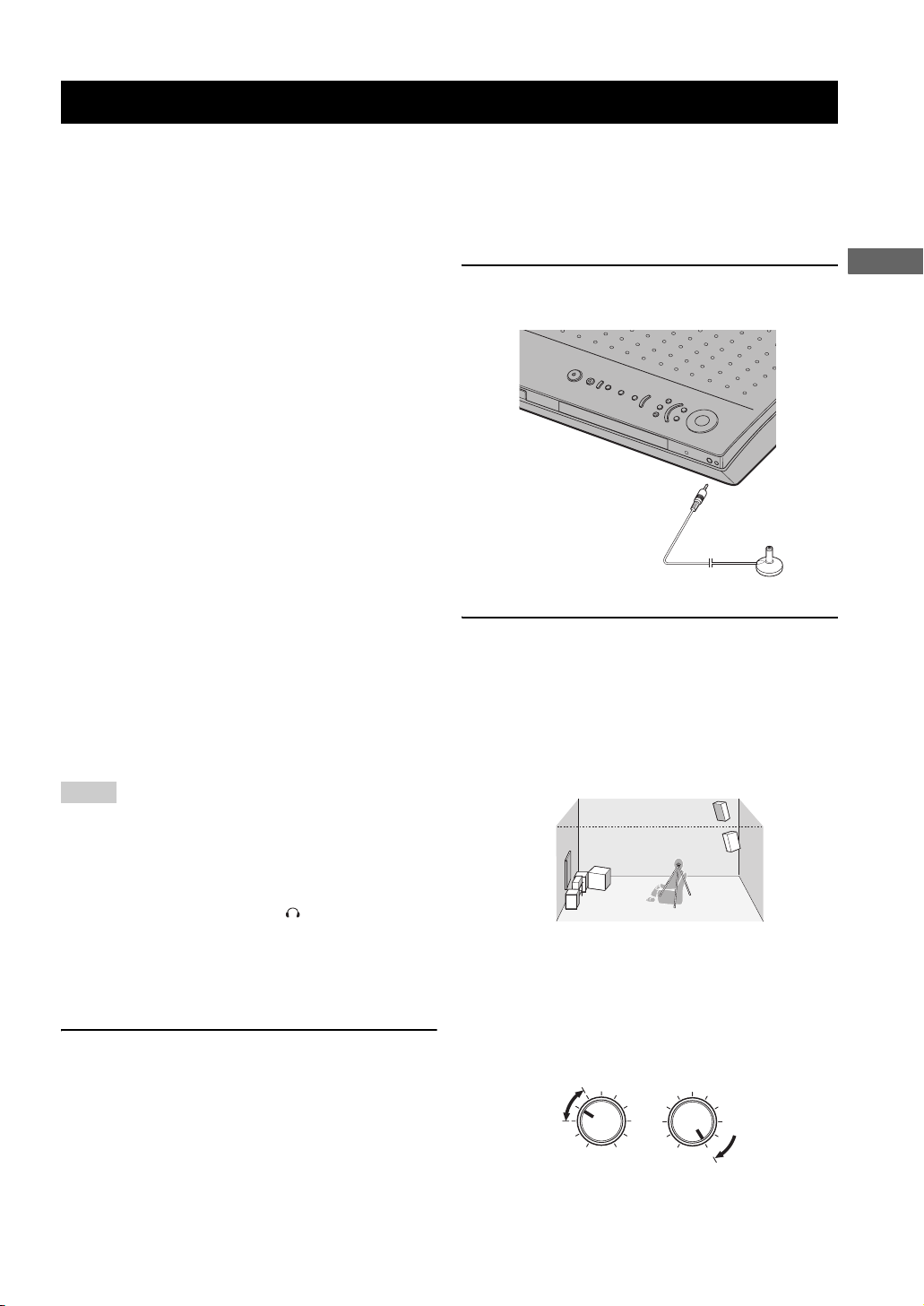
3 Place the optimizer microphone on a flat
level surface with the omni-directional
microphone head upward, at your normal
listening position.
If possible, use a stand such as a tripod to affix the
optimizer microphone at the same height as your ears
would be when you are seated in your listening
position.
Optimizer microphone position
y
If your subwoofer has adjustable volume and crossover/high cut
frequency controls, set the volume low but not minimum
(as shown below) and set the crossover/high cut frequency to the
maximum.
VOLUME
CROSSOVER/
HIGH CUT
BASIC OPERATION
MIN
MAX
Subwoofer
MAX
MIN
21
Auto Speaker Setup (YPAO)
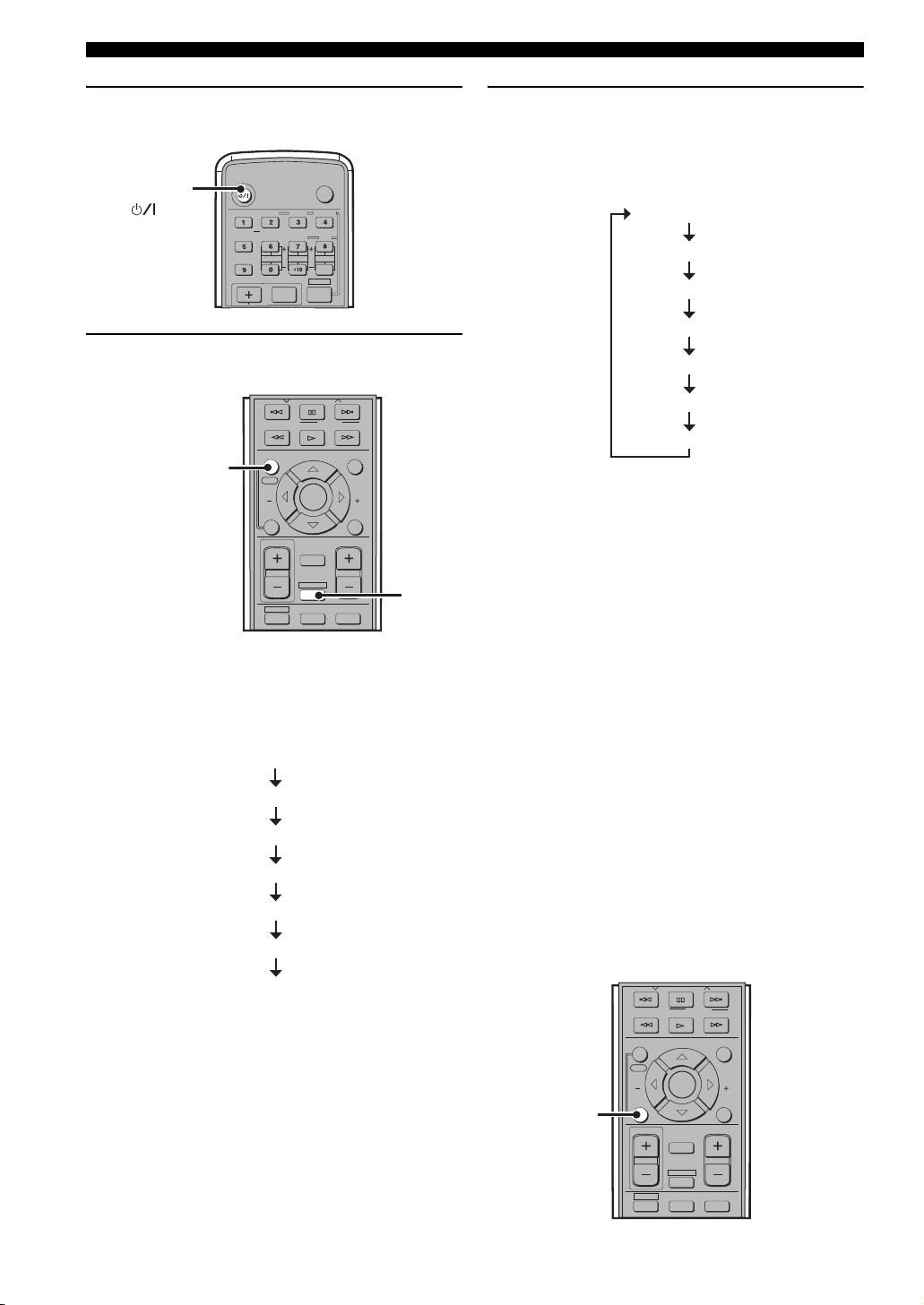
4 Press STANDBY/ON to turn on the
CinemaStation.
STANDBY/ON
()
STANDBY/ON
SURROUND
NIGHT
SET MENU
TV CH
AUDIO
SELECT
SW
TV INPUT
ANGLE
REPEAT
CENTER
POWER
TV
SUBTITLE
STEREOMATRIX 6.1
A-B
SURR
SHIFT
5 Press AMP, then press YPAO to start the
setup procedure.
PRESET PRESET
PTY SEEK
MODE
ENTER
MUTE
START
CHCH
RETURN
TEST
VOLUME
AMP
VIDEO
VCR
AMP
FREQ/RDS
ON SCREEN MENU
YPAO
YPAO
STATUS
TV VOL
DVD/CD
START
ON/OFF
Test tones (the volume is adjustable) are output from
each speaker, and the display changes as follows.
Check that the speaker from which the test tone is
being output and the name of the speaker appearing
in the display are the same.
TEST LEFT
TEST CENTER
TEST RIGHT
TEST R SUR.
TEST L SUR.
TEST SWFR
OK?
6 Press YPAO once more to continue the setup
procedure.
“AUTO SETUP” appears in the display, and
measurement begins. Test tones are output from each
speaker in turn, and the display changes as follows.
TEST LEFT
TEST CENTER
TEST RIGHT
TEST R SUR.
TEST L SUR.
TEST SWFR
OK?
The progress status appears in the display as a
percentage (normally, it takes about two minutes).
If the setup procedure is successful, “YPAO ON” and
the speaker connection status appear alternately in the
display. For information on the speaker connection
status, refer to “Speaker wiring indications” below.
If a warning is detected, “WARNING” and the
speaker connection status appear alternately in the
display. For details, refer to “Error and warning
messages” (page 24).
■ Speaker wiring indications
2.0 F – – – : Front speakers only
2.1 F – – SW : Front speakers and the subwoofer
3.0 F C – – : Front speakers and the center speaker
3.1 F C – SW : Front speakers, center speaker and the
subwoofer
4.0 F – SR – : Front speakers and surround speakers
4.1 F – SR SW : Front speakers, surround speakers and
the subwoofer
5.0 F C SR – : Front speakers, center speaker and
surround speakers
5.1 F C SR SW : Front speakers, center speaker,
surround speakers and the subwoofer
■ To cancel YPAO mode during setup
Press ON/OFF during the setup procedure.
PRESET PRESET
PTY SEEK
MODE
ENTER
MUTE
TEST
VOLUME
START
CHCH
RETURN
ON/OFF
FREQ/RDS
ON SCREEN MENU
START
YPAO
STATUS
ON/OFF
TV VOL
22
DVD/CD
AMP
VIDEO
VCR
■ To turn the YPAO mode on/off
You can switch between speaker settings configured by
YPAO and manual setup by turning on/off the YPAO
mode.
ON SCREEN MENU
START
ON/OFF
YPAO
STATUS
TV VOL
ON/OFF
ENTER
MUTE
AMP
TEST
VOLUME
CHCH
RETURN
AMP
1 Press AMP.
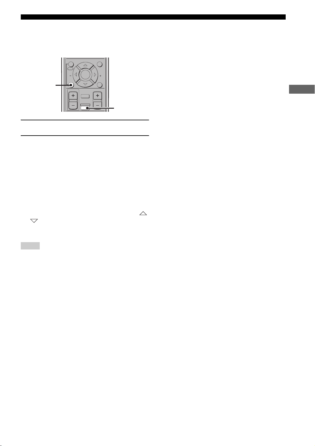
2 Press ON/OFF to display the currently
selected mode, then press ON/OFF again to
select “YPAO ON” or “YPAO OFF”.
• YPAO ON: The CinemaStation uses speaker
settings configured by YPAO. If an error occurs
during testing, this changes to “W YPAO ON”.
• YPAO OFF: The CinemaStation uses speaker
settings configured by manual setup.
y
• If a warning occurs during the YPAO measurement process,
“W YPAO ON” appears in the display. If this happens, use
or to switch the display.
• If you select “YPAO OFF”, settings are returned to their
previously set values.
Auto Speaker Setup (YPAO)
BASIC OPERATION
Notes
• In the YPAO mode, you can make fine adjustments for YPAO
speaker settings such as level and distance, etc.
• If you make fine adjustments to your YPAO speaker settings,
these are reflected whenever you select the YPAO mode.
23
Auto Speaker Setup (YPAO)
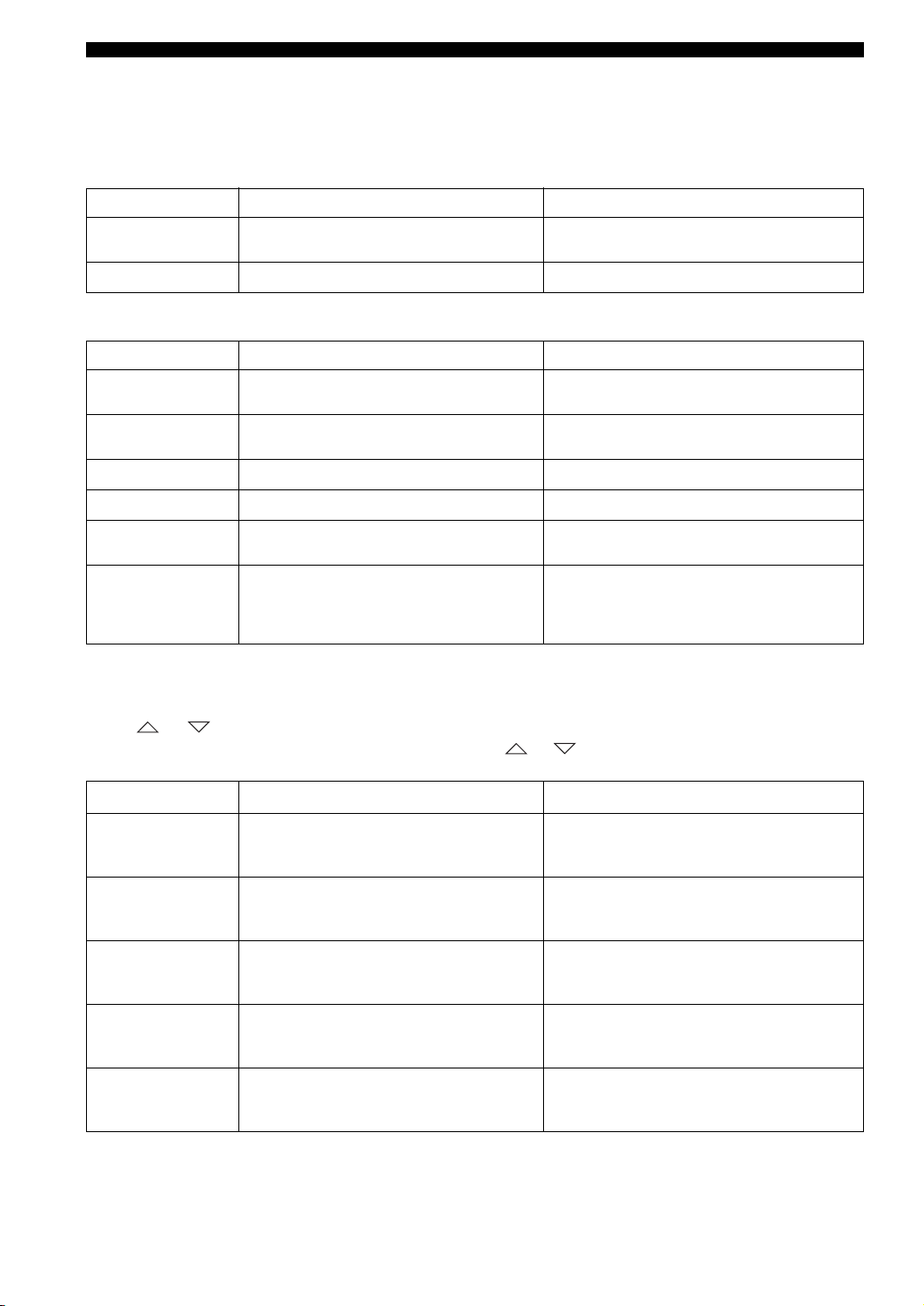
■ Error and warning messages
If an error or warning message appears, check the cause and follow the remedy corresponding to the message, then carry
out the setup procedure once more (page 21).
Error messages before setup
Error message Cause Remedy
Connect MIC
Unplug HP
Error and warning messages during setup
Message Cause Remedy
NO FRONT L
NO FRONT R
NO SURR L
NO SURR R
NO SIGNAL
CANCEL
Optimizer microphone is not connected. • Connect the supplied optimizer microphone to the
Headphones are connected. • Unplug the headphones.
The front left channel signal is not detected. • Select the front speakers with SPEAKER A or B.
The front right channel signal is not detected. • Select the front speakers with SPEAKER A or B.
The left surround channel signal is not detected. • Check the left surround speaker connection.
The right surround channel signal is not detected. • Check the right surround speaker connection.
The optimizer microphone does not detect test tones. • Check the microphone setting.
• The setup procedure was cancelled due to user
activity.
• The setup procedure was cancelled because YPAO
ON/OFF was pressed.
YPAO MIC jack on the front panel.
• Check the front left speaker connection.
• Check the front right speaker connection.
• Check the speaker connections and placement.
• Perform the setup procedure again. Do not adjust
VOLUME (etc.) during the auto setup procedure.
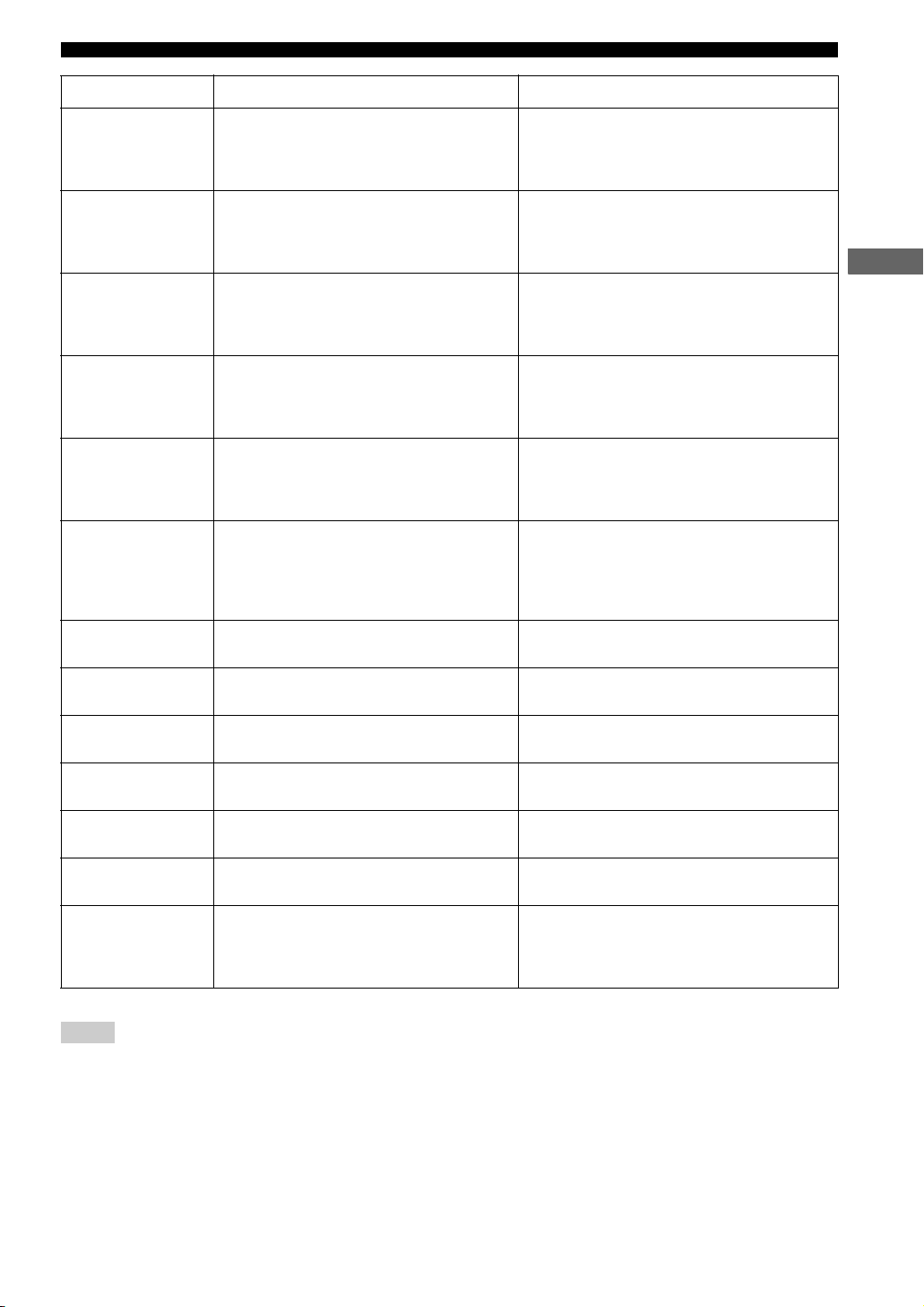
Error messages after setup
If “WARNING” appears in the display after measurement is complete:
Press or .
The error message appears. If multiple errors are detected, press or to switch between them.
Message Cause Remedy
W PHASE L
W PHASE R
W PHASE C
W PHASE SR L
W PHASE SR R
The speaker polarity (+/–) for the front left channel is
incorrect. This message may appear even if the speaker
is connected correctly.
The speaker polarity (+/–) for the front right channel is
incorrect. This message may appear even if the speaker
is connected correctly.
The speaker polarity (+/–) for the center channel is
incorrect. This message may appear even if the speaker
is connected correctly.
The speaker polarity (+/–) for the surround left channel
is incorrect. This message may appear even if the
speaker is connected correctly.
The speaker polarity (+/–) for the surround right
channel is incorrect. This message may appear even if
the speaker is connected correctly.
• Check the speaker connection for the proper polarity
(+ or –).
• Check the speaker connection for the proper polarity
(+ or –).
• Check the speaker connection for the proper polarity
(+ or –).
• Check the speaker connection for the proper polarity
(+ or –).
• Check the speaker connection for the proper polarity
(+ or –).
24
Auto Speaker Setup (YPAO)
Message Cause Remedy
W LEVEL L
W LEVEL R
W LEVEL C
W LEVEL SR L
W LEVEL SR R
W LEVEL SW
W DIST L
The volume level of the front left speaker is outside the
specified range. (No level correction is made.)
The volume level of the front right speaker is outside
the specified range. (No level correction is made.)
The volume level of the center speaker is outside the
specified range. (No level correction is made.)
The volume level of the surround left speaker is outside
the specified range. (No level correction is made.)
The volume level of the surround right speaker is
outside the specified range. (No level correction is
made.)
The volume level of the subwoofer is outside the
specified range. (No level correction is made.)
The front left speaker is placed too far away from the
listening position.
• Readjust the speaker installation so that all speakers are
set in locations with similar conditions.
• Check the speaker connections.
• Use speakers of similar quality and efficiency.
• Readjust the speaker installation so that all speakers are
set in locations with similar conditions.
• Check the speaker connections.
• Use speakers of similar quality and efficiency.
• Readjust the speaker installation so that all speakers are
set in locations with similar conditions.
• Check the speaker connections.
• Use speakers of similar quality and efficiency.
• Readjust the speaker installation so that all speakers are
set in locations with similar conditions.
• Check the speaker connections.
• Use speakers of similar quality and efficiency.
• Readjust the speaker installation so that all speakers are
set in locations with similar conditions.
• Check the speaker connections.
• Use speakers of similar quality and efficiency.
• Readjust the speaker installation so that all speakers are
set in locations with similar conditions.
• Check the speaker connections.
• Use speakers of similar quality and efficiency.
• Adjust the output volume of the subwoofer.
• Bring the speaker closer to the listening position.
BASIC OPERATION
W DIST R
W DIST C
W DIST SR L
W DIST SR R
W DIST SW
W NOISY
The front right speaker is placed too far away from the
listening position.
The center speaker is placed too far away from the
listening position.
The surround left speaker is placed too far away from
the listening position.
The surround right speaker is placed too far away from
the listening position.
The subwoofer is placed too far away from the
listening position.
Background noise is too loud. • Try the setup procedure in a quiet environment.
• Bring the speaker closer to the listening position.
• Bring the speaker closer to the listening position.
• Bring the speaker closer to the listening position.
• Bring the speaker closer to the listening position.
• Bring the subwoofer closer to the listening position.
• Turn off noisy electric equipment like air conditioners
etc., or move them away from the optimizer
microphone.
Notes
• If a phase warning appears, adjustments are made, but they may not be optimal. In this case, follow the remedy and carry out the setup
procedure again (page 21).
• If a level warning appears, no adjustments are made. In this case, follow the remedy and carry out the setup procedure again (page 21).
25
 Loading...