

Page 1
Installation and operation manual
for multi zone
mixing module
MOH2
Page 2
Installation and operation manual MOH2
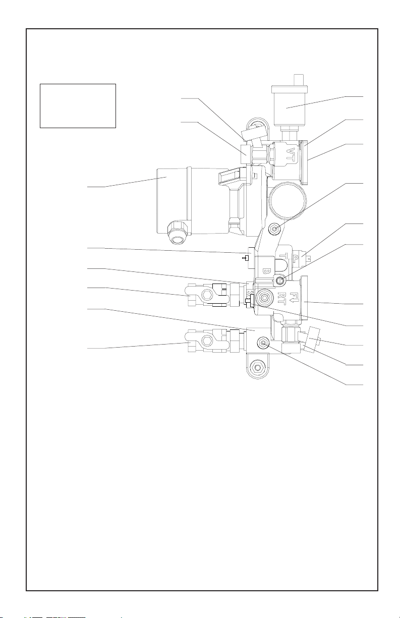
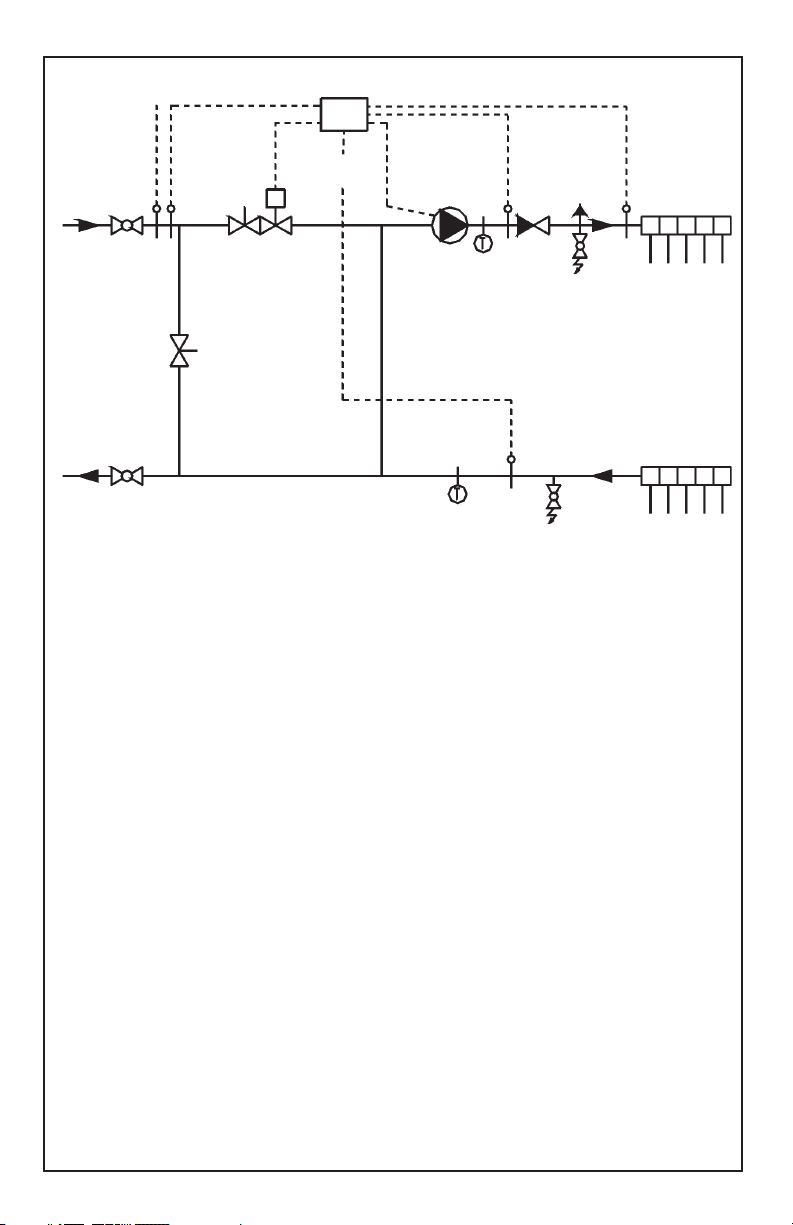
Design MOH2 base module Schematics
Control
11
10
16
12
19
2
7
1
14
5
4
6
9
8
3
15
13
18
17
1 Circulator pump
2 Floor heating loop feed side
3 Floor heating loop return side
4 Control valve
5 Presetting knob for control valve
6 Bypass valve
7 Check valve for filling of floor hea-
ting loops
8 Boiler loop feed side
9 Boiler loop return side
10 Ball valve boiler loop feed side
11 Ball valve boiler loop return side
2
12 Fill valve
13 Drain valve
14 Sensor position for floor heating
loop feed temperature
15 Sensor position for floor heating
loop return temperature
16 Sensor position for safety tempe-
rature
17 Sensor position for boiler feed
temperature
18 Plug for calorimeter dip tube
19 Automatic air purger
www.lainginc.com
Page 3

Installation and operation manual MOH2
Table of contents
Design MOH2 base module .................................................................. 2
Application of the MOH2 mixing module ............................................... 4
Construction .......................................................................................... 4
Function ................................................................................................ 4
Attaching a manifold to the MOH2 to base module ............................... 6
Attaching other kinds of manifolds ........................................................ 7
Changing the number of loops of the segmented plastic manifold ........ 7
Installation of the MOH2 station ............................................................ 8
Hydraulic connection ........................................................................... 10
Connection of calorimeter sensor........................................................ 10
Connection of the controls ...................................................................11
Bypass valve 6 .....................................................................................11
Presetting knob for control valve 5 ...................................................... 13
Filling the system................................................................................. 14
Pressure test ....................................................................................... 14
Start-up ................................................................................................ 15
Technical data ..................................................................................... 16
Dimensions ......................................................................................... 18
Changing out the circulator ................................................................. 19
Troubleshooting................................................................................... 20
www.lainginc.com
3
Page 4

Installation and operation manual MOH2
Application of the MOH2 mixing module
Connection of low temperature heating systems to the boiler loop,
for example
• Floor heating systems
• Wall heating systems
Installation of the MOH2 is possible in the manifold cabinet, because
• It is very compact
• It operates very quietly
• In multifamily dwellings, the feed temperature for the low temperature
loop can be selected individually for each apartment.
Construction
The Laing mixing module MOH2 consist of a bronze cast main body, which
contains [see schematics on page 2]
• Connections for feed and return of the boiler loop
• Connections for feed and return of the low temperature loop
• Circulator
• Control valve
• Presetting knob for control valve
• Air purger as well as fill and drain valves
• Connections for all necessary sensors
• Bypass valve
Function
Floor heating loop
• The circulator 1 circulates the water through the floor heating feed connection and the floor heating loops to the floor heating return connection.
Mixing
• When the mixing valve 4 opens, boiler loop feed water 8 is mixed to the
floor heating loop feed side and the same amount of water is returned
from the floor heating return side 3 to the boiler loop return side 9.
• The mixing valve adjusts the quantity of water coming from the boiler
loop to control the desired floor heating feed temperature.
4
www.lainginc.com
Page 5
Installation and operation manual MOH2
Control
18 16
17
8 10 14 2
5 4 7
1
12
6
15
9 11 3
13
1 Circulator
2 Feed for floor heating circuit
3 Return for floor heating circuit
4 Control valve
5 Presetting knob for control valve
6 Adjustable bypass valve
7 Check valve for filling of floor heating loops
8 Boiler feed connection
9 Boiler return connection
10 Ball valve of boiler feed connection
11 Ball valve of boiler return con-nection
12 Fill valve
13 Drain valve
14 Sensor for floor heating feed temperature
15 Sensor for floor heating return temperature
16 Sensor for safety temperature
17 Sensor for boiler feed temperature
18 Space for calorimeter dip tube
www.lainginc.com
5
Page 6

Installation and operation manual MOH2
Presetting knob for control valve
• The control valve is equipped with a presetting knob 5, with which the
maximum amount of water from the boiler loop can be reduced. The
unit is shipped with the presetting knob completely open.
Bypass for step-down control
• If the bypass valve 6 is opened, a small quantity of boiler feed water will
run constantly through the mixing module. This is necessary for a stepdown control, which derives its outside temperature information from
the boiler feed temperature. The unit is shipped with the bypass valve
opened 1/2 turn.
Fill and drain valves
• If you fill the system from the fill valve 12, the check valve 7 will close.
In this way, the water will flow through the floor heating loops and not
through the mixing module. Excess water drains through the drain valve
13.
Sensor positions integrated in the base module
• Floor heating feed temperature 14
• Floor heating return temperature 15
• Safety temperature 16
• Boiler feed temperature 17
• Dip tube for calorimeter sensor 18
Attaching a manifold to the MOH2 to base module
Attaching a Laing segmented plastic manifold
• Attach the manifolds before mounting the module.
• Attach manifolds directly to the flanges of the MOH2
• Adjusts the length of the threaded rods according to the number of zones
• Screw the threaded rods into the MOH2
• If the manifolds should be offset, use one or two 20 mm spacers on the
feed or return side
• Insert the red segments on the feed side [top], the blue segments on
the return side (bottom) onto the threaded rods. Caution: make sure
that the seal surfaces and seal rings are free of dirt.
• Close manifolds with end plate (caution: plastic cover must face the
water) and tighten the nuts evenly.
6
www.lainginc.com
Page 7

Installation and operation manual MOH2
Attaching other kinds of manifolds
• The flanges contain a 1" female thread to enable connection of other
kinds of manifolds. Attach the manifolds here using a proper pipe thread
sealant
• If the manifolds should be offset, use a spacer or a longer insert.
• We recommend to use a union connection between the manifolds and
the base module. This facilitates disassembly in case of repairs.
Changing the number of loops
of the segmented plastic manifold
• Make sure to adjust the number of loops before installing the module in
a manifold cabinet, since it may be impossible to remove the threaded
rods with the unit mounted in a cabinet.
Reduce number of loops, disassembly
• Remove both nuts at the end plate
• Remove end plate and unneeded manifold segments
• Cut the threaded rods to proper length [55 mm for every segment
removed]. Caution: take care not to damage the thread or the seal
surface of the last segment.
• If the threaded rods cannot be cut in place, remove them and shorten
them elsewhere. Caution: take care not to damage threads.
Increase number of loops, disassembly
• Remove both nuts at the end plate
• Remove the end plate
• Remove both threaded rods
• Install new threaded rods with the appropriate length [additional 55 mm
for every segment]. Caution: take care not to damage the thread.
• Install additional segments
Reassembly of manifold
• Caution: if manifolds have been in operation, it is necessary to clean
carefully the seal rings and the seal surfaces of each segment as well
as the end plates.
• Reinstall the end plates and tighten the nuts equally.
www.lainginc.com
7
Page 8
Installation and operation manual MOH2
Installation of the MOH2 station
Installation options
The MOH2 station can be installed in two different ways. The mounting
hardware required for both ways is included with the station.
• Parallel installation: the floor heating pipes are guided parallel to the
wall. At the place were the pipes leave the floor, they have to be fastened
to ensure that they come straight up into the manifold.
• Angled installation: in this case the MOH2 unit is installed at an angle
of approximately eight degrees, so that the floor heating pipes are guided
to the wall at that angle and enter the floor directly at the wall.
Parallel installation
The picture below shows the parallel installation with the mounting
hardware attached accordingly.
• Use the 0.8‘‘ (20 mm) spacer at the upper mounting eyelet
• Use the 0.87 (22 mm) and the 0.2‘‘ (5 mm) spacer at the lower mounting
eyelet.
• Turn the rubber grommets in such a way that they are parallel to the
wall. [The part of the grommets facing the wall has to have its thickest
part facing downward]
• Fix the manifold by attaching the side of the mounting bracket with the
large hole spacing to the manifold.
Grommet Mounting
bracket
Spacer 20 mm
Spacer 22 mm
Spacer 5 mm
Grommet
8
[large hole spacing]
www.lainginc.com
Page 9

Installation and operation manual MOH2
Angled installation
The picture below shows the angled installation with the mounting
hardware attached accordingly
• Use the 0.8‘‘ (20 mm) and the 0.87‘‘ (22 mm) spacer at the upper
mounting eyelet
• Use the 0.2‘‘ (5 mm) spacer at the lower mounting eyelet
• Turn the rubber grommets in such a way that they are parallel to the
wall.
• Fix the manifold by attaching the side of the mounting bracket with the
small hole spacing to the manifold.
If you purchased the base module without manifold
• Attach the manifold [see previous chapter]
• Install the station directly on the wall or in a sufficiently large cabinet
• Use the two eyelets of the base module for installation
• Use the spacers, the grommets and the washers.
• In addition, attach the manifolds. (For the Laing segmented plastic
manifold, special attachment hardware is available)
Important advice for avoiding noise problems
• Avoid any metal contact between the base module and the wall
• Avoid any metal contact between the manifold and the wall
• Use rubber grommets at all mounting points on both sides to avoid
metal contact between the mounting screws and base module or
manifold [the rubber grommets and washers for the mounting eyelets
of the MOH2 are supplied with the station].
www.lainginc.com
Grommet Mounting
bracket
[large hole spacing]
Spacer 20 mm
Spacer 22 mm
Spacer 5 mm
Grommet
9
Page 10

Installation and operation manual MOH2
If you purchased the station on mounting rails
• Attach the station directly to the wall
• Observe the above advice for avoiding noise problems
• You can use the mounting rails to mark the mounting holes before drilling
If you purchased the station with cabinet
• Remove the front cover of the cabinet
• Install the station in the appropriate niche in the wall and attach it there
• Cover the station with plastic film to keep dirt out
• Use plaster to fill the space between the niche and the cabinet
• Reattach the front cover so that the cover is flush with the plaster surface
Calorimeter
• A parts kit for the attachment of a calorimeter can be ordered as an
option
• Leave enough space in the return of the boiler loop for installation
• There is no need for a sensor fitting on the feed side. The feed side
temperature sensor can be installed directly in the base module
Hydraulic connection
General guideline
• Attach the pipes taking care to avoid too much stress on the module
• To avoid noise, the station must not touch the wall or the mounting
fittings. Use rubber grommets.
• The boiler loop pipes must be insulated inside the wall to avoid noise.
Connection
• First connect the boiler loop return side to the MOH2. If necessary,
install a calorimeter here.
• Next, attach the boiler feed side to the MOH2.
• Attach the low temperature heating loops using compression fittings
starting from the left side. When using plastic tubes, observe the instructions of the system manufacturer.
Connection of calorimeter sensor
• The base module has a 1/2" connection for the dip tube of the calorimeter
next to the boiler feed connection.
• Install the dip tube of the calorimeter here.
10
www.lainginc.com
Page 11

Installation and operation manual MOH2
Connection of the controls
For the connection of controls, the MOH2 base module has 4 positions
for thermal sensors [see sketch on page 2]
• Floor heating feed temperature for control and display [wet sensor]
• Floor heating feed temperature for safety control [dry sensor]
• Floor heating return temperature [wet sensor]
• Boiler feed temperature [wet sensor]
Installation of wet sensors
• The sensors are directly in contact with the water. This results in fast
reaction and accurate temperature sensing.
• Installs the wet sensors before filling the system.
• Insert the sensors and tighten them with the compression fitting.
Installation of dry sensors
• The temperature is read through the wall of the base unit.
• Insert the sensors in the appropriate sensor holes
• Make sure that the sensors are held securely in place. If necessary,
use silicone grease or heat conducting paste to fix them.
• Do not squeeze the sensors under any circumstances.
Electrical connection of thermal drives, sensors and circulator
• If your ordered your station with controls, the electrical installation will
have been completed already.
• If the control has been ordered separately, the sensors and the thermoelectric drive will already be connected to the control. Only the pump
will have to be wired. Observe the installation manual of the control.
• Route all wires to avoid mechanical stress and ensure that they will be
out of the way of anyone operating the station.
Bypass valve 6
Application
• The bypass valve is only needed when the mixing module MOH2 is
operated in conjunction with a step-down control, since the step-down
control derives its outside temperature information from the boiler feed
temperature.
• For all other control methods, this valve remains closed. [Turn clockwise
to full stop]
• The bypass forms of small connection between the boiler feed and return.
www.lainginc.com
11
Page 12

Installation and operation manual MOH2
With the help of this bypass, the boiler feed temperature can be sensed at
the boiler feed connection even when the control valve is closed.
Setting [only in conjunction with a step down control]
• Open the bypass valve sufficiently to allow correct sensing of the boiler
feed temperature even when the control valve is closed. The setting
depends on the length of the boiler feed pipe, the insulation and the
differential pressure of the boiler loop.
• For short boiler feed pipe lengths, is usually sufficient to open the bypass
valve 1/2 turn counter clockwise.
• For long pipe runs between the boiler and the MOH2, the bypass needs
to be opened further. When the control valve is closed, enough water
has to circulate through the bypass so that the correct boiler feed
temperature can be sensed at the boiler feed connection of the MOH2.
• Use the following diagram to set the valve correctly. It shows the flow
rate through the bypass valve depending on various differential pressures
in the boiler loop.
• To set the valve correctly, close it completely and then turn it counter
clockwise the indicated number of turns
12
Flow rate bypass valve
www.lainginc.com
Page 13
Installation and operation manual MOH2
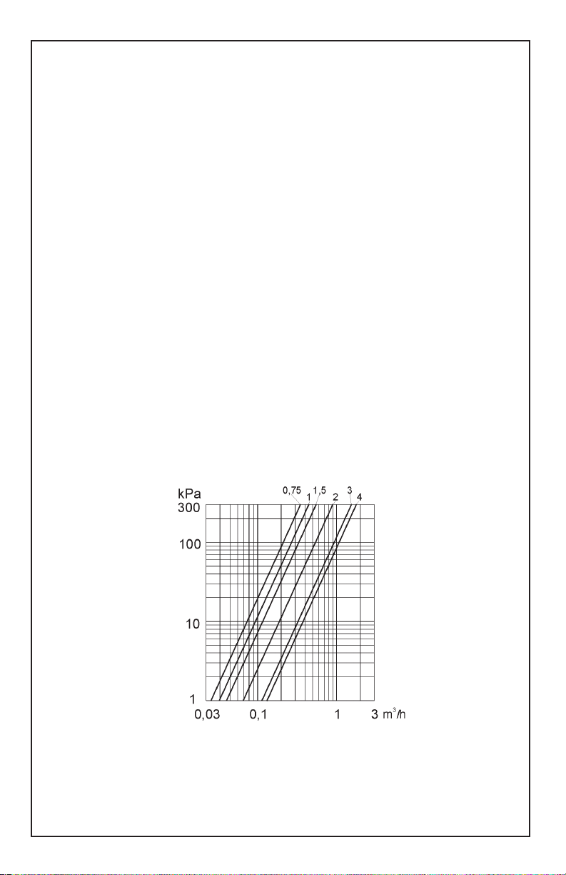
Presetting knob for control valve 5
Application
• With this knob you can adjust the resistance value of the MOH2 control
valve.
• This controls the maximum amount of water which enters the MOH2
from the boiler loop with the control valve fully open.
• Use this knob to adapt the MOH2 to the heating system and to optimize
the control characteristics.
• It is especially important to adjust the presetting knob correctly if several
MOH2 stations are attached to one boiler loop. This ensures that all
stations will get a sufficient amount of water from the boiler loop.
Setting
• Use the diagram below for setting the presetting knob correctly. It shows
the differential pressure vs. flow rate for the boiler side of the MOH2
including control valve.
• First, determine the amount of boiler water needed during peak heat
demand.
Using this amount of water and the differential pressure available during
peak heat demand, you find the appropriate setting of the knob in the
diagram.
• Close the presetting knob completely [turn right until full stop]. Open
counter clockwise the number of turns shown in the diagram.
www.lainginc.com
Resistance curve presetting knob
13
Page 14

Installation and operation manual MOH2
Filling the system
Preparation
• Close the ball valves 10 and 11 at the boiler feed and return of the
MOH2 mixing module.
• Open the feed valve and return flow adjuster of the left most floor heating
loop directly adjacent to the fill- and drain valves 12 and 13
• Close the feed valves and return flow adjusters of all other floor heating
loops.
Filling of the boiler loop
• Fill the boiler loop as usual. No special precautions are necessary.
Filling of floor heating loops
• Connect the fill hose to the upper fill valve 12.
• Connect the drain hose to the lower drain valve 13.
• In this way, the built in check valve 7 at the floor heating feed side will
close and the water will run through the floor heating loops.
• Flush the first loop until it is completely free of air.
• Close the first loop and open the next loop going from left to right.
Repeat until all loops have been flushed.
After filling
• Open the valves 10 and 11 of the boiler loop
• Open all floor heating loops
Verification of proper filling
• Shut down the heating system or set the boiler temperature to ambient
• Switch on the boiler circulator and the circulator of the mixing module
• Open the control valve. Remove the valve cover to do so if necessary.
• You should hear very few air noises, which should get less over time.
• If the air noises do not decrease but persist or even increase, is
necessary to repeat the air purging as described above.
Pressure test
Preparation
• Open all feed valves of the floor heating loops.
• Close the ball valves 10 and 11 [which connect the module to the boiler
loop]
• Close all return flow adjusters of the floor heating loops.
• Connect the pressure hose to the fill valve 12.
14
www.lainginc.com
Page 15

Installation and operation manual MOH2
Pressure test
• Pressurize the pressure hose
• Now all heating loops including the compression fittings are being
pressure tested.
Start-up
Preconditions:
•The system boiler loop must be filled properly.
• The floor heating system must be filled properly
• A suitable control for the MOH2 module must be in place. Caution:
operation without a suitable control can result in overheating of the floor
heating system.
• The bypass valve must be set in accordance with the control method
selected and the system parameters.
• The presetting knob must be set correctly for the system.
• The heating loops must be open.
• The connection to the boiler loop [ball valves 10 and 11] must be open.
Start-up
• If the preconditions are met, the system can be started up.
• First switch on the control.
• The first heating up of a floor heating system can take a long time since
the floor can absorb a lot of heat. Additionally, in new construction, the
high humidity in the slab can delay the heat up process.
www.lainginc.com
15
Page 16

Installation and operation manual MOH2
Technical data
Maximum system pressure 145 PSI (10 bar )
Circulator see diagram
Floor heating loop
Maximum temperature 140°F (60°C)
Feed connection 1" female thread/flange for segmented
plastic manifold
Return connection...
Boiler loop
Maximum temperature 220°F (105°C)
Feed connection 3/4" female thread in ball valve
Return connection...
Heating performance of MOH2 module
• The heating performance of the MOH2 module is dependent on
- Hydraulic characteristic of the floor heating system
- Differential pressure between boiler feed and return
- Temperature difference between boiler loop and floor heating loop
• Example
- Floor heating feed temperature 50°C [120°F]
- Floor heating return temperature 42°C [108°F]
- Pressure drop in floor heating loops including manifolds 23 kPa [7.5ft]
- The pump curve yields for this differential pressure a flow rate of the
integrated circulator of 1.7 m3/h [7.48 US GPM].
- This means that the MOH2 module can distribute 15.8 kW. in the
floor heating system.
- With an assumed delta T in the boiler loop of 25 K. [45°F], the boiler
loop needs to furnish 0.5 m3/h [2.2 US GPM] at peak heat demand
- Since the boiler return temperature is equal to or larger than the
floor heating return temperature, the minimum boiler feed temperature
at peak heat demand is 67°C [150°F]
- The diagram for the presetting knob which adjusts the boiler side
differential pressure shows that for this flow rate, the differential
pressure in the boiler loop needs to be at least 20 kPa [6.6 ft].
16
www.lainginc.com
Page 17

Installation and operation manual MOH2
Pump curve
The pump curve shows the hydraulic performance available at the
manifold connections
14
12
10
8
6
4
2
Pump head [ft]
0
0 2 4 6 8 10 12 14
Flow rate [US GPM]
www.lainginc.com
17
Page 18

Installation and operation manual MOH2
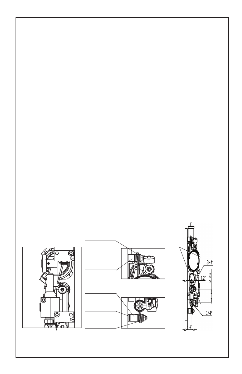
Dimensions
Side view for angled installation Side view for paralell installation
18
www.lainginc.com
Page 19

Installation and operation manual MOH2
Changing out the circulator
Preparation
• Caution: only a properly licensed electrician should disconnect and
reconnect the circulator.
• Remove electrical power even if you only want to clean the circulator
and not remove it.
• Close the ball valves 10 and 11 on the boiler feed and return side
• Connect the drain hose to the lower drain valve 13. In this way, the
check valve 7 will close automatically and the manifold will not drain
completely.
• Make sure that the drain hose can drain below the level of the circulator
pump
Draining of the water
• Open the drain valve 13
• When all water has drained, loosen the upper pump mounting screw to
allow air entry.
• Drain an additional 1/4 liter.
• Now the water should be below the level of the pump
Changing the circulator
• Remove both pump mounting screws.
• Take care when removing the pump since the rotor is only sitting loosely
on the ceramic ball and can fall out. Tilt the wiring end downward slightly
to prevent this.
• After removing the drive unit you can remove the rotor and clean it if
necessary.
• If the rotor have scratches in the lower part, the bearing has run out and
a new drive unit needs to be installed
• Have a properly licensed electrician disconnect the old circulator and
reconnect a new one.
• Before reassembly, carefully clean the seal ring and the housing.
• Reinsert the drive unit and tighten the two pump mounting screws
Restarting the system
• Refill unit by connecting the drain hose to a faucet. The air will bleed
through the automatic air purger.
• Open the valves on the boiler feed and return side
• Re-energize the unit
• The unit should be ready for operation
www.lainginc.com
19
Page 20

Installation and operation manual MOH2
Troubleshooting
• If you use Laing controls, you’ll get error messages for typical errors.
You find the explanation of these error messages in the manual of the
control. In most cases, this will answer your question.
Step-down control doesn’t work:
• The sensors for boiler feed temperature and floor heating feed temperature
have not been connected properly.
Connect sensors according to the appropriate instruction.
• The bypass valve is closed or opened
insufficiently. Open the bypass valve
according to the appropriate instruction.
The feed temperature is oscillating significantly:
• The presetting valve is opened too far,
therefore too much boiler water is entering the floor heating loop. Adjust the
presetting valve according to the appropriate instruction.
• If the heating load is very small, for
example, if only one short loop is open,
an oscillation of the feed temperature is
normal.
The pump is not running: • Possibly the over temperature protec-
tion has tripped and shut off the pump.
• If not, the pump may be clogged by dirt.
Remove the circulator to inspect it.
Heating performance is insufficient:
• The presetting knob is turned in too far
• The bypass valve is opened too far
• The system is just being put into
service, in which case it may take
longer to heat the floor for the first time.
As long as the floor heating return
temperature is still cold, the feed
temperature also cannot increase
independently since most of the feed
water comes from the floor heating
return and only a small portion is boiler
water.
20
www.lainginc.com
Page 21

Installation and operation manual MOH2
www.lainginc.com
21
Page 22

03282006 Subject to change without notice
Phone: (619) 575-7466 · Fax: (619) 575-2739 · E-Mail technicalsupport@lainginc.com
Laing Thermotech, Inc. · 830 Bay Blvd. Suite #101 · Chula Vista, CA 91911
or customerservice@lainginc.com · Internet: www.lainginc.com
 Loading...