

Page 1
Series 150, 150S, 157, 157S
!
Bellows Replacement
INSTRUCTION MANUAL
MM-711B
Series 150S
Series 150
WARNING
CAUTION
WARNING
• Before using product, read and understand instructions.
• Save these instructions for future reference.
• All work must be performed by qualified personnel trained in the proper application,
installation, and maintenance of plumbing, steam, and electrical equipment and/or systems
in accordance with all applicable codes and ordinances.
• To prevent electrical shock, turn off the electrical power before making electrical
connections.
• To prevent serious burns release all pressure and let boiler cool down to 80˚F (27˚C).
• Drain water level down below the float bowl chamber before taking the head mechanism
out of the body.
Failure to follow this warning could cause property damage, personal injury or death.
Page 2

C
E
D
A
L
F
J
K
B
M
H
D
H
G
J
K
B
C
J
F
A
G
D
P
N
R
E
OFF
ON
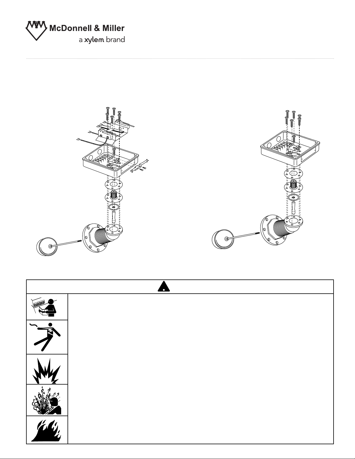
STEP 1 - Preparation
E
D
A
F
C
B
a. To prevent electrical shock turn off all electrical
power to the boiler.
CAUTION: There may be more than one source
of power to the boiler.
b. Release all pressure from the boiler and let it cool down to 80˚F (27˚C). Drain the water level
down below the float chamber.
c. Remove the four screws that hold the cover on the
switch housing (A) and remove the cover. Mark all
electrical supply wires so they can be returned to
the proper terminals. Remove the wires and conduit
connections from switch housing (A).
d. Remove eight hex head bolts holding head
mechanism (B) to float chamber. Carefully remove
head mechanism (B) from float chamber and place
in a vise.
e. Holding float (C) firmly, unscrew Allen
®
or Torx
®
fastener (D). (Units with date codes of E99 or earlier
will have Allen
F99 or later will have Torx
®
head fasteners. Those with codes of
®
fastener). Unscrew float
and float rod (C). For snap switch units see Step 3a.
For mercury switch units remove the two mercury
switches. Remove six (6) Allen
®
or Torx®screws (E).
f. Remove switch housing (A) from head casting (B).
The bellows assembly (F) may stick to the switch
housing (A). Remove bellow assembly (F) and
clean gasket surfaces on both head casting (B) and
switch housing (A).
Four Cover
Screws
A
B
Eight Hex
Head Bolts
2
Page 3
3
C
E
D
A
L
F
J
K
B
M
H
D
H
G
J
K
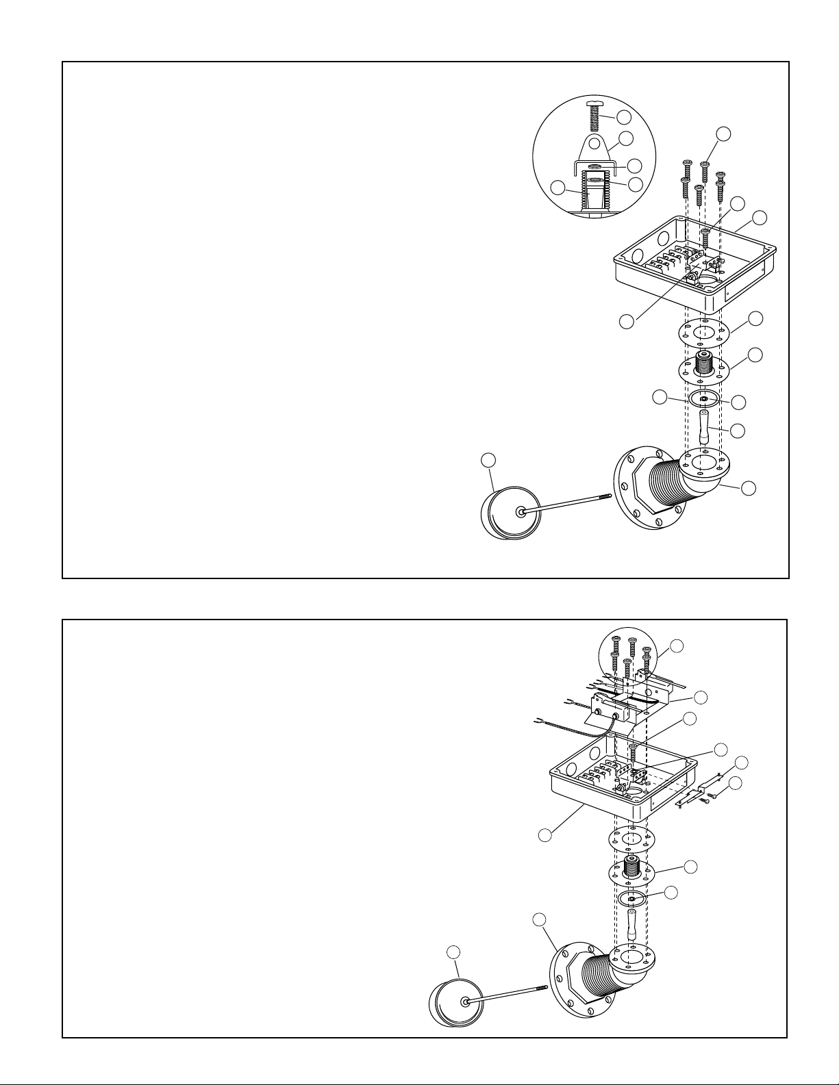
STEP 2 - Changing the Bellows for Mercury Switch Units (For Snap Switch See STEP 3)
c. Make sure tapped hole on float arm (K) is facing the
correct way, so the float and float rod (C) can be
screwed into it when bellows assembly is assembled
on the head casting. Place gasket (M) on casting (B).
Center the gasket and place the bellows assembly (F)
and switch housing (A) on head casting (B). Insert and
tighten six (6) Torx
®
screws (E) to 125 in. lbs. (14 N•m).
d. Screw float and float rod (C) into float arm (K) and
hand tighten. Center the float rod in the float rod
guide (not shown) and tighten Torx screw (D) to
125 in. lbs. (14 N•m). Make sure you hold the float
in place while tightening screw (D). Move the float
up and down, making sure there is no binding and
that the float rod is still centered.
b. Take the new bellow assembly (F) and disassemble it
noting the order of the parts. Put sealing washer (J) on
top of float arm (K) and insert into inside of bellows (F).
Place gasket (L) over bellows (F). Insert this assembly
into switch housing (A) and bracket (H). If the screw (D)
was an Allen
®
screw, the spacer washer (G) will have to
be put in the top hole of bracket (H). Take Torx
®
screw (D)
(furnished) and insert it into hole on top of bracket (H) and
spacer washer (G) (if needed) and screw into float arm (K).
Hand tighten only.
a. NOTE: On units that have Allen
®
head screws they should
be replaced with Torx
®
screws (furnished).
B
C
J
F
A
G
D
P
N
R
E
Step 3 - Changing the Bellows for Snap Switch Units
a. Clean out sealant and remove two (2) screws (N)
and bracket (P). Remove (6) Allen
®
or Torx®screws
(E). Remove switch housing (A) from head casting (B).
The switch bracket (R) will come out with the switch
housing (A). The bellows assembly (F) may stick to
the switch housing (A). Remove bellow assembly (F)
and clean gasket surfaces on both head casting (B)
and switch housing (A).
Page 4

WARNING
CAUTION
!
Step 3 - Changing the Bellows for Snap Switch Units cont’d)
b. NOTE: On units that have Allen®head screws they
®
will be replaced with Torx
c. Take the new bellows assembly (F) and disassemble
it noting the order of parts. Put sealing washer (J)
on top of float arm (K) and insert into inside of
bellows (F). Place gasket (L) over bellows (F).
Insert this assembly into switch housing (A) and
bracket (H). If the screw (D) was an Allen
the spacer washer (G) will have to be put in the top
hole of bracket (H). Take Torx
(furnished) and insert it into hole on top of bracket
(H) and spacer washer (G) (if needed) and screw
into float arm (K). Hand tighten only.
d. Make sure the tapped hole on float arm (K) is
facing the correct way, so the float and float
rod (C) can be screwed into it when bellows
assembly is assembled on the head casting.
Place gasket (M) on head casting (B). Center the
gasket and place the bellows assembly (F) and
the switch housing (A) on head casting (B). Insert
and tighten the six (6) Torx
lbs. (14N•m). Make sure that two (2) of the screws
capture the switch bracket (R).
e. Screw float and float rod (C) into float arm (K)
and hand tighten. Center the float rod in the float
rod guide (not shown) and tighten Torx
to 125 in. lbs. (14N•m). Make sure you hold the
float in place while tightening screw (D). Move the
float up and down, making sure there is no binding
and that the float rod is still centered. Install bracket
(P) using screws (N), tighten to 40 in. lbs.
(4.5 N•m).
screws (furnished).
®
screw,
®
screw (D)
®
screws (E) to 125 in.
®
screw (D)
K
C
D
H
G
J
M
E
R
D
H
A
P
L
F
J
K
B
N
STEP 4 - Assembling the Head to the Body and Test for Proper Operation
a. Clean the gasket surface on head casting (B) and the body casting. Using a new gasket (furnished)
mount the head mechanism to the body casting. Tighten the eight (8) bolts to 18 ft. lbs. (24N•m).
Reattach conduit connectors and connect wires to the proper terminals. Turn on electrical power to
the boiler.
b. Run the unit through several cycles of operation, noting the operating points. On the snap
switch controls it may be necessary to readjust the switches. If this is necessary follow the
enclosed instructions. (See attached for reference only, MM-235).
Xylem Inc.
8200 N. Austin Avenue
Morton Grove, Illinois 60053
Phone: (847) 966-3700
Fax: (847) 965-8379
www.xyleminc.com/brands/mcdonnellmiller
McDonnell & Miller is a trademark of Xylem Inc. or one of its subsidiaries.
© 2012 Xylem Inc. MM-711B April 2012 Part No. 246765
 Loading...