

Page 1
Replacement Cam CO-106 (302900)
For Combination Mechanical
Water Feeder/Low Water Cut-Off
Series 47-2
51-2
51-S-2
53-2
247-2
For Low Water Cut-Off Series 63
WARNING
INSTRUCTION MANUAL
MM-710B
CAUTION
WARNING
• Before using this product read and understand instructions.
• Save these instructions for future reference.
• All work must be performed by qualified personnel trained in the proper application, installation, and maintenance of plumbing, steam, and electrical equipment and/or systems in
accordance with all applicable codes and ordinances.
• To prevent electrical shock, turn off the electrical power before making electrical connections.
• The low water cut-off switch must be installed in series with all other limit and operating
controls installed on the boiler. After installation, check for proper operation of all of the
limit and operating controls before leaving the site.
Failure to follow this warning could cause property damage, personal injury or death.
STEP 1 - Preparation
a. Check to see which type of float arm is on the control.
Select the replacement cam that is the same as the one
being replaced.
STEP 2 - Installation
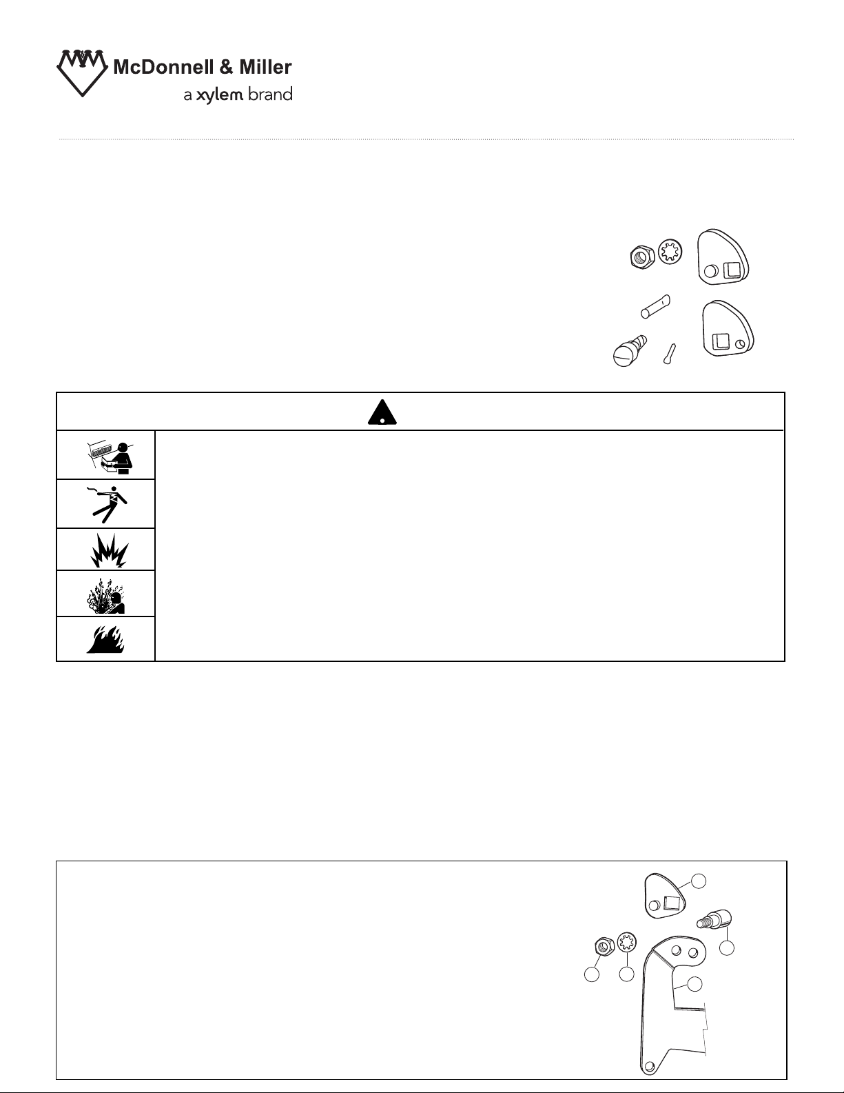
For Combination Water Feeder/Low Water Cut-Off with a one-piece float arm (manufactured after 9/98)
For all except Series 63:
b. Establish boiler water level at 5/8” to 1 1/8” (16-
29mm) below the low water cut-off casting line,
depending on the water feeder.
For Series 63:
c. Establish boiler water level at the low water cut-off
casting line.
a. Remove the four (4) screws of the No. 2 switch and lift
off the entire mechanism.
b. Remove nut (B), lock washer (C), and eccentric screw
(A). Then pull the old cam (D) straight out from float
arm (E) and discard it.
c. Making sure that the dimple on the cam fits in the hole
of the float arm (E), set the new cam in place. Reinstall
the eccentric screw (A), lock washer (C), and nut (B),
but do not tighten.
Proceed to step d.
C
B
D
A
E
Page 2
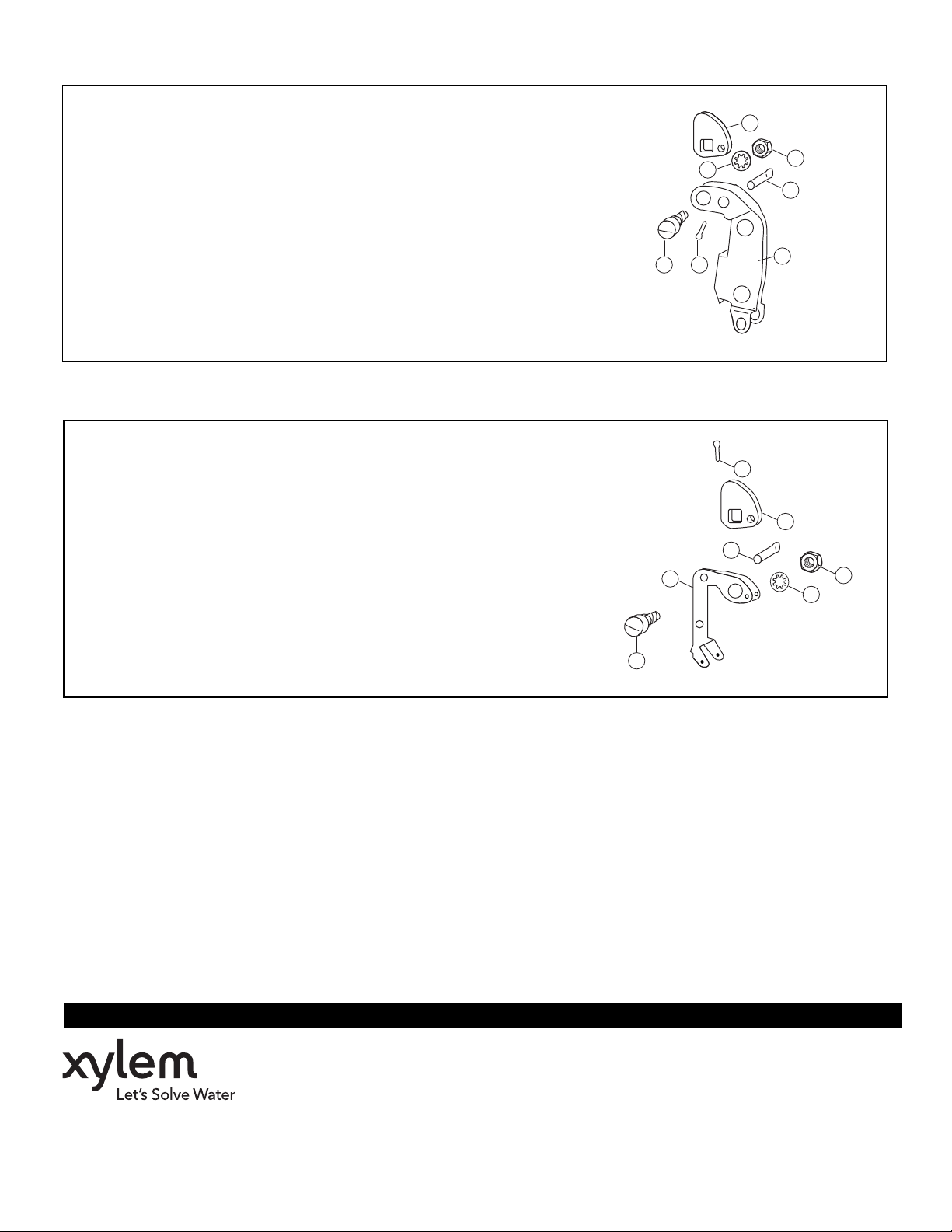
For Combination Water Feeder/Low Water Cut-Off with a two-piece float arm (manufactured before 9/98)
a. Remove the four (4) screws of the No. 2 switch and lift
off the entire mechanism.
F
b. Remove nut (B), lock washer (C), and eccentric screw
(A), cotter pin (D), and brass pin (E). Then remove the
old cam (F) from the two-piece float arm (G) and discard it.
c. Set new cam (F) in place. Install new brass pin (E),
securing it with a new cotter pin (D). Reinstall the
eccentric screw (A), lock washer (C), and nut (B), but
do not tighten.
Proceed to step d.
For Low Water Cut-Off Series 63
a. Remove the four (4) screws of the No. 2 switch and lift
off the entire mechanism.
b. Remove nut (B), lock washer (C), and eccentric screw
(A), cotter pin (D), and brass pin (E). Then remove the
old cam (F) from the float arm (G) and discard it.
c. Set new cam (F) in place. Install new brass pin (E),
securing it with a new cotter pin (D). Reinstall the
eccentric screw (A), lock washer (C), and nut (B), but
do not tighten.
C
A
D
D
E
G
B
E
G
F
B
C
Proceed to step d.
A
d. Using a flathead screwdriver, turn eccentric screw (A) until cam (D) is set in lowest possible position.
e. Reinstall the No. 2 switch and tighten the four (4) screws.
f. Slowly, turn eccentric screw (A) raising the cam (D) until the switch clicks, opening the common and
normally closed contacts. Hold eccentric screw (A) in position and tighten nut (B) on the opposite end.
STEP 3 - Testing
a. Check to see that the burner turns on and off, by raising and lowering the water level in the boiler.
b. Make sure there is travel in the float arm after the burner goes on and off.
c. Repeat test several times.
INSTALLATION COMPLETE
Xylem Inc.
8200 N. Austin Avenue
Morton Grove, Illinois 60053
Phone: (847) 966-3700
Fax: (847) 965-8379
www.xyleminc.com/brands/mcdonnellmiller
McDonnell & Miller is a trademark of Xylem Inc. or one of its subsidiaries.
© 2012 Xylem Inc. MM-710B August 2012 Part No. 246777
 Loading...