

Page 1
Model AS-5S
Ambient Remote Sensor
For LPC-2000 General Purpose
Level Control
OPERATION
INSTRUCTION MANUAL
MM-107B
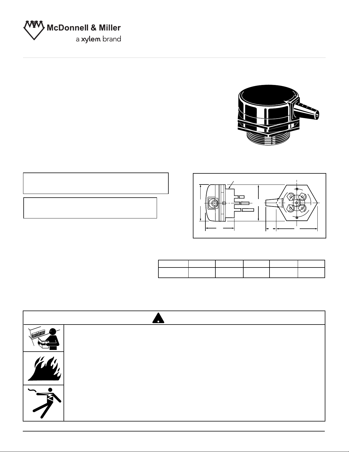
Model AS-5S
IMPORTANT: This is a NEMA 1 enclosure,
which is not designed for outdoor applications.
IMPORTANT: Do not use on high voltage.
Use only with Series LPC-2000 control unit.
Maximum Pressure: 0 psi.
Maximum Temperature: 120˚F (49˚C)
Dimensions, in. (mm)
ISO7-RP2 3
!
TION
AU
C
G
NIN
R
A
W
A
E4
E1
E
D
A BCD E F
5
⁄8 (92) 11⁄32 (26) 23⁄8 (60) 35⁄32 (80) 35⁄32 (80)
B
C
E5
E2
E3
F
WARNING
• Before using this product read and understand instructions.
• Save these instructions for future reference.
• All work must be performed by qualified personnel trained in the proper application, installation, and maintenance of plumbing steam, hot water, and electrical equipment and/or
systems in accordance with all applicable codes and ordinances.
• To prevent electrical shock, turn off the electrical power before making electrical connections.
Failure to follow this warning could cause property damage, personal injury or death.
Page 2
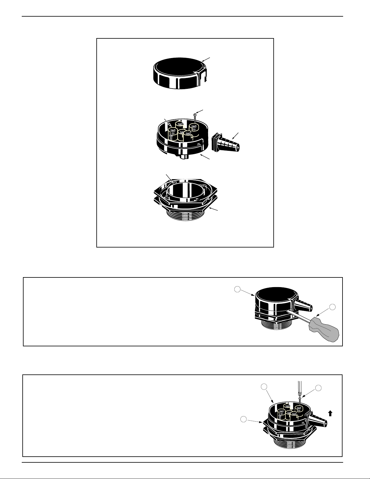
Exploded View
B
A
Cover
Tightening screw mounting holes
Wiring terminal
screw
Tightening screw
Case
Base
Nozzle
E
C
x 2
D
Disassemble the Sensor to Install Probes
a. Remove the case cover (A).
b. Insert a flat bladed screwdriver (B) into one of
the two slots on the cover and twist the
screwdriver. Repeat this step on the other slot.
Remove the case (C) from the base (D) by
loosening the two screws (E) and lift off.
2
Page 3

Mount Base to Tank
D
J
G
F
H
L
J
H
G
K
F
G
E
C
x 2
D
Install base (D) on tank and screw hand tight.
NOTE: The base threads are international standard
ISO7-RP2. While the international standard is not
identical to the standard National Pipe Thread
(NPT) or standard straight 2 inch pipe thread, it is
similar. As such a connection with 3 or 4 threads of
the base can be made in a 2 inch NPT pipe.
Connect Electrodes to Case
If using more than one electrode, allow space for maximum distance
between them.
a. Unscrew the case set screw (F). Back it out far enough to allow
for electrode insertion.
b. Thread the lock nut (G) onto the electrode (H) and place the
spring washer (J) on top of the nut.
c. Screw this assembly into the case until it stops. Tighten the lock
nut (G) until the spring washer (J) becomes flat. Tighten the set screw
(F) to 11 in. lbs. (12 cm kg.). Repeat step for each electrode.
If the required length of the electrode is greater than 39" (1 meter)
a. Use an electrode separator (K) (not included) at each joint
when joining two electrodes together. This prevents the
electrodes from touching each other and false signaling.
b. Back out the two set screws (F) far enough so that the elec-
trode (H) clears them. Install a lock nut (G) and spring washer
(J) on each electrode. Screw the two electrodes into the connecting nut (L) so that they meet in the middle. Tighten the
lock nuts (G). Tighten the two set screws (F).
Assemble Case into Base
a. Mount the case and electrode assembly (C) into the
base (D). Note that there are holes in the base to
allow the nozzle to be positioned in 90 degree
increments.
b. Align the holes and tighten the two screws (E) holding
the base and case together.
3
Page 4
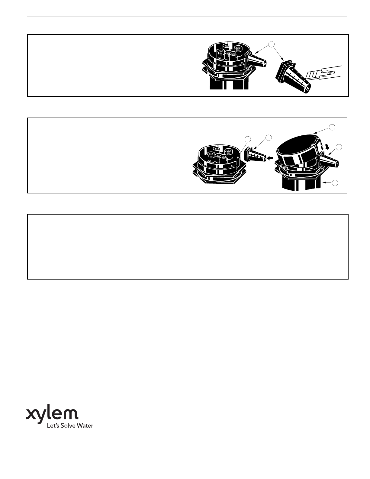
Size the Nozzle
a. Determine the opening size needed to
accomodate the number and size of
wires you have.
b. Cut the nozzle (M) as necessary.
Install Wires and Cover
a. Pull the wire(s) through the nozzle (M)
and place the nozzle into the slot (N) on
the case.
b. Attach the wire(s) to the appropriate probe
terminal. Be sure to insert the wire(s) under
the wire clamp and tighten.
c. Snap the cover (A) onto the case (C).
Troubleshooting
M
Knife
A
N
M
M
C
If the liquid level control fails to operate as required, perform the following diagnostic checks:
1. Re-check all wiring to ensure proper connections as specified in these instructions.
2. Check to be sure that the fluid level is contacting the probes to initiate the desired level-sensing functions.
3. If the tank or vessel is conductive, securely connect a wire to it. Connect the other end of this wire to the
ground probe terminal on the Series LPC-2000. If the vessel is not conductive or if you are unable to do
this, use a ground probe. It must be longer than any of the other probes.
MAINTENANCE
SCHEDULE:
• Inspect probe annually for scale build-up and
clean if necessary. Make certain there is no
scale or build-up on the probe or its insulator.
• Replace probe every 10 years. More frequent
replacement of the probe is required if it is used
in locales where significant water treatment is
required, where more frequent cleaning is necessary, or in applications with high make-up
water requirements.
• Replace the control unit every 15 years.
Xylem Inc.
8200 N. Austin Avenue
Morton Grove, Illinois 60053
Phone: (847) 966-3700
Fax: (847) 965-8379
www.xyleminc.com/brands/mcdonnellmiller
McDonnell & Miller is a trademark of Xylem Inc. or one of its subsidiaries.
© 2012 Xylem Inc. MM-107B August 2012 Part No. 210386
 Loading...