

Page 1
Manual
Manual
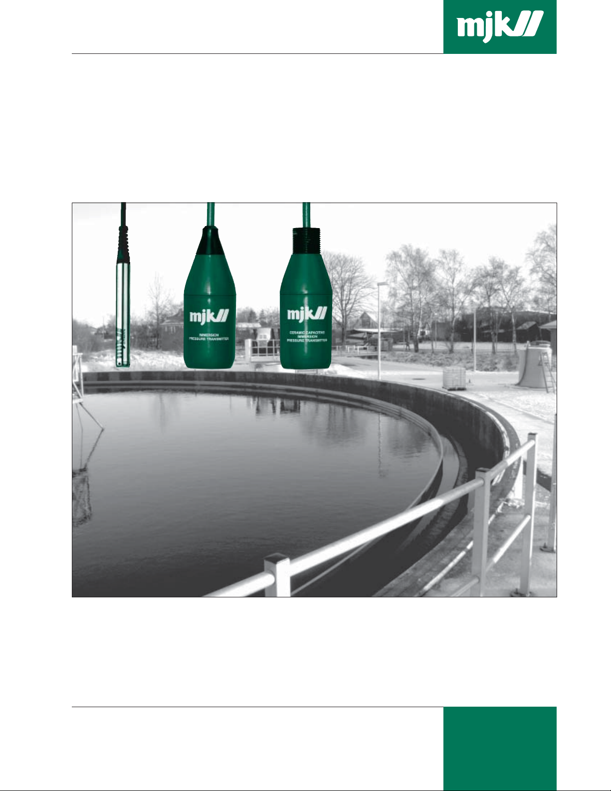
MJK 1100 / 2100 / 3100
Submersible Hydrostatic Level Transmitters
M275US0205
As our products are developed continuously we reserve the right to make any
change in the dimensions and the specifications.
MJK Automation A/S
Byageren 7
DK-2850 Nærum
Denmark
Tel.: (+45) 45 56 06 56
Fax: (+45) 45 56 06 46
mjk@mjk.com
www.mjk.com
Page 2

Manual
General
Safety instructions 1: Read this manual carefully.
Product identification and
pressure ranges
Model 1100
Nominal pressure
range 0 - 10 ft,
0 - 30 ft, 0 - 100 ft.
Other ranges
available; see data
sheet.
Level measuring with a pressure transmitter
is done by immersing a transmitter in the
liquid. The transmitter measures the
hydrostatic pressure and generates a
current signal that is proportional with the
hydrostatic pressure and thus proportional
with the liquid level.
2: Be aware of the environment on the
installation site. Wear neseccary protective equipment and follow all current
safety regulations.
It is very important for the overall measuring
accuracy that the pressure transmitter has
the correct pressure range.
Check that the item(s) delivered corresponds
to the ordered item(s) by means of the
information on the label on the packing:
Model 2100
Nominal pressure
range 0 - 10 ft,
0 - 30 ft, 0 - 100 ft.
Other ranges
available; see data
sheet.
The MJK Submersible Hydrostatic Level
Transmitters are all designed to generate
a 2-wire (passive) 4 - 20 mA signal with a
10 - 30 V DC supply.
3: MJK Pressure Transmitters must not be
used in explosion hazarduous areas.
4: MJK Pressure Transmitters must not be
submerged into flammable liquids.
On the model 1100 transmitter, all the
standard pressure ranges together with the
corresponding order numbers are printed on
a label on the transmitter housing. The
pressure range can be determined by
comparing the order number impressed in
the steel housing (together with the serial
number) with the numbers on the label.
Model 3100
Nominal pressure
range 0 - 1 ft,
0 - 3 ft, 0 - 10 ft.
Other ranges
available; see data
sheet.
M275US0205
Shown below is the label for a model 1100
pressure transmitter, range 0-10 ft:
➀➀
➀
➀➀
➁➁
➁
➁➁
➂➂
➂
➂➂
➃➃
➃
➃➃
➀➀
➀ Item number
➀➀
➁➁
➁ Item description
➁➁
The same information plus cable length is
printed on a similar label tagged onto the
transmitter cable.
➂➂
➂ Pressure range
➂➂
➃➃
➃ Serial number
➃➃
On model 2100 and 3100 transmitters, the
actual pressure range is ticked off on the
label on the housing.
For all verstions the pressure range can be
determined through the serial number.
MJK Automation A/S
Byageren 7
DK-2850 Nærum
Denmark
Tel.: (+45) 45 56 06 56
Fax: (+45) 45 56 06 46
mjk@mjk.com
www.mjk.com
Page 3

Manual
Mechanical mounting,
Model 1100
Model 2100
1: Mount a suitable hook over the desired
measuring location. Note the weight of
the cable.
2: Remove the inner conical sleeve from
the cable fitting and pull the cable
through the outer part. Open the inner
sleeve and fit it around the cable at the
desired fixation point and press the
inner sleeve into place in the outer part.
Secure the cable fitting by pulling the
cable downwards.
3: Lower the pressure transmitter into the
wellpipe. Take care not to hit the
bottom hard since it may damage the
transmitter!
1: Mount a suitable hook over the desired
measuring location. Note the weight of
the cable.
2: Mount the cable fitting onto the cable.
Open the fitting by sliding the two plastic
jaws upwards, place the cable between
the jaws and slide the jaws downwards
until the cable locks. Secure the cable
fitting by pulling the cable downwards.
3: Lower the pressure transmitter into the liquid.
Take care not to hit the bottom hard since it
may damage the transmitter!
4: If the transmitter is to be used in a
wetwell or other locations with
turbulence or other disturbance, it is
advisable to install a pipe (min. nominal
diameter = 3 in) to protect the transmitter from bumping into the wall or
other components. It is very important
that minimum 1 in of the pressure
transmitter is not being covered by
the pipe!
Cable fitting
Cable fitting
Protective pipe
Min. nominal
dimension = 3 in.
Min. 1 - 2 in !
Model 1100
Model 2100
Model 3100
M275US0205
1: Mount the pressure transmitter onto a 1
in pipe (1” NPT thread) and mount the
pipe firmly at the desired measuring
location.
2: Lower the pressure transmitter into the
liquid. Take care not to hit the bottom
hard since it may damage the transmitter!
1 in NPT thread
Model 3100
MJK Automation A/S
Byageren 7
DK-2850 Nærum
Denmark
Tel.: (+45) 45 56 06 56
Fax: (+45) 45 56 06 46
mjk@mjk.com
www.mjk.com
Page 4

Manual
Electrical mounting The pressure transmitters are delivered with
39 ft of cable as standard (except 209940
and 209960: 120 ft).
The cable can be lengthened with any type
of cable using connection box 202922.
Although the measuring signal is not sensitive to electrical noise, we recommend
the use of a screened cable.
Ensure that no moisture can enter the
pressure compensation tube inside the cable.
The length of the cable is only limited by
the total resistance (A) of the cable wires +
the input impedance of the analog input on
the MJK 704, MJK 713, PLC etc. (typically 10
to 100 Ω) and the available supply voltage
(B) (typically 24 V DC).
Example:
The nominal resistance for 1 wire in a
transmitter cable is 0.011
ΩΩ
Ω/ft. A standard
ΩΩ
39 ft cable will therefore add 2 x 0.011 x 39 =
Designation of wires,
cutting & stripping the
cable
The factory delivered cable has the wires
marked with the numbers 1 - 2 - 3 as to
the table to the right. If the cable needs to
be cutted and stripped, the shield should
be connected as the no. 3 wire.
Do NOT connect any of the colored programming wires as it may damage the transmitter. The programming wires should be cut off
in different lengths to prevent them from short
circuit. Take care not to block or squeeze
the air pressure compensation tube
➃➃
➃.
➃➃
ΩΩ
0.86
Ω to the loop resistance. If the analog
ΩΩ
input has an impedance of 50 Ω, the total
resistance will be approx. 51
ΩΩ
Ω.
ΩΩ
According to the diagram below, approx.
12 V DC will be sufficient.
Necessary supply voltage in relation to
the total loop resistance.
]
Ω
Total loop resistance [
(A)
(B) Supply voltage [V DC]
Wire designation:
1: Positive (+) wire
2: Negative (-) wire
3: Shield
(NOT signal
ground!)
4: Air pressure
compensation
tube
5: Programming
wires
➃➂
➁
➀
Factory delivery. Cutted and stripped.
➁
➃
➀
➄
➂
Cable connection
M275US0205
Analog input on 704, PLC etc.
Power
supply
(10 - 30
V DC)
Analog
input
Shield
➂
(NOT signal
ground!)
Positive (+)
➀
wire
➀
➁
Negative (-)
wire
MJK Connection Box (NEMA 4X) with
vent plug, order no. 202922.
➀➁➂➀➁➂
To ULC,
PLC etc.
MJK type 531 Field Indicator, order no.
200126 (option, replaces lid for connection
box). See separate data sheet.
From pressure transmitter
MJK Automation A/S
Byageren 7
DK-2850 Nærum
Denmark
Tel.: (+45) 45 56 06 56
Fax: (+45) 45 56 06 46
mjk@mjk.com
www.mjk.com
 Loading...