

Page 1

ITT
Goulds Pumps
AquaBoost™ Controller
Variable Speed Pump Control
Installation, Operation &
Maintenance
Models Covered:
1AB1 – 1 HP (4.8A) – Single Phase
2AB1 – 2 HP (7A)
Residential Water Systems
3AB1 – 3 HP (10A)
Software
Goulds Pumps is a brand of ITT Residential and
Commercial Water.
www.goulds.com
Engineered for life
Page 2

INDEX
Index
System Design ................................................................................................................................3
Important Safety Instructions ........................................................................................................4
Installation Procedures ..................................................................................................................5
1) Pump / AquaBoost Installation ..................................................................................................5
2) Installation Confi guration .........................................................................................................6
3) Electrical Connections ...............................................................................................................6
4) Pump Priming ...........................................................................................................................9
5) Run Test ....................................................................................................................................9
Operator Displays ...........................................................................................................................9
• Error Signals ................................................................................................................................... 9
Appendix A – Pressure Transducer Data .........................................................................................11
Appendix B – AquaBoost Controller Drive Head Technical Data .....................................................12
Limited Warranty .......................................................................................................................... 13
2
Page 3

System Design
System Design
Note
Systems MUST be designed by qualifi ed technicians only and meet all applicable state and local
code requirements.
The following diagrams show a typical system using the AquaBoost Controller. Connection can be made directly to
a water supply or water can be drawn from a supply tank. Diagram #1 shows a typical set up for a supply tank.
Home Supply
Check Valves
Well Supply
Disconnect
Diagram 1
AquaBoost Installation
for Well Pump System
Circuit Breaker
AquaBoost Control
Tank
Gauge
Relief
Valve
To Drain
Isolation Valve
Atmospheric
Storage Tank
Unions
Check Valves
Diagram #2 shows a set-up for municipal water connection. This allows pump maintenance without main line
shut-off.
Home Supply Water Main
Check Valves
Circuit Breaker
AquaBoost Control
Disconnect
Isolation Valve
Unions
Relief
Valve
Check Valves
To Drain
Diagram 2
AquaBoost Installation
for Municipal Water
System
Tank
Gauge
A diaphragm pressure tank is used on the discharge side of the pump to maintain pressure in the line when
there is no demand. This will keep the pump from continuing to run. With the AquaBoost Controller, it is not
necessary to have a large tank for supply purposes. In selecting a tank, make sure it can withstand system pressure. The tank should have a capacity of at least 10% of the maximum pump fl ow rate in gpm. Typically, pumps
used with the AquaBoost controller use a V6P or larger Goulds Pumps Hydro-Pro
®
Tank. Pre-charge the tank to
the following:
PSI Set Pressure 15 30 45 60 75
PSI Tank Pre-charge 12 21 37 52 64
3
Page 4

Safety Instructions
Important: Read all safety information prior to installation of the
AquaBoost Controller.
Note
This is a SAFETY ALERT SYMBOL. When you see this symbol on the pump or in the manual,
look for one of the following signal words and be alert to the potential for personal injury or
property damage.
DANGER
WARNING
CAUTION
NOTICE Indicates special instructions which are very important and must be followed.
1. This manual is intended to assist in the installation, operation, and repair of the AquaBoost Controller and
must be kept with the AquaBoost Controller.
Warns of hazards that WILL cause serious personal injury, death, or major property
damage.
Warns of hazards that CAN cause serious personal injury, death, or major property
damage.
Warns of hazards that CAN cause personal injury or property damage.
Note
All operating instructions must be read, understood, and followed by the operating personnel.
Goulds Pumps accepts no liability for damages or operating disorders which are the result of
non-compliance with the operating instructions.
2. To avoid serious or fatal personnel injury or major property damage, read and follow all safety
instructions in this manual.
3. Installation and maintenance MUST be performed by properly trained and qualifi ed personnel.
4. Review all instructions and warnings prior to performing any work on the AquaBoost Controller.
5. Any safety decals MUST be left on the AquaBoost Controller unit and pump.
Note
Inspect AquaBoost Controller for any damage after unpacking from shipping crates. Report any
damage immediately to the carrier or distributor/dealer immediately.
6. In addition to instructions contained in this manual, you must meet any local safety, electrical or plumbing
codes and requirements. Installation, maintenance or repair work must only be carried out by trained,
skilled and qualifi ed personnel.
7. The AquaBoost Controller drive head must be disconnected from the main power supply before
attempting any operation in the electrical or mechanical part of the system.
Note
When in operation, the motor can be stopped, but power remains at the drive head. The motor
and pump could start unexpectedly and produce serious injury. When the Aquaboost Controller
drive head is connected to the main power supply, the inverter power supply and master control
unit are also connected to the power supply.
WARNING
Hazardous voltage
can shock, burn or
cause death.
WARNING!
FAILURE TO DISCONNECT ELECTRICAL POWER BEFORE ATTEMPTING ANY MAINTENANCE
CAN CAUSE SHOCK, BURNS OR DEATH.
4
4
Page 5
Installation Procedures
Step 1 – Pump / AquaBoost
Installation
1) Refer to the pump manual for instructions
on proper installation of the pump.
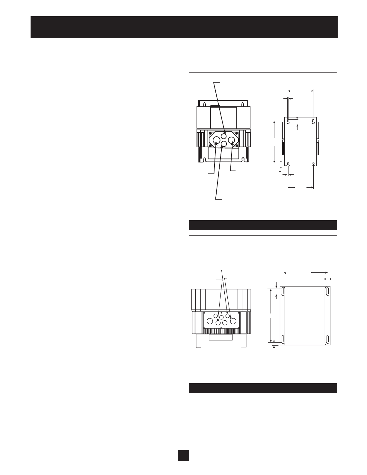
2) Mount the AquaBoost Controller on a wall in
a well-ventilated area.
1AB1
3/8” NPT
AUX. POWER
0.19
2 PLS
4.38
0.63
2 PLS
3) Pressure Transducer Installation: Locate
the pressure transducer and cable. The
threaded end of the transducer is 1/4" NPT.
Install the transducer in the tee or on the
downstream side of the check valve or foot
valve.
4) Connections in the Conduit Box: (when
using controller with other pumps) The
free end of the motor cable should now be
routed through the strain relief on the
conduit box. Connect the motor leads using
the motor nameplate as a reference. Place
the thermistor terminal in the conduit box
and fasten so that the sensor will contact
the motor shell. Note: Step 4 is completed
at the factory for complete AquaBoost pump
kits with pumps.
5) Input Power Cable Installation: The cable
has been pre-wired to the AquaBoost
Controller. Cut the loose end to length, strip
the wires and install the appropriate mating
connector or wire directly to a junction box
or distribution panel providing 208-230V,
single phase power. An all leg disconnect
switch should be provided. Follow local
electrical codes and NEC.
1/2”
NPT
INPUT
POWER
CORD
3/8” NPT
TRANSDUCER
PORT
Diagram 3
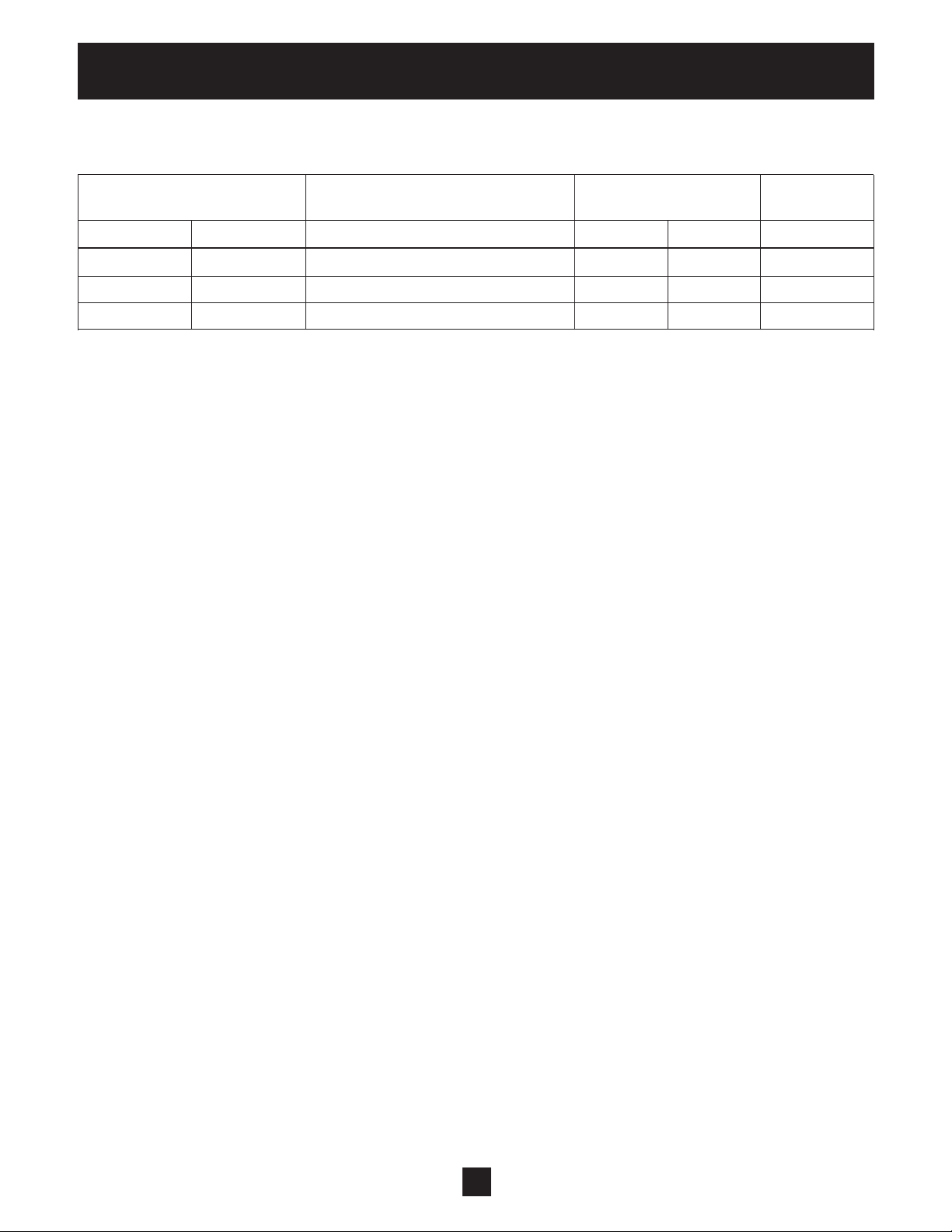
2AB1 and 3AB1
3 THRU HOLES
Ø .47
2 THRU HOLES
Ø .63
2 THRU HOLES
Ø .87
1/2”
NPT
OUTPUT
POWER
CORD
6.188
0.41
2 PLS
BACK VIEW AQUABOOST MOUNTING
0.78
7.25
0.38
0.19
2 PLS
4.38
6.00
0.25
Diagram 4
5
Page 6

Installation Procedures
Installation Confi guration
Step 2 – Electrical Connections
WARNING
WARNING!
FAILURE TO DISCONNECT AND LOCKOUT ELECTRICAL POWER AND WAIT FIVE MINUTES
FOR CAPACITOR DISCHARGE BEFORE SERVICING AQUABOOST CONTROLLER CAN CAUSE
Hazardous voltage
can shock, burn or
cause death.
SHOCK, BURNS, OR DEATH.
Note
Installation and maintenance must only be performed by properly trained and qualifi ed personnel equipped with the proper tools.
WARNING
Hazardous voltage
can shock, burn or
cause death.
WARNING!
INSTALL, GROUND AND WIRE ACCORDING TO NATIONAL, STATE AND LOCAL CODE
REQUIREMENTS.
INSTALL AN ALL LEG DISCONNECT SWITCH NEAR THE MOTOR.
DISCONNECT AND LOCKOUT ELECTRICAL POWER BEFORE INSTALLING OR SERVICING.
ELECTRICAL SUPPLY MUST MATCH PUMP’S AND AQUABOOST CONTROLLER NAMEPLATE
SPECIFICATIONS. INCORRECT VOLTAGE OR WIRING CAN CAUSE FIRE DAMAGE, AND VOIDS
WARRANTY.
MOTORS WITH AUTOMATIC THERMAL PROTECTION MAY OPEN THEIR ELECTRICAL CIRCUIT
WHEN A THERMAL OVERLOAD EXISTS. THIS CAN CAUSE THE MOTOR TO START UNEXPECTEDLY AND WITHOUT WARNING.
AquaBoost
Controller
Transducer
230V, 1Ø
Input
Thermistor
Diagram 5
230V, 3Ø
Output
Tank
Gauge
Discharge
to house
Suction
from main
6
Page 7

Installation Procedures
Installation Confi guration
Step 2 – Electrical Connections
CONTROL TERMINALS
MAIN SUPPLY
(INPUT POWER)
1Ø 230 VOLT
L
2
— L2 (BLACK)
L
1
— L
1
(BLACK)
TERMINALS
FOR RS485
MOTOR CONNECTIONS
U – BLACK
V – RED
W – BLUE
Purple Leads
Jumper
Jumper
Transducer
Connection
X2
X3
U V W
GRD #2 #1 (GREEN)
NO
12
11
10
9
8
7
6
5
4
3
2
1
4
3
2
1
CC
NC
+ 5V
GND
SIO +
SIO -
slave pump
motor thermistor
low water
external on/off R, 10 kohm, 5 volt DC
+5 V ub (red)
actual value signal 0.5-4.5 VDC, 50 ohm load resistance (white)
shield (black)
RS-485
Diagram 6
7
Page 8

Installation Procedures
Installation Confi guration
Step 2 – Electrical Connections
AquaBoost I
Connection / Wiring Diagrams
Input/Output P ower Wiring
3Ø Motor 230V
Output
GRN
RED
BLUE
BLK
GRN
GND
U
V
W
GND
L
1
AQUABOOST
CONTROLLER
N
1Ø
208-230 Volt
Supply
Terminal Block X2
1 2 3 4 5 6 7 8 9 10 11 12
BLK
Transducer
Connectors
NOTE 1: J1, J2 factory installed jumpers.
NOTE 2: Motor thermistor installed in back of ODP motor.
NOTE 3: Input supply voltage is measured phase to phase.
WHITE
RED
J1 J2
BLK
BLK
Control Wiring
PURPLE
PURPLE
Motor Thermistor
Connection
8
Page 9

Installation Procedures
Pump Priming
Refer to your pump operation manual for instructions on pump priming. Ensure suction valve is open
before start up.
Run Test
WARNING
DO NOT APPLY POWER TO THE AQUABOOST CONTROLLER OR PUMP UNTIL ELECTRICAL
CONNECTIONS HAVE BEEN REVIEWED BY A QUALIFIED ELECTRICIAN AND MEET ALL APPLICABLE NATIONAL, STATE AND LOCAL CODE REQUIREMENTS.
Instructions
1) Close discharge valve. Make sure the discharge valve is closed. Apply power to the
AquaBoost Controller.
2) Start the pump with the push button on the front plate of the AquaBoost Controller.
▼
3) Stop the pump after determining rotation by pushing the .
4) If rotation is incorrect, turn off all power to the AquaBoost, open the motor conduit box and ex
change any two lead wires. Close the conduit box and reapply power.
Change Pressure
1) Start the pump with the push button on the front plate of the AquaBoost Controller.
2) Then press the and buttons together for more than 3 seconds.
3) The LED color changes to orange.
4) Now you could change the pressure with the and buttons. The set pressure is read off a
gauge on the pump discharge.
▼
▼
▼
▼
▼
▼
WARNING
DO NOT SET THE REQUIRED PRESSURE FOR MORE THAN 80 PSI SINCE THIS CAN EXCEDE
THE CAPABILITY OF YOUR PLUMBING SYSTEM AND TANK. SERIOUS PROPERTY DAMAGE
OR PERSONAL INJURY COULD RESULT.
5) If there is no change to the setting for more than 5 seconds, the AquaBoost Controller returns to
normal operation automatically, and the new required pressure is stored.
6) The pump can only be STARTED with the button or STOPPED with the button. Both buttons
are on the front plate of the AquaBoost Controller.
▼
▼
LED description
Green Solid – Motor is not running. The unit is stopped with the button on the front plate.
Green Slow Flashing – Controller is active, but the motor has stopped.
Green Fast Flashing – Motor is running.
Red Solid – Error.
Red Flashing – Fatal error (AquaBoost Controller has to be disconnected from the power supply).
9
▼
Page 10

Operator Displays
Error Signals
The following conditions can cause a fl ashing red or solid red error light. If one of these error indications is visible, troubleshoot the system based on the following:
Low Water Remedy: Check suction pressure. If suction pressure is normal the unit restarts itself.
Overheating – Motor Possible causes: Insuffi cient cooling ambient temperature is too high, motor
overloaded. After the cause has been remedied, the malfunction has to be reset by cutting off the
power supply for > 30 seconds.
Overvoltage Possible cause: Check main supply, supply voltage too high, peak voltage due to switching heavy loads on the network. Find the cause and take countermeasures (e.g. line fi lter, RC-elements).
Disconnect the power supply for > 30 seconds.
Undervoltage Possible cause: Check main supply, faulty fuse or out of phase.
Overload Possible causes: the pump is working at a capacity signifi cantly in excess of its performance
data. Disconnect the power supply for > 30 seconds.
Overtemp. Heat Sink The thermal sensor on the heat sink indicates over temperature. Possible causes:
insuffi cient cooling, ambient temperature too high or motor overload. After remedy, cut off power for
> 30 seconds to reset.
Sensor Fault A sensor signal of below .5 VDC was received due to bad sensor, broken cable or bad
connection. After remedy cut off power for > 30 seconds to reset.
Note
The above error displays can be viewed only with the external programmer (sold separately).
This can be connected to the jack on the AquaBoost Controller for a more detailed analysis.
Contact your local distributor for more information. Goulds Pumps Part Number: 2415241.
10
Page 11

Appendix A
Pressure Transducer
The sensor of this transducer is a piezoresistive silicon pressure sensor, mounted on a tape (TAP) fl oating
freely in an oil chamber. The pressure is transferred to the sensor by a separating nickel diaphragm in
the oil chamber.
Specifi cations
Range (FS): 10 Bar (147 psi) Gauge
Over-pressure-Pmax: 300 psi
Class of protection: IP 67
Type Sealed gauge:
Signal Over Range: 0.5 - 4.5 V DC (ratiometric)
Supply: 5 VDC +/- 0.25 VDC
Supply:
+ VCC => red = supply voltage
+ Out => white analog output signal
GND => black ground
Operating Temperature: -20 - +80°C
Storage Temperature: -40 - +100°C
Material: Body Steel and Brass
Diaphragm: Nickel
1
⁄4" NPT THREAD
+ out (0.5 – 4.5 V)
GND
Pressure Transducer Plug
11
+FCC (5VDC)
Page 12
Appendix B
AquaBoost Controller Drive Head Technical Data
AquaBoost Supply Motor Voltage
Controller Protection
Type Rated output Voltage
AV 1.1 1 HP 1 x 230 V / 40-60 Hz 3 x 230 V 4.8 A 10 Ampere
AV 1.15 2 HP 1 x 230 V / 40-60 Hz 3 x 230 V 7.0 A 10 Ampere
AV 1.2 3 HP 1 x 230 V / 40-60 Hz 3 x 230 V 10.0 A 16 Ampere
Input Voltage: 1 x 230 VAC ± 10% (An input line reactor is highly recommended
for areas which experience voltage fl uctuation.)
Output Voltage: 3 x 230 Volt AC
Max. Frequency: 40 – 60 Hz – selectable
Min. Frequency: 0 - f-max
Electrical Effi ciency: > 95%
Protection against: Short circuit, under-voltage, overheating of the electronics (overload) and
additional protective functions via external switch (motor temperature,
low water).
A power supply fi lter is included to ensure interference immunity.
The AV Series frequency converter complies with the general EMV provisions and has been tested
according to the following standards:
• Radio Interference Suppression EN 50081 Part 2 and EN 50082 Part 2
• High Frequency Field Interference ENV 50140 and ENV 50141
• Static Electricity Discharge EN 61000-4
• Disturbance Voltage EN55011
Ambient Temperature: 5° C – 40° C
Storage Temperature: -25° C – +55° C
(+70° C during max. 24 hours)
Humidity: rH maximum 50% at 40° C, unlimited
RH maximum 90% at 20° C, maximum 30 days per year
Condensation not permitted!
Air Pollution: The air may contain dry dust as found in workshops where there is no
excessive quantity of dust due to machines. Excessive amounts of dust,
acids, corrosive gases, salts, etc. are not permitted.
Controller Enclosure: NEMA 12, IP 55
Approvals: UL, CUL, CE
Altitude: Maximum 3000 feet above sea level. Consult factory for higher altitudes.
12
Page 13

ITT
Residential Water Systems
This warranty applies to all water systems pumps manufactured by Goulds Pumps.
Any part or parts found to be defective within the warranty period shall be replaced at no charge to the dealer during the warranty period. The
warranty period shall exist for a period of twenty-four (24) months from date of installation or thirty (30) months from date of manufacture,
whichever period is shorter.
A dealer who believes that a warranty claim exists must contact the authorized Goulds Pumps distributor from whom the pump was purchased
and furnish complete details regarding the claim. The distributor is authorized to adjust any warranty claims utilizing the Goulds Pumps Customer Service Department.
The warranty excludes:
(a) Labor, transportation and related costs incurred by the dealer;
(b) Reinstallation costs of repaired equipment;
(c) Reinstallation costs of replacement equipment;
(d) Consequential damages of any kind; and,
(e) Reimbursement for loss caused by interruption of service.
For purposes of this warranty, the following terms have these defi nitions:
(1) “Distributor” means any individual, partnership, corporation, association, or other legal relationship that stands between Goulds Pumps
and the dealer in purchases, consignments or contracts for sale of the subject pumps.
(2) “Dealer” means any individual, partnership, corporation, association, or other legal relationship which engages in the business of selling
or leasing pumps to customers.
(3) “Customer” means any entity who buys or leases the subject pumps from a dealer. The “customer” may mean an individual, partnership,
corporation, limited liability company, association or other legal entity which may engage in any type of business.
GOULDS PUMPS LIMITED WARRANTY
THIS WARRANTY EXTENDS TO THE DEALER ONLY.
Goulds Pumps, AquaBoost, Hydro-Pro and the ITT Engineered Blocks
Symbol are registered trademarks and tradenames of ITT Corporation.
SPECIFICATIONS ARE SUBJECT TO CHANGE WITHOUT NOTICE.
IM112R04 January, 2007
© 2007 ITT Corporation
Engineered for life
13
Page 14

ITT
Bombas Goulds
Sistemas Residenciales de Agua
Controlador AquaBoost
Control de bomba de velocidad variable
MR
Instalación, Programación y
Funcionamiento
Modelos cubiertos:
1AB1 – 1 HP (4.8A) – monofásico
2AB1 – 2 HP (7A)
3AB1 – 3 HP (10A)
Software
Goulds Pumps es una marca de ITT Residential and
Commercial Water.
www.goulds.com
Engineered for life
14
Page 15

ÍNDICE
Índice
Diseño del sistema .......................................................................................................................16
Instrucciones importantes de seguridad .....................................................................................17
Procedimientos de instalación ..................................................................................................... 18
1) Instalación de la bomba / AquaBoost ......................................................................................18
2) Confi guración de la instalación ...............................................................................................19
3) Conexiones eléctricas .............................................................................................................20
4) Cebado de la bomba ..............................................................................................................22
5) Prueba de funcionamiento ....................................................................................................... 22
Indicaciones para el operador .....................................................................................................23
• Señales de errores ........................................................................................................................23
Apéndice A – Datos del Transductor de Presión .............................................................................24
Apéndice B – Datos técnicos de la cabeza de impulsión del controlador AquaBoost ......................25
Garantía Limitada ......................................................................................................................... 26
15
Page 16

Diseño del sistema
Diseño del sistema
Nota
Los sistemas DEBEN ser diseñados por técnicos capacitados únicamente y cumplir con todos los
requerimientos de los códigos estatales y locales correspondientes.
Los siguientes diagramas muestran un sistema típico que utiliza el controlador AquaBoost. Puede hacerse la conexión directamente a un suministro de agua o puede extraerse agua de un tanque de suministro. El diagrama #1
muestra una instalación típica de un tanque de suministro.
Suministro domiciliario Suministro de pozo
Válvulas de retención
Válvula de
aislamiento
Empalmes
Tanque de
almacena-
miento
atmosférico
Disyuntor
Diagram 1
Instalación Recomendada
de Aquaboost para Sistemas de Bombas de Pozo
Cortacircuito
Tanque
Control AquaBoost
Válvula
Manómetro
desahogo
de
Válvulas de retención
Drenaje
El diagrama #2 muestra una instalación típica para una conexión de agua municipal. Esto permite mantener la
bomba sin tener que cerrar la línea principal.
Suministro domiciliario Red de distribución del agua
Válvulas de retención
Diagram 2
Instalación Recomendada
de Aquaboost para Sistemas de Agua Municipal
Cortacircuito
Disyuntor
Tanque
Control AquaBoost
Manómetro
Válvula
desahogo
de
Drenaje
Válvula de
aislamiento
Empalmes
Válvulas de retención
Se utiliza un tanque de presión de diafragma en el lado de descarga de la bomba para mantener la presión en la
línea cuando no haya demanda. Esto evitará que la bomba continúe funcionando. Con el controlador AquaBoost,
no es necesario tener un tanque grande con fi nes de suministro. Cuando seleccione un tanque, asegúrese de que
pueda soportar la presión del sistema. El tanque debe tener una capacidad total de por lo menos el 10% de la
velocidad de fl ujo máxima de la bomba en gpm. Típicamente, las bombas utilizadas con el controlador AquaBoost
utilizan un tanque V6P o más grande Goulds Pumps Hydro-Pro. Precargue el tanque a los siguientes valores:
Presión establecida en lbs./pulg. cuadr. 15 30 45 60 75
Precarga del tanque en lbs./pulg. cuadr. 12 21 37 52 64
16
Page 17

Instrucciones de seguridad
Importante: Lea toda la información de seguridad antes de la instalación
del controlador AquaBoost.
Nota
Éste es un SÍMBOLO DE ALERTA DE SEGURIDAD. Cuando vea este símbolo en la bomba o
en el manual, busque una de las siguientes palabras de señal y esté alerta a la probabilidad
de lesiones personales o daños materiales.
PELIGRO
ADVERTENCIA
PRECAUCIÓN
AVISO Indica instrucciones especiales que son muy importantes y que se deben seguir.
1. El objetivo de este manual es ayudar en la instalación, operación y reparación del controlador AquaBoost
y debe ser mantenido con el controlador AquaBoost.
Advierte los peligros que CAUSARÁN graves lesiones personales, la muerte o daños
materiales mayores.
Advierte los peligros que PUEDEN causar graves lesiones personales, la muerte o daños
materiales mayores.
Advierte los peligros que PUEDEN causar lesiones personales o daños materiales.
Nota
El personal de operaciones debe leer, entender y seguir todas las instrucciones de operación.
Goulds Pumps no acepta ninguna responsabilidad por daños y perjuicios o problemas de
funcionamiento que sean el resultado de no cumplir con las instrucciones de operación.
2. Para evitar lesiones graves o fatales del personal o daños materiales mayores, lea y siga todas las
instrucciones de seguridad en este manual.
3. La instalación y el mantenimiento DEBEN ser realizados por personal apropiadamente capacitado y competente.
4. Revise todas las instrucciones y advertencias antes de realizar cualquier trabajo en el controlador AquaBoost.
5. No DEBE quitarse ningún rótulo de seguridad de la bomba o del controlador AquaBoost.
Nota
Inspeccione el controlador AquaBoost para determinar si está dañado después de desembalarlo del
cajón de empaque. Notifi que cualquier daño de inmediato al transportista o distribuidor/proveedor.
6. Además de las instrucciones contenidas en este manual, usted debe cumplir con todos los requerimien tos y códigos locales de seguridad, eléctricos y de instalaciones de agua. La instalación, mantenimiento o
el trabajo de reparación sólo debe ser realizado por personal capacitado, especializado y competente.
7. La cabeza de impulsión del controlador AquaBoost debe desconectarse de la fuente de alimentación
principal antes de intentar cualquier operación en la sección eléctrica o mecánica del sistema.
Nota
Cuando esté en funcionamiento, es posible detener el motor, pero la cabeza de impulsión continúa estando eléctricamente activada. El motor y la bomba podrían arrancar inesperadamente y producir lesiones graves. Cuando la
cabeza de impulsión del controlador AquaBoost está conectado a la fuente de alimentación principal, la fuente de
alimentación del inversor y la unidad de control principal también están conectadas a la fuente de alimentación.
ADVERTENCIA
Un voltaje peligroso puede
producir golpes eléctricos,
quemaduras o la muerte.
¡ADVERTENCIA!
LA FALLA DE DESCONECTAR LA CORRIENTE ELÉCTRICA ANTES DE INTENTAR CUALQUIER
MANTENIMIENTO, PUEDE CAUSAR ELECTROCHOQUE, QUEMADURAS O LA MUERTE.
17
17
Page 18

Procedimientos de instalación
Paso 1 – Instalación de la bomba / unidad AquaBoost
1) Consulte el manual de la bomba acerca de
instrucciones para la instalación apropiada
de la bomba.
2) Monte el controlador AquaBoost en la pared
en un área bien ventilada o válvula de pie.
3) Instalación del transductor de presión:
Identifi que el cable y el transductor de
presión. El extremo roscado del transductor
es NPT de 1/4 pulgada. Instale el transductor
en el perfi l en T o en el lado corriente abajo
de la válvula de retención con bombas.
4) Conexiones en la caja de conductos:
(cuando se usa el controlador con otras
bombas) El extremo libre del cable del motor
ahora debe pasarse por el protector contra
tirones en la caja de conductos. Conecte los
conductores del motor utilizando la placa de
identifi cación del mismo como referencia.
Coloque el terminal del termistor en la caja
de conductos y afi áncelo de modo que el
sensor haga contacto con el casco del motor.
Nota: El paso 4 se completa en la fábrica en
el caso de juegos completos de bombas
AquaBoost.
5) Instalación del cable de alimentación de
entrada: El cable viene preconectado al
controlador AquaBoost. Corte el extremo
suelto al largo adecuado, pele los alambrese
instale el conector o alambre correspond iente directamente a una caja de conexiones
o panel de distribución que proporcione
suministro eléctrico monofásico de 208 a
230 V. Debe proporcionarse un desconecta dor de todos los circuitos. Siga los
códigos eléctricos locales y el Código
Eléctrico de EE.UU. (NEC).
1AB1
CABLE DE
ALIMEN-
TACIÓN
DE
ENTRADA
NPT DE
1/2 PULG.
Diagrama 3
2AB1 y 3AB1
2 AGUJEROS
PASANTES
Ø .63
Diagrama 4
NPT DE 3/8” –
POTENCIA
AUX.
CABLE DE
ALIMEN-
TACIÓN
DE SALIDA
NPT DE
1/2 PULG.
ORIFICIO PARA
TRANSDUCTOR
NPT DE
3/8 PULG.
3 AGUJEROS
PASANTES
Ø .47
2 AGUJEROS
PASANTES
Ø .87
4.38
0.19
2 PLS
6.188
0.41
2 PLS
BACK VIEW AQUABOOST MOUNTING
0.78
7.25
0.38
0.19
2 PLS
4.38
0.63
2 PLS
6.00
0.25
18
Page 19

Procedimientos de instalación
Confi guración de la instalación
Paso 2 – conexiones eléctricas
ADVERTENCIA
Un voltaje peligroso puede
producir golpes eléctricos,
quemaduras o la muerte.
Nota
La instalación y el mantenimiento sólo deben ser realizados por personas apropiadamente capacitadas y competentes equipadas con las herramientas adecuadas.
ADVERTENCIA
Un voltaje peligroso puede
producir golpes eléctricos,
quemaduras o la muerte.
¡ADVERTENCIA!
LA FALLA DE DESCONECTAR Y BLOQUEAR LA CORRIENTE Y DE ESPERAR CINCO MINUTOS
PARA QUE EL CONDENSADOR SE DESCARGUE ANTES DE DAR SERVICIO AL CONTROLADOR
AQUABOOST, PUEDE CAUSAR ELECTROCHOQUE, QUEMADURAS O LA MUERTE.
¡ADVERTENCIA!
INSTALE, CONECTE A TIERRA Y CABLEE DE ACUERDO CON LOS REQUERIMIENTOS DE
LOS CÓDIGOS NACIONALES, ESTATALES Y LOCALES.
INSTALE UN DESCONECTADOR DE TODOS LOS CIRCUITOS CERCA DEL MOTOR.
DESCONECTE Y BLOQUEE LA CORRIENTE ELÉCTRICA ANTES INSTALAR O DAR SERVICIO.
LA FUENTE ELÉCTRICA DEBE CORRESPONDER CON LAS ESPECIFICACIONES DE LA PLACA DE
IDENTIFICACIÓN DE LA BOMBA Y DEL CONTROLADOR AQUABOOST. LA TENSIÓN O EL CABLEADO INCORRECTO PUEDE PRODUCIR DAÑOS DE INCENDIO Y ANULA LA GARANTÍA.
LOS MOTORES CON PROTECCIÓN TÉRMICA AUTOMÁTICA PUEDEN ABRIR SU CIRCUITO ELÉCTRICO CUANDO EXISTE UNA SOBRECARGA TÉRMICA. EL RESULTADO DE ESTO ES QUE EL MOTOR PODRÍA ARRANCAR INESPERADAMENTE Y SIN ADVERTENCIA.
Controlador
AquaBoost
Transductor
Indicador
Descarga a
la residencia
Succión
desde la
línea
principal
19
Entrada
monofásica
de 230 V
Diagrama 5
Salida trifásica
de 230 V
Termistor
Tanque
Page 20

Procedimientos de instalación
Confi guración de la instalación
Paso 2 – conexiones eléctricas
TERMINALES
PARA RS485
CONEXIONES DEL MOTOR
U – NEGRO
V – ROJO
A TIERRA #2 #1 (VERDE)
W – AZUL
U V W
TERMINALES
DE CONTROL
SUMINISTRO PRINCIPAL
(ENERGÍA DE ENTRADA)
1Ø 230 VOLTIOS
2
L
— L2 (NEGRO)
L 1
— L1 (NEGRO)
Plomos Púrpuras
Puente
Puente
Conexión
del
Transductor
Diagrama 6
X2
X3
12
11
10
9
8
7
6
5
4
3
2
1
4
3
2
1
NO
CC
NC
+ 5V
GND
SIO +
SIO -
Bomba es clava
Termistor del motor
Bajo nivel de agua
Encendido/apagado externo R, 10 kohm, 5 voltios CC
+5 V ub (rojo)
Señal valor real 0.5-4.5 VCC, 50 ohm resistencia de carga (blanco)
blindado (negro)
RS-485
20
Page 21

Procedimientos de instalación
Confi guración de la instalación
Paso 2 – conexiones eléctricas
AquaBoost I
Conexión/Diágramas Eléctricos
Cableado de la Energa de la Entrada/Salida
VERDE
ROJO
AZUL
NEGRO
Trifásica Motor 230V
Salida
VERDE
Monofásica
208-230 Voltios
Fuente
NEGRO
NEGRO
Controle El Cableado
Bloque de terminales X2
1 2 3 4 5 6 7 8 9 10 11 12
TIERRA
U
V
W
TIERRA
L
1
Regulador de
AquaBoost
N
NEGRO
Conectadores
del
Transductor
NOTA 1: J1, J2 puentes instalados fábrica.
NOTA 2: Viaje en automóvili el termistor instalado adentro detrís del motor de ODP.
NOTA 3: El voltaje de fuente de la entrada se mide fase a poner en fase.
BLANCO
ROJO
J1 J2
PÚRPURA
PÚRPURA
21
Conexión del
Termistor del Motor
Page 22

Procedimientos de instalación
Cebado de la bomba
Consulte el manual de operación de la bomba acerca de las instrucciones para cebarla. Asegure la válvula de succión esté abierto antes empiezan para arriba.
Prueba de funcionamiento
ADVERTENCIA
NO APLIQUE CORRIENTE A LA BOMBA O AL CONTROLADOR AQUABOOST HASTA QUE UN
ELECTRICISTA CAPACITADO HAYA INSPECCIONADO LAS CONEXIONES ELÉCTRICAS Y QUE
ÉSTAS CUMPLAN CON TODOS LOS REQUERIMIENTOS DE LOS CÓDIGOS NACIONALES, ESTATALES Y LOCALES CORRESPONDIENTES.
Instrucciones
1) Cierre la válvula de descarga. Asegúrese de que la válvula de descarga esté cerrada. Aplique
corriente al controlador AquaBoost.
2) Arranque la bomba con el pulsador en la placa frontal del controlador AquaBoost.
3) Detenga la bomba después de haber determinado la rotación presionando el pulsador .
4) Si la rotación es incorrecta, apague todo el suministro eléctrico a la unidad AquaBoost, abra la
caja de conductos del motor e intercambie la posición de dos conductores cualquiera. Cierre la
caja de conductos y aplique nuevamente electricidad.
▼
▼
Cambio de presión
1) Arranque la bomba con el pulsador en la placa frontal del controlador AquaBoost.
2) Luego presione los botones y juntos durante más de 3 segundos.
3) El color del diodo luminiscente cambia a anaranjado.
4) Ahora puede cambiar la presión con los botones y . La presión establecida se lee en un
indicador en la descarga de la bomba.
▼
▼
▼
▼
▼
ADVERTENCIA
NO AJUSTE LA PRESIÓN REQUERIDA A MÁS DE 80 LBS./PULG. CUADRADA, YA QUE
PODRÍA EXCEDERSE LA CAPACIDAD DEL SISTEMA DE CAÑERÍAS Y DEL TANQUE. PODRÍAN
OCASIONARSE GRAVES LESIONES PERSONALES O DAÑOS MATERIALES.
5) Si no se cambia el valor durante más de 5 segundos, el controlador AquaBoost regresa
automáticamente a la operación normal y se almacena la nueva presión requerida.
6) La bomba sólo puede ARRANCARSE con el botón o DETENERSE con el botón . Ambos
botones están situados en la placa frontal del controlador AquaBoost.
Descripción del diodo luminiscente
Verde constante – el motor no está funcionando. La unidad se detiene con el botón en la
placa frontal.
▼
▼
▼
Verde intermitente lento – el controlador está activo, pero se detuvo el motor.
Verde intermitente rápido – el motor está funcionando.
Rojo constante – error.
Rojo intermitente – error fatal (es necesario desconectar el controlador AquaBoost de la fuente
de alimentación).
22
Page 23

Indicaciones para el operador
Señales de errores
Las siguientes condiciones pueden activar una luz de error roja intermitente o roja constante. Si se observa una de estas indicaciones de error, identifi que y solucione el problema basándose en lo siguiente:
Solución para el caso de bajo nivel de agua: Verifi que la presión de succión. Si la presión de succión
es normal, la unidad rearranca por sí sola.
Recalentamiento – motor Causas posibles: Enfriamiento insufi ciente, la temperatura ambiente es
demasiado alta, motor sobrecargado. Una vez que se haya corregido el problema, hay que reposicionar
el mal funcionamiento apagando la fuente de alimentación durante >30 segundos.
Sobretensión Causa posible: Verifi que el suministro principal, tensión de suministro demasiado alta,
tensión pico debido a la conmutación de cargas pesadas en la red. Determine la causa y tome medidas
correctivas (por ejemplo, el fi ltro de línea, los elementos RC). Desconecte la fuente de alimentación
durante > 30 segundos.
Baja tensión Causa posible: Verifi que el suministro principal, fusible defectuoso o desfasado.
Sobrecarga Causas posibles: La bomba está funcionando a una capacidad mucho más alta que la
indicada por los datos de rendimiento. Desconecte la fuente de alimentación durante > 30 segundos.
Disipador de calor debido a temperatura excesiva el sensor térmico en el disipador de calor
indica temperatura excesiva. Causas posibles: Enfriamiento insufi ciente, la temperatura ambiente
es demasiado alta o el motor está sobrecargado. Después de haber corregido el problema, apague el
suministro durante > 30 segundos para reposicionar.
Falla del sensor Se recibió una señal del sensor de menos de 0.5 VCC debido a un sensor defectuoso,
cable roto o mala conexión. Después de haber corregido el problema, apague el suministro durante >
30 segundos para reposicionar.
Nota
Las pantallas de errores anteriores sólo pueden visualizarse con el programador externo (vendido separado). Éste puede conectarse al conector del controlador AquaBoost para obtener un
análisis más detallado. Comuníquese con su distribuidor local para obtener más información.
Número de parte de Goulds Pumps: 2415241.
23
Page 24

Apéndice A
Transductor de presión
El sensor de este transductor es un sensor de presión de silicio piezorresistivo, montado sobre una cinta
(TAP) fl otando libremente en una cámara de aceite. Un diafragma separador de níquel en la cámara de
aceite transfi ere la presión al sensor.
Especifi caciones
Rango (de escala completa): 10 Bar (147 lbs./pulg. cuadr) Gauge
Sobrepresión – Pmáx: 300 lbs./pulg. cuadrada
Clase de protección: IP 67
Tipo Indicador sellado:
Rango de la señal: 0.5 – 4.5 V CC (radiométrico)
Suministro: 5 V CC +/- 0.25 V CC
Suministro:
+ VCC => rojo = tensión de suministro
+ Salida => blanco - señal de salida analógica
TIERRA => negro – conexión a tierra
Temp. de operación: -20 - + 80°C
Temp. de almacenaje: -40 - +100°C
Material: Cuerpo de acero y latón
Diafragma: Níquel
ROSCA NPT DE 1⁄4 PULG.
+ salida (0.5 – 4.5 V)
TIERRA
+FCC (5V CC)
Transductor de presión Tapón
24
Page 25

Apéndice B
Datos técnicos de las cabezas de impulsión del controlador
AquaBoost
Controlador
AquaBoost de voltaje
Tipo Salida nominal Voltaje
AV 1.1 1 HP 1 x 230 V / 40-60 Hz 3 x 230 V 4.5 A 10 Amperes
AV 1.15 2 HP 1 x 230 V / 40-60 Hz 3 x 230 V 7.0 A 10 Amperes
AV 1.2 3 HP 1 x 230 V / 40-60 Hz 3 x 230 V 10.0 A 16 Amperes
Voltaje de entrada: Voltaje de entrada: 1 X 230 V CA + 10% (En zonas con fl uctuación de
voltaje, se recomienda altamente el uso de un reactor de lÌnea de entrada.)
Voltaje de salida: 3 x 230 Volts CA
Frecuencia máxima: 40 – 60 Hz – seleccionable
Frecuencia mínima: 0 - f-máx
Efi ciencia eléctrica: > 95%
Protección contra: Cortocircuito, bajo voltaje, sobrecalentamiento de los componentes
electrónicos (sobrecarga) y funciones de protección adicionales por medio
de interruptor externo (temperatura del motor, bajo nivel de agua).
Se incluye un fi ltro de fuente de alimentación para asegurar la inmunidad a interferencias.
El convertidor de frecuencia Serie AV cumple con las provisiones generales de EMV y ha sido probado
de conformidad con las siguientes normas:
Alimentación Motor
Protección
• Supresión de interferencia radial EN 50081 Parte 2 y EN 50082 Parte 2
• Interferencia de campo de alta frecuencia ENV 50140 y ENV 50141
• Descarga de electricidad estática EN 61000-4
• Voltaje de perturbación EN 55011
Temperatura ambiente: 5° C – 40° C
Temperatura de almacenamiento: -25° C – +55° C
(+70° C durante un máx. de 24 horas)
Humedad: rH máx. 50% a 40° C, tiempo ilimitado
RH máx. 90% a 20° C, máx. 30 días por año
¡No se permite la condensación!
Contaminación del aire: El aire puede contener polvo seco como el que se encuentra en los
talleres donde no hay una excesiva cantidad de polvo debido a
maquinarias. No se permiten cantidades excesivas de polvo, ácidos,
gases corrosivos, sales, etc.
Protección clase: UL, CUL, NEMA 4, IP 55
Altitud máxima : 3000 pies sobre el nivel del mar.
Consulte a la fábrica para altitudes mayores.
25
Page 26

ITT
GARANTÍA LIMITADA DE GOULDS PUMPS
Esta garantía es aplicable a todas las bombas para sistemas de agua fabricadas por Goulds Pumps.
Toda parte o partes que resultaren defectuosas dentro del período de garantía serán reemplazadas durante dicho período de garantía sin cargo
para el comerciante. Tal período de garantía se extiende por veinticuatro (24) meses a partir de la fecha de instalación, o treinta (30) meses a
partir de la fecha de fabricación, la que se cumpla primero.
El comerciante que considere que existe lugar a un reclamo de garantía deberá ponerse en contacto con el distribuidor autorizado de Goulds
Pumps del cual adquiriera la bomba y brindar información detallada con respecto al reclamo. El distribuidor está autorizado a liquidar todos los
reclamos por garantía a través del Departamento de Servicios a Clientes de Goulds Pumps.
La presente garantía excluye:
(a) La mano de obra, el transporte y los costos relacionados en los que incurra el comerciante;
(b) los costos de reinstalación del equipo reparado;
(c) los costos de reinstalación del equipo reemplazado;
(d) daños emergentes de cualquier naturaleza; y
(e) el reembolso de cualquier pérdida causada por la interrupción del servicio.
A los fi nes de esta garantía, los términos “Distribuidor”, “Comerciante” y “Cliente” se defi nen como sigue:
(1) “Distribuidor” es aquel individuo, sociedad, corporación, asociación u otra entidad jurídica que opera entre Goulds Pumps y el comerciante
para la compra, consignación o contratos de venta de las bombas en cuestión.
(2) “Comerciante” es todo individuo, sociedad, corporación asociación u otra entidad jurídica que realiza negocios de venta o alquiler-venta
(leasing) de bombas a los clientes.
(3) “Cliente” es toda entidad que compra o adquiere bajo la modalidad de leasing las bombas en cuestión de un comerciante. El término “clien-
te” puede signifi car un individuo, sociedad, corporación, sociedad de responsabilidad limitada, asociación o cualquier otra entidad jurídica
con actividades en cualquier tipo de negocios.
LA PRESENTE GARANTÍA SE EXTIENDE AL COMERCIANTE ÚNICAMENTE.
Sistemas Residenciales de Agua
Goulds Pumps, AquaBoost II, Hydro-Pro y el símbolo ITT Engineered
Blocks son marcas registradas y marcas comerciales de ITT Corporation.
LAS ESPECIFICACIONES ESTÁN SUJETAS A CAMBIO SIN PREVIO AVISO.
IM112R04 Enero, 2007
© 2007 ITT Corporation
Engineered for life
26
Page 27

ITT
Systèmes d'alimentation en eau domestiques
Goulds Pumps
MC
Contrôleur AquaBoost
Commande de pompe à vitesse variable
Installation, programmation
et utilisation
Modèles :
1AB1 — 1 hp (4,8A) — monophasé
2AB1 — 2 hp (7 A)
3AB1 — 3 hp (10 A)
Goulds Pumps est une marque des Systèmes
d'alimentation en eau domestiques et commerciaux d'ITT.
www.goulds.com
Engineered for life
27
Page 28

INDEX
Conception des systèmes .............................................................................................................29
Consignes de sécurité ..................................................................................................................30
Installation ....................................................................................................................................31
I Installation et connexion de la pompe et de l’AquaBoost ........................................................31
II Montage type ......................................................................................................................... 32
III Raccordement électrique ........................................................................................................32
IV Amorçage de la pompe .......................................................................................................... 35
V Essai de fonctionnement..........................................................................................................35
Messages affi chés ........................................................................................................................36
• Signaux d’erreur ...........................................................................................................................36
Annexe A — Données sur les capteurs de pression .......................................................................37
Annexe B — Caractéristiques de la tête de commande ..................................................................38
Garantie limitée ............................................................................................................................ 40
28
Page 29

Conception des systèmes
Systèmes types
Nota
:
Les systèmes DOIVENT être conçus uniquement par des techniciens qualifi és et respecter les
prescriptions des codes provinciaux ou nationaux pertinents et les règlements locaux.
Les fi gures ci-dessous montrent deux systèmes types pilotés par un contrôleur AquaBoost. On peut raccorder
ces systèmes à un réservoir ou à une source d’approvisionnement en eau. La fi gure 1 représente un système
raccordé à un réservoir d’approvisionnement.
Conduite principale de la maison
Sectionneur
Réservoir à pression
Figure 1
Système AquaBoost
relié à un puits
Disjoncteur
Commande AquaBoost
Manomètre
Clapet de non-retour
Soupape
de
décharge
Clapet de non-retour
Vers le drain
Robinets
d'isolement
Raccords
unions
Réservoir de
stockage sous
atmosphérique
Conduite du puits
pression
La fi gure 2 présente un système raccordé à un réseau de distribution d’eau municipal. Le système permet
d'entretenir la pompe sans mettre la conduite principale de la maison hors service.
Figure 2
Système AquaBoost
relié au réseau
municipal
Conduite principale de la maison
Disjoncteur
Commande AquaBoost
Sectionneur
Manomètre
Réservoir à pression
Clapet de non-retour
Raccords unions
Soupape
de
décharge
Clapet de non-retour
Vers le drain
Conduite du réseau municipal
Robinets
d'isolement
Afi n de maintenir la pression dans la conduite quand il n'y a pas de demande et d'empêcher ainsi la pompe
de fonctionner sans arrêt, un réservoir à pression, à membrane, est installé du côté refoulement de la pompe.
Le contrôleur AquaBoost permet d’employer de petits réservoirs, dont la capacité utile devrait égaler au moins
10 % du volume équivalant au débit maximal de la pompe en gal US/min. S’assurer que le réservoir choisi peut
supporter la pression du système. Les pompes pilotées par l’AquaBoost utilisent généralement un réservoir
Hydro-ProMD V6P ou plus gros, de Goulds Pumps. Comprimer l’air du réservoir selon les indications suivantes :
Pression de consigne (lbf/po2) 15 30 45 60 75
Pression d’air du réservoir (lbf/po
2
) 12 21 37 52 64
29
Page 30

Consignes de sécurité
Important : lire chaque consigne de sécurité avant d’installer le
contrôleur AquaBoost.
Nota
AVIS : Sert à énoncer les directives spéciales de grande importance que l’on doit suivre.
1. Le présent manuel a pour but de faciliter l’installation, l’utilisation et la réparation du contrôleur
AquaBoost et doit être conservé près de celui-ci.
Nota
:
Le symbole ci-contre est un SYMBOLE DE SÉCURITÉ employé pour signaler sur la pompe et
dans le manuel les mots-indicateurs dont on trouvera la description ci-dessous. Sa présence
sert à attirer l’attention afi n d’éviter les blessures et les dommages matériels.
DANGER
AVERTISSEMENT
ATTENTION
:
Prévient des risques qui VONT causer des blessures graves, la mort ou des dommages
matériels importants.
Prévient des risques qui PEUVENT causer des blessures graves, la mort ou des
dommages matériels importants.
Prévient des risques qui PEUVENT causer des blessures ou des dommages matériels.
Chaque directive d’utilisation doit être lue, comprise et suivie par le personnel d’exploitation.
Goulds Pumps ne sera nullement tenue responsable des dommages ni des anomalies dus au
non-respect des directives en question.
2. Afi n de prévenir les blessures graves ou mortelles et les dommages matériels importants, lire et suivre
toutes les consignes de sécurité du manuel.
3. L’installation et l’entretien DOIVENT être effectués par du personnel formé et qualifi é.
4. Revoir chaque directive et avertissement avant d’effectuer tout travail sur le contrôleur AquaBoost.
5. On DOIT laisser les autocollants de sécurité sur la pompe et l’AquaBoost.
Nota
Inspecter l’AquaBoost dès sa sortie de la caisse d’expédition et signaler immédiatement tout dommage
au transporteur, ou bien au distributeur ou au détaillant.
6. Outre les directives du manuel, il faut suivre les consignes de sécurité et règlements locaux ainsi que les
prescriptions des codes provinciaux ou nationaux de l’électricité et de la plomberie pertinents. L’installation,
l’entretien et les réparations doivent être effectués uniquement par du personnel formé et qualifi é.
7. On doit débrancher la tête de commande du contrôleur AquaBoost avant d’effectuer tout travail
sur les composants électriques et mécaniques du système.
Nota
:
:
Quand la pompe est en service, elle peut s’arrêter automatiquement, mais la tête de commande
du contrôleur AquaBoost reste sous tension et peut redémarrer la pompe inopinément et, ainsi,
causer de graves blessures. Lorsque la tête de commande est branchée à une source de courant,
le bloc d’alimentation de l’inverseur et l’unité de commande principale le sont aussi.
AVERTISSEMENT
Les tensions dangereuses
peuvent causer un choc
électrique, des brûlures
et la mort.
AVERTISSEMENT !
OMETTRE DE COUPER LE COURANT AVANT D’EFFECTUER TOUT TRAVAIL D’ENTRETIEN SUR
LE CONTRÔLEUR PEUT CAUSER UN CHOC ÉLECTRIQUE, DES BRÛLURES OU LA MORT.
30
30
Page 31

Installation
I Installation et connexion de la pompe et de l’AquaBoost
1. Consulter le manuel d’utilisation de la pompe
pour installer la pompe correctement.
2. Fixer le contrôleur AquaBoost à un mur, en un
lieu bien aéré.
3. Pose du capteur de pression : poser le capteur
(à embout fi leté de 1/4 po, NPT) sur le té ou en
aval (après) du clapet de non-retour ou du clapet
de pied, puis le connecter (v. fi g. 5).
4. Raccordement à la boîte de connexions
(quand le contrôleur est utilisé avec d’autres
pompes) : enfi ler l’extrémité libre de chaque fi l
de moteur dans la boîte de connexions par le
raccord étanche du conduit. Connecter les fi ls
selon les indications de la plaque signalétique
du moteur. Fixer la thermistance contre
l’enveloppe de moteur, dans la boîte de
connexions.
usine pour les ensembles pompe-AquaBoost
complets.
Nota
: l’étape 4 est effectuée en
1AB1
(ALIM. AUX.)
1/2 po,
NPT
(ENTRÉE,
CORDON
D’ALIM.)
Figure 3
2AB1 et 3AB1
3/8 po, NPT
1/2 po,
NPT
(SORTIE,
CORDON
D’ALIM.)
3/8 po,
NPT
(CAPTEUR)
4,38
0,19
6,188
0,41
(VUE ARRIÈRE DE L’AQUABOOST)
0,63
0,19
4,38
5. Connexion du câble d’alimentation principale :
le câble est branché à l’AquaBoost en usine. En
couper le bout libre à la longueur appropriée,
puis en dénuder l’extrémité des fi ls et connecter
ces derniers directement à une boîte de jonction
ou à un tableau de distribution alimentés en
monophasé de 208 à 230 V. Un sectionneur tout
conducteur devrait être installé. Suivre le code
provincial ou national de l’électricité et les
règlements locaux.
ORIFICE (x 2)
DIAM. : 0,63 po
Figure 4
ORIFICE (x 3)
DIAM. : 0,47 po
ORIFICE (x 2)
DIAM. : 0,87 po
7,25
0,78
6,00
0,25
0,38
31
Page 32

Installation
II Montage type
III Raccordement électrique
Contrôleur
AquaBoost
Entrée
230 V, 1 Ø
Sortie
230 V, 3 Ø
Figure 5
Thermistance
Réservoir
Capteur
Manomètre
Vers la conduite
principale de la
maison
Du réseau
municipal
AVERTISSEMENT
Les tensions dangereuses
peuvent causer un choc
électrique, des brûlures
et la mort.
Nota
L’installation et l’entretien doivent être effectués par du personnel formé et qualifi é disposant
des outils appropriés.
AVERTISSEMENT
Les tensions dangereuses
peuvent causer un choc
électrique, des brûlures
et la mort.
AVERTISSEMENT !
OMETTRE DE VERROUILLER LA SOURCE DE COURANT EN POSITION HORS CIRCUIT, PUIS
D’ATTENDRE CINQ (5) MINUTES POUR PERMETTRE LA DÉCHARGE DES CONDENSATEURS
AVANT D’EFFECTUER TOUT TRAVAIL D’ENTRETIEN SUR LE CONTRÔLEUR AQUABOOST, PEUT
CAUSER UN CHOC ÉLECTRIQUE, DES BRÛLURES OU LA MORT.
:
AVERTISSEMENT !
EFFECTUER L’INSTALLATION, LA MISE À LA TERRE ET LE CÂBLAGE SUIVANT LES
PRESCRIPTIONS DU CODE PROVINCIAL OU NATIONAL DE L’ÉLECTRICITÉ ET LES
RÈGLEMENTS LOCAUX.
INSTALLER UN SECTIONNEUR TOUT CONDUCTEUR PRÈS DU MOTEUR.
VERROUILLER LA SOURCE DE COURANT EN POSITION HORS CIRCUIT AVANT DE
PROCÉDER À L’INSTALLATION OU À L’ENTRETIEN.
L’ALIMENTATION ÉLECTRIQUE DOIT ÊTRE CONFORME AUX SPÉCIFICATIONS DE LA PLAQUE
SIGNALÉTIQUE DE LA POMPE ET DU CONTRÔLEUR AQUABOOST. UNE TENSION OU UN
CÂBLAGE INAPPROPRIÉS PEUVENT CAUSER UN INCENDIE ET ANNULENT LA GARANTIE.
LE PROTECTEUR THERMIQUE DE CERTAINS MOTEURS COUPE LE COURANT LORSQU’IL Y A
SURCHARGE THERMIQUE ET LE RÉTABLIT AUTOMATIQUEMENT, REDÉMARRANT AINSI LE
MOTEUR INOPINÉMENT.
32
Page 33

Installation
III Raccordement électrique
U V W
BORNES POUR
L’INTERFACE RS-485
BORNES DE
COMMANDE
ALIMENTATION
PRINCIPALE
(ENTRÉE DE COURANT)
230 V, 1 Ø
2
L
— L2 (FIL NOIR)
L
1
— L1 (FIL NOIR)
BORNES POUR LE MOTEUR
U – FIL NOIR
V – FIL ROUGE
TERRE Nº 2 Nº 1 (FIL VERT)
W – FIL BLEU
Fils pourpres
Fil volant
(ou cavalier)
Fil volant
(ou cavalier)
Bornes pour
le capteur
X2
X3
12
11
10
9
8
7
6
5
4
3
2
1
4
3
2
1
NO
CC
NF
+ 5 V
Terre
ESS +
ESS –
Pompe secondaire
Thermistance du moteur
Bas niveau d’eau
Interrupteur marche-arrêt extérieur
(5 V c.c., 10 kΩ)
+5 V c.c. (fil rouge)
Signal de la valeur réelle (0,5 à 4,5 V c.c.,
résistance de charge de 50 Ω) — ( fil blanc)
Blindage (fil noir)
RS-485
CC = contact commun
ESS = entrée-sortie série
NF = normalement fermé
NO = normalement ouvert
Figure 6
33
Page 34

Installation
III Raccordement électrique
AquaBoost I
Schémas de câblage
Entrée et sortie de courant
VERT
ROUGE
BLEU
NOIR
Sortie de courant
pour le moteur
230 V, 3 Ø
VERT
TERRE
U
V
W
CONTRÔLEUR
AQUABOOST
TERRE
L
1
N
Entrée de courant
pour le contrôleur
208 à 230 V, 1 Ø
Bornes de commande
Bornier X2
1 2 3 4 5 6 7 8 9 10 11 12
NOIR
Fils de
capteur
NOTA 1: fils volants ou cavaliers J1 et J2 posés en usine
NOTA 2: thermistance posée à l'extrémité arrière du moteur,
à carcasse abritée (à ouvertures de ventilation protégées)
NOTA 3: tension d'alimentation mesurée entre phases
BLANC
ROUGE
J1 J2
NOIR
NOIR
POURPRE
POURPRE
Fils de thermistance
(moteur)
34
Page 35

Installation
IV Amorçage de la pompe
Voir les directives d’amorçage dans le manuel d’utilisation de la pompe. S’assurer que le robinet du
tuyau d’aspiration est ouvert avant de mettre la pompe en marche.
V Essai de fonctionnement
AVERTISSEMENT !
NE PAS METTRE L’AQUABOOST NI LA POMPE SOUS TENSION TANT QUE LEUR CÂBLAGE
N’AURA PAS ÉTÉ INSPECTÉ PAR UN ÉLECTRICIEN ET QU’IL NE SATISFERA PAS AUX
PRESCRIPTIONS DU CODE PROVINCIAL OU NATIONAL DE L’ÉLECTRICITÉ ET AUX
RÈGLEMENTS LOCAUX.
Directives
1. Fermer le robinet de refoulement. S’assurer qu'il est fermé. Mettre l’AquaBoost sous tension.
2. Mettre la pompe en marche avec la touche du contrôleur.
▼
3. Vérifi er le sens de rotation, puis arrêter la pompe avec .
4. Si le sens de rotation est incorrect, mettre le contrôleur hors tension, attendre 5 min, ouvrir la
boîte de connexions du moteur, intervertir deux des fi ls conducteurs du moteur, refermer la boîte,
puis remettre l’AquaBoost sous tension.
Changement de pression
1. Mettre la pompe en marche avec la touche du contrôleur.
2. Presser et en même temps pendant plus de 3 s. Le voyant (DEL) deviendra orange.
3. Avec et , on pourra alors changer la pression de consigne, indiquée par le manomètre (côté
refoulement de la pompe).
▼
▼
▼
▼
▼
▼
AVERTISSEMENT !
AFIN DE PRÉVENIR LES BLESSURES GRAVES ET LES DOMMAGES MATÉRIELS IMPORTANTS,
NE PAS RÉGLER LA PRESSION DE CONSIGNE À PLUS DE 80 lbf/po
LA PRESSION QUE PEUVENT SUPPORTER LA PLOMBERIE ET LE RÉSERVOIR.
4. Si la nouvelle pression requise n’est pas modifi ée dans les 5 s suivant son entrée, elle sera
automatiquement enregistrée, et le contrôleur reviendra en mode d’exploitation normale.
5. Le DÉMARRAGE de la pompe ne peut être commandé qu’avec , et l’ARRÊT, qu’avec . Il
s’agit des deux touches de l’AquaBoost.
2
POUR NE PAS DÉPASSER
▼
▼
Indications électroluminescentes
Voyant vert fi xe — le moteur ne tourne pas. Il a été arrêté avec la touche du contrôleur.
Voyant vert clignotant lentement — le contrôleur est sous tension, mais le moteur est arrêté.
Voyant vert clignotant rapidement — le moteur tourne.
Voyant rouge fi xe — une erreur s’est produite.
Voyant rouge clignotant — une erreur fatale est survenue (l’AquaBoost doit être débranché de
la source d’alimentation principale).
35
▼
Page 36

Messages affi chés
Signaux d’erreur
Les anomalies ci-après peuvent être signalées par un voyant rouge. En pareil cas, diagnostiquer le
système comme suit :
Bas niveau d’eau — correctif : vérifi er la pression d’aspiration. Si elle est normale, la pompe
redémarrera automatiquement.
Surchauffe du moteur — causes possibles : refroidissement insuffi sant, température ambiante trop
élevée ou moteur surchargé. Une fois les correctifs apportés, couper l’alimentation de l’appareil durant
au moins 30 s pour le remettre à l'état initial.
Surtension — causes possibles : tension de secteur trop élevée ou pointes de tension dues aux
commutations de hautes charges dans le réseau. Apporter les correctifs nécessaires (c.-à-d. l’emploi
d’un fi ltre antiparasite à éléments résistifs et capacitifs). Couper l’alimentation durant plus de 30 s pour
remettre l’appareil à l’état initial.
Manque de tension — causes possibles : tension de secteur trop faible, fusible défectueux ou
discordance de phases.
Surcharge — cause possible : pompe fonctionnant bien au-delà du débit indiqué dans les
performances nominales. Couper l’alimentation durant plus de 30 s pour la remise à l’état initial.
Surchauffe du dissipateur de chaleur — le capteur thermique du dissipateur de chaleur indique une
surchauffe. Causes possibles : refroidissement insuffi sant, température ambiante trop élevée ou moteur
surchargé. Une fois le problème réglé, remettre l’appareil à l’état initial en coupant le courant durant au
moins 30 s.
Anomalie Capteur — un signal de capteur inférieur à 0,5 V c.c. signifi e une anomalie du capteur, un
câble brisé ou une mauvaise connexion. Une fois les correctifs apportés, couper le courant durant plus
de 30 s pour la remise à l’état initial.
Nota
Les signaux d’erreur précités ne peuvent être affi chés qu’avec un programmateur extérieur
(vendu séparément — n
sur l’AquaBoost, et permet une analyse plus détaillée des anomalies. Pour de plus amples
informations, communiquer avec le distributeur.
:
o
de pièce Goulds Pumps : 2415241), qui se branche à une prise,
36
Page 37

Annexe A — Données sur les capteurs de pression
Capteur de pression
Le capteur de pression comporte un transducteur piézorésistif au silicium fl ottant dans une chambre
d’huile. La pression est transmise à la chambre, donc au transducteur, par une membrane en nickel.
Caractéristiques
2
Étendue (PE*) : 10 bars (147 lbf/po
Surpression (
p
max.) : 300 lbf/po
2
Classe de protection : IP 67
Type : capteur scellé
Signal de sortie : 0,5 à 4,5 V c.c. (logométrique)
Alimentation : 5 V c.c. ± 0,25 V c.c.
Connexions : + V (CC*) = fi l rouge = tension d’alimentation
+ sortie = fi l blanc = signal analogique
terre = fi l noir
)
Température de service : – 20 °C à + 80 °C
Température de stockage : – 40 °C à + 100 °C
Matériau : corps en acier et laiton ; membrane en nickel
* CC = contact commun ; PE = pleine échelle.
EMBOUT FILETÉ DE 1/4 po, NPT
Sortie (+ 0,5 V à
+ 4,5 V)
Terre
Capteur de pression Prise
37
+ 5 V (CC*)
Page 38

Annexe B — Caractéristiques de la tête de commande
Contrôleur AquaBoost Alimentation Moteur
par fusible
Type Puissance nominale Tension
AV 1.1 1 hp 1 Ø, 230 V, 40 à 60 Hz 3 Ø, 230 V 4,8 A 10 A
AV 1.15 2 hp 1 Ø, 230 V, 40 à 60 Hz 3 Ø, 230 V 7,0 A 10 A
AV 1.2 3 hp 1 Ø, 230 V, 40 à 60 Hz 3 Ø, 230 V 10,0 A 16 A
Tension d’entrée : 1 Ø, 230 V c.a. ± 10 % (une bobine de réactance est fortement recommandée
sur la ligne d’alimentation, dans les régions sujettes aux fl uctuations de tension).
Tension de sortie : 3 Ø, 230 V c.a.
Fréquence maximale
(f max.) : 40 à 60 Hz (à paramétrer).
Fréquence minimale
(
f
min.) : 0 à f max.
Rendement électrique : > 95 %
Protection contre : les courts-circuits, les manques de tension, la surchauffe (surcharge) des
composants électroniques et, par le biais du contacteur extérieur, la
surchauffe du moteur et les bas niveaux d’eau.
Un fi ltre élimine les parasites provenant du bloc d’alimentation.
Protection
Le convertisseur de fréquence de la série AV respecte les dispositions générales sur la vulnérabilité
électromagnétique et a été mis à l’essai selon les normes suivantes :
• EN 50081, partie 2, et EN 50082, partie 2 — élimination des parasites ;
• ENV 50140 et ENV 50141 — perturbations à haute fréquence (RF) ;
• EN 61000-4 — décharges d’électricité statique ;
• EN 55011 — tensions perturbatrices.
Température ambiante : 5 °C à 40 °C.
Température de stockage : – 25 °C à + 55 °C (+ 70 °C durant au plus 24 h).
Humidité : relative de 50 % à 40 °C sans limite de temps ;
relative de 90 % à 20 °C durant au plus 30 jours par année.
Condensation non permise !
Pollution atmosphérique : l’air peut contenir de la poussière comme celle que produisent les machines
des ateliers, mais sans excès. Les excès de poussière, de sels, de vapeurs
acides, de gaz corrosifs, etc. ne sont pas permis.
Boîtier de contrôleur : NEMA 12, IP 55.
Homologation : UL, LAC et CE.
Altitude : maximum de 3 000 pi au-dessus du niveau de la mer. Pour les altitudes plus
élevées, consulter les experts de l’usine.
38
Page 39

Notes — Notas
39
Page 40

ITT
Systèmes d'alimentation en eau domestiques
La présente garantie s’applique à chaque pompe de système d'alimentation en eau fabriquée par Goulds Pumps.
Toute pièce se révélant défectueuse sera remplacée sans frais pour le détaillant durant la période de garantie suivante expirant la première :
vingt-quatre (24) mois à compter de la date d’installation ou trente (30) mois à partir de la date de fabrication.
Le détaillant qui, aux termes de la présente garantie, désire effectuer une demande de règlement doit s’adresser au distributeur Goulds Pumps
agréé chez lequel la pompe a été achetée et fournir tous les détails à l’appui de sa demande. Le distributeur est autorisé à régler toute demande
par le biais du service à la clientèle de Goulds Pumps.
La garantie ne couvre pas :
a) les frais de main-d’œuvre ni de transport ni les frais connexes encourus par le détaillant ;
b) les frais de réinstallation du matériel réparé ;
c) les frais de réinstallation du matériel de remplacement ;
d) les dommages indirects de quelque nature que ce soit ;
e) ni les pertes découlant de la panne.
Aux fi ns de la garantie, les termes ci-dessous sont défi nis comme suit :
1) « Distributeur » signifi e une personne, une société de personnes, une société de capitaux, une association ou autre entité juridique servant
d'intermédiaire entre Goulds Pumps et le détaillant pour les achats, les consignations ou les contrats de vente des pompes en question.
2) « Détaillant » veut dire une personne, une société de personnes, une société de capitaux, une association ou autre entité juridique dont les
activités commerciales sont la vente ou la location de pompes à des clients.
3) « Client » désigne une entité qui achète ou loue les pompes en question chez un détaillant. Le « client » peut être une personne, une société
de personnes, une société de capitaux, une société à responsabilité limitée, une association ou autre entité juridique se livrant à quelque
activité que ce soit.
LA PRÉSENTE GARANTIE SE RAPPORTE AU DÉTAILLANT SEULEMENT.
GARANTIE LIMITÉE DE GOULDS PUMPS
Goulds Pumps, AquaBoost II, Hydro-Pro et le logo à blocs siglés ITT sont
des marques déposées et de commerce d'ITT Corporation.
LES CARACTÉRISTIQUES PEUVENT ÊTRE CHANGÉES SANS PRÉAVIS.
IM112R04 Janvier, 2007
© 2007, ITT Corporation
Engineered for life
40
 Loading...