


 Loading...
L-95 |
Multimedia |
Enhanced |
SERVICE MANUAL |
27” |
GAS & ELECTRIC |
STACKED LAUNDRY |
CENTER |
W11197006 |

FORWARD
This Service Manual, (Part No. W11197006), provides the In-Home Service Professional with service information for the “27” GAS & ELECTRIC STACKED LAUNDRY CENTER.”
The Wiring Diagram used in this Service Manual is typical and should be used for training purposes only. Always use the Wiring Diagram supplied with the product tech sheet when servicing the laundry center.
For specific operating and installation information on the model being serviced, refer to the “Use and
Care Guide” or “Installation Instructions” provided with the product.
GOALS AND OBJECTIVES
The goal of this Service Manual is to provide information that will enable the In-Home Service
Professional to properly diagnose malfunctions and repair the “27” STACKED LAUNDRY CENTER.”
The objectives of this Service Manual are to:
•Understand and follow proper safety precautions.
•Successfully troubleshoot and diagnose malfunctions.
•Successfully perform necessary repairs.
•Successfully return the washer to its proper operational status.
WHIRLPOOL CORPORATION assumes no responsibility for any repairs made on our
products by anyone other than authorized In-Home Service Professionals.
Copyright © 2018, Whirlpool Corporation, Benton Harbor, MI 49022
ii n 27” Stacked Laundry Center

TABLE OF CONTENTS
27” Stacked Laundry Center
SECTION1—GENERAL INFORMATION
WASHER SAFETY................................................................................................................................. |
1-2 |
PRODUCT INFORMATION................................................................................................................... |
1-3 |
CONTROL PANEL AND FEATURES........................................................................................................ |
1-4 |
USING THE WASHER............................................................................................................................ |
1-6 |
MODEL/SERIAL NUMBER LABEL LOCATION....................................................................................... |
1-7 |
TECH SHEET LOCATION....................................................................................................................... |
1-7 |
MODEL AND SERIAL NUMBER NOMENCLATURE............................................................................... |
1-8 |
DIMENSIONS & CLEARANCES............................................................................................................. |
1-9 |
PRODUCT SPECIFICATIONS............................................................................................................... |
1-10 |
SECTION2—DIAGNOSTICS&TROUBLESHOOTING
DIAGNOSTIC GUIDE............................................................................................................................ |
2-2 |
DIAGNOSTIC LED-MAIN CONTROL(WASHER).................................................................................... |
2-2 |
SELF DIAGNOSTIC TEST MODES(WASHER)........................................................................................ |
2-2 |
ACTIVATING THE SERVICE DIAGNOSTIC TEST MODES(WASHER) ..................................................... |
2-2 |
UNSUCCESSFUL ENTRY....................................................................................................................... |
2-3 |
EXITING THE SERVICE DIAGNOSTIC TEST MODES(WASHER) ............................................................ |
2-3 |
FAULT CODE DISPLAY MODE........................................................................................................... |
2-3 |
AUTOMATIC TEST MODE................................................................................................................ |
2-4 |
MANUAL TEST MODE..................................................................................................................... |
2-4 |
CALIBRATION MODE....................................................................................................................... |
2-4 |
UI TEST MODE................................................................................................................................ |
2-4 |
SOFTWARE VERSION DISPLAY MODE.............................................................................................. |
2-5 |
TACHOMETER VERIFICATION MODE............................................................................................... |
2-5 |
CUSTOMER VIEWABLE FAULT CODES(WASHER)................................................................................ |
2-5 |
FAULT/ERROR CODES(WASHER)......................................................................................................... |
2-6 |
AUTOMATIC TEST MODE(WASHER)................................................................................................. |
2-10 |
MANUAL TEST MODE(WASHER)...................................................................................................... |
2-11 |
TROUBLESHOOTING GUIDE(WASHER)............................................................................................ |
2-12 |
TROUBLESHOOTING GUIDE(DRYER)................................................................................................ |
2-15 |
NOTES................................................................................................................................................ |
2-16 |
SECTION3—TESTING-WASHER
TESTING:SAFETY INFORMATION....................................................................................................... |
3-2 |
COMPONENT LOCATIONS................................................................................................................... |
3-3 |
WIRING DIAGRAM.............................................................................................................................. |
3-4 |
COMPONENT TESTING........................................................................................................................ |
3-5 |
TEST #1: MAIN CONTROL.................................................................................................................... |
3-5 |
MAIN CONTROL BOARD / CONNECTORS & PINOUTS........................................................................ |
3-6 |
TEST #2: VALVES.................................................................................................................................. |
3-7 |
TEST#3:DRIVE SYSTEM...................................................................................................................... |
3-8 |
TEST#3A:DRIVE SYSTEM-SHIFTER..................................................................................................... |
3-8 |
TEST #3B: DRIVE SYSTEM-MOTOR.................................................................................................... |
3-10 |
TEST#4:CONSOLE AND INDICATORS ............................................................................................... |
3-12 |
TEST #5: WATER LEVEL...................................................................................................................... |
3-13 |
TEST#6:DRAIN PUMP....................................................................................................................... |
3-14 |
TEST #7: LID LOCK.............................................................................................................................. |
3-15 |
NOTES................................................................................................................................................ |
3-16 |
27” Stacked Laundry Center n iii

TABLE OF CONTENTS (CONTINUED)
SECTION4—TESTING-DRYER
TESTING:SAFETY INFORMATION....................................................................................................... |
4-2 |
COMPONENT LOCATIONS................................................................................................................... |
4-3 |
WIRING DIAGRAM-STANDARD VENT,ELECTRIC DRYER ................................................................... |
4-4 |
WIRING DIAGRAM-STANDARD VENT,GAS DRYER ........................................................................... |
4-5 |
WIRING DIAGRAM-LONG VENT,ELECTRIC DRYER ............................................................................ |
4-6 |
WIRING DIAGRAM-LONG VENT,GAS DRYER .................................................................................... |
4-7 |
TEST #1: SUPPLY CONNECTIONS......................................................................................................... |
4-8 |
TEST #2: MOTOR CIRCUIT.................................................................................................................... |
4-9 |
TEST #3: HEAT SYSTEM...................................................................................................................... |
4-10 |
TEST#3A:THERMAL FUSE................................................................................................................. |
4-11 |
TEST#3B:THERMAL CUT-OFF........................................................................................................... |
4-11 |
TEST#3D:INLINE THERMAL FUSE..................................................................................................... |
4-11 |
TEST #3C: GAS VALVE........................................................................................................................ |
4-12 |
TEST#4:MOISTURE SENSOR............................................................................................................. |
4-13 |
TEST #5: DOOR SWITCH..................................................................................................................... |
4-14 |
NOTES................................................................................................................................................ |
4-14 |
SECTION5—COMPONENT ACCESS |
|
|
Video Available |
Look for this ICON throughout Section 5 |
|
PARTS&ASSEMBLIES-WASHER/DRYER CONTROL PANEL PARTS...................................................... |
5-2 |
|
PARTS&ASSEMBLIES-DRYER SUPPORT AND WASHER HARNESS PARTS .......................................... |
5-3 |
|
PARTS&ASSEMBLIES-DRYER FRONT PANEL AND DOOR PARTS ....................................................... |
5.4 |
|
PARTS&ASSEMBLIES-DRYER CABINET AND MOTOR PARTS ............................................................. |
5-5 |
|
PARTS&ASSEMBLIES-DRYER BULKHEAD PARTS............................................................................... |
5-6 |
|
PARTS&ASSEMBLIES-WASHER TOP AND CABINET PARTS ............................................................... |
5-8 |
|
PARTS&ASSEMBLIES-WASHER BASKET AND TUB PARTS ................................................................. |
5-9 |
|
PARTS&ASSEMBLIES-WASHER GEARCASE,MOTOR,AND PUMP PARTS ....................................... |
5-10 |
|
COMPONENT LOCATIONS................................................................................................................. |
5-11 |
|
REMOVING THE DRYER ASSEMBLY................................................................................................... |
5-12 |
|
REMOVING THE WASHER REAR PANEL............................................................................................ |
5-14 |
|
REMOVING THE DRYER REAR PANEL................................................................................................ |
5-15 |
|
REMOVING THE TRANSITION PANEL................................................................................................ |
5-16 |
|
ACCESSING THE CONSOLE COMPONENTS....................................................................................... |
5-17 |
|
NOTES................................................................................................................................................ |
|
5-18 |
PRODUCT SPECIFICATIONS & WARRANTY INFORMATION SOURCES (inside back cover)
iv n 27” Stacked Laundry Center

GENERAL INFORMATION
Section 1:
General Information
This section provides general safety, parts, and information for the 27” Stacked Laundry Center.
Washer Safety
Product Information
Control Panel and Features
Using the Washer
Model/Serial Number Location
Tech Sheet Location
Model & Serial Number Nomenclature
Dimensions & Clearances
Product Specifications
27” Stacked Laundry Center n 1-1
GENERAL INFORMATION
Washer Safety
Your safety and the safety of others are very important.
many important safety messages in this manual and on your appliance. Always read and obey all safety
safety alert symbol.
alerts you to potential hazards that can kill or hurt you and others.
messages will follow the safety alert symbol and either the word “DANGER” or “WARNING.” mean:
 DANGER
  WARNING
You can be killed or seriously injured if you don't immediately follow instructions.
You can be killed or seriously injured if you don't follow instructions.
All safety messages will tell you what the potential hazard is, tell you how to reduce the chance of injury, and tell you what can happen if the instructions are not followed.
1-2 n 27” Stacked Laundry Center
GENERAL INFORMATION
Product Information
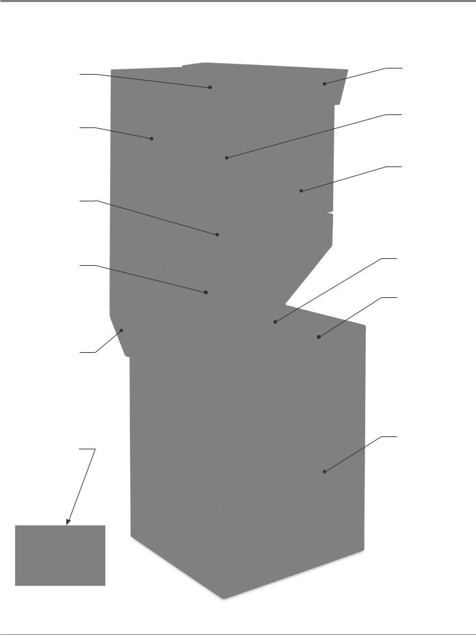
CONTROL PANEL
DRYER CABINET
DRYER FRONT
COVER
TRANSITION PANEL
SUPPORT BRACKET
ANTI-TIP BRACKETS
Figure 1 - 27” Stacked Laundry Center
CONTROL KNOBS
DOOR HANDLE
DRYER DOOR
WASHER LID
WASHER TOP
WASHER CABINET
27” Stacked Laundry Center n 1-3
GENERAL INFORMATION
Control Panel and Features
STANDARD VENT MODELS 1 |
2 |
|
|
|
3 |
6 |
|
||||||||||||||||||||||||||||||||||
|
|
|
|
|
|
|
|
|
|
|
|
|
|
|
|
|
|
|
|
|
|
|
|
|
|
|
|
|
|
|
|
|
|
|
|
|
|
|
|
|
|
|
|
|
|
|
|
|
|
|
|
|
|
|
|
|
|
|
|
|
|
|
|
|
|
|
|
|
|
|
|
|
|
|
|
|
|
|
|
|
|
|
|
|
|
|
|
|
|
|
|
|
|
|
|
|
|
|
|
|
|
|
|
|
|
|
|
|
|
|
|
|
|
|
|
|
|
|
|
|
|
|
|
|
|
|
|
|
|
|
|
|
|
|
|
|
|
|
|
|
|
|
|
|
|
|
|
|
|
|
|
|
|
|
|
|
|
|
|
|
|
|
|
|
|
|
|
|
|
|
|
|
|
|
|
|
|
|
|
|
|
|
|
|
|
|
|
|
|
|
|
|
|
|
|
|
|
|
|
|
|
|
|
|
|
|
|
|
|
|
|
|
|
|
|
|
|
|
|
|
|
|
|
|
|
|
|
|
|
|
|
|
|
|
|
|
|
|
|
|
|
|
|
|
|
|
|
|
|
|
|
|
|
|
|
|
|
|
|
|
|
|
|
|
|
|
|
|
|
|
|
|
|
|
|
|
|
|
|
|
|
|
|
|
|
|
|
|
|
|
|
|
|
|
|
|
|
|
|
|
|
|
|
|
|
|
|
|
|
|
|
|
|
|
|
|
|
|
|
|
|
|
|
|
|
|
|
|
|
|
|
|
|
|
|
|
|
|
|
|
|
|
|
|
|
|
|
|
|
|
|
|
|
|
|
|
|
|
|
|
|
|
|
|
|
|
|
|
|
|
|
|
|
|
|
|
|
|
|
|
|
|
|
|
|
|
|
|
|
|
|
|
|
|
|
|
|
|
|
|
|
|
|
|
|
|
|
|
|
|
|
|
|
|
|
|
|
|
|
|
|
|
|
|
|
|
|
|
|
|
|
|
|
|
|
|
|
|
|
|
|
|
|
|
|
|
|
|
|
|
|
|
|
|
|
|
|
|
|
|
|
|
|
|
|
|
|
|
|
|
|
|
|
|
|
|
|
|
|
|
|
|
|
|
|
|
|
|
|
|
|
|
|
|
|
|
|
|
|
|
|
|
|
|
|
|
|
|
|
|
|
|
|
|
|
|
|
|
|
|
|
|
|
|
|
|
|
|
|
|
|
|
|
|
|
|
|
|
|
|
|
|
|
|
|
|
|
|
|
|
|
|
|
|
|
|
|
|
|
|
|
|
|
|
|
|
|
|
|
|
|
|
|
|
|
|
|
|
|
|
|
|
|
|
|
|
|
|
|
|
|
|
|
|
|
|
|
|
|
|
|
|
|
|
|
|
|
|
|
|
|
|
|
|
|
|
|
|
|
|
|
|
|
|
|
|
|
|
|
|
|
|
|
|
|
|
|
|
|
|
|
|
|
|
|
|
|
|
|
|
|
|
|
|
|
|
|
|
|
|
|
|
|
|
|
|
|
|
|
|
|
|
|
|
|
|
|
|
|
|
|
|
|
|
|
|
|
|
|
|
|
|
|
|
|
|
|
|
|
|
|
|
|
|
|
|
|
|
|
|
|
|
|
|
|
|
|
|
|
|
|
|
|
|
|
|
|
|
|
|
|
|
|
|
|
|
|
|
|
|
|
|
|
|
|
|
|
|
|
|
|
|
|
|
|
|
|
|
|
|
|
|
|
|
|
|
|
|
|
|
|
|
|
|
|
|
|
|
|
|
|
|
|
|
|
|
|
|
|
|
|
|
|
|
|
|
|
|
|
|
|
|
|
|
|
|
|
|
|
|
|
|
|
|
|
|
|
|
|
|
|
|
|
|
|
|
|
|
|
|
|
|
|
|
|
|
|
|
|
|
|
|
|
|
4 |
|
|
|
|
|
|
|
7 |
|||||||
|
|
5 |
|
|
|
|
|
|
|
|||||||||||
LONG VENT MODELS |
1 |
|
2 |
|
|
|
3 |
6 |
|
|
||||||||||
|
|
|
|
|
|
|
|
|
|
|
|
|
|
|
|
|
|
|
|
|
|
|
|
|
|
|
|
|
|
|
|
|
|
|
|
|
|
|
|
|
|
|
|
|
|
|
|
|
|
|
|
|
|
|
|
|
|
|
|
|
|
|
|
|
|
|
|
|
|
|
|
|
|
|
|
|
|
|
|
|
|
|
|
|
|
|
|
|
|
|
|
|
|
|
|
|
|
|
|
|
|
|
|
|
|
|
|
|
|
|
|
|
|
|
|
|
|
|
|
|
|
|
|
|
|
|
|
|
|
|
|
|
|
|
|
|
|
|
|
|
|
|
|
|
|
|
|
|
|
|
|
|
|
|
|
|
|
|
|
|
|
|
|
|
|
|
|
|
|
|
|
|
|
|
|
|
|
|
|
|
|
|
|
|
|
|
|
|
|
|
|
|
|
|
|
|
|
|
|
|
|
|
|
|
|
|
|
|
|
|
|
|
|
|
|
|
|
|
|
|
|
|
|
|
|
|
|
|
|
|
|
|
|
|
|
|
|
|
|
|
|
|
|
|
|
|
|
|
|
|
|
|
|
|
|
|
|
|
|
|
|
|
|
|
|
|
|
|
|
|
|
|
|
|
|
|
|
|
|
|
|
|
|
|
|
|
|
|
|
|
|
|
|
|
|
|
|
|
|
|
|
|
|
|
|
|
|
|
|
|
|
|
|
|
|
|
|
|
|
|
|
|
|
|
|
|
|
|
|
|
|
|
|
|
|
|
|
|
|
|
|
|
|
|
|
|
|
|
|
|
|
|
|
|
|
|
|
|
|
|
|
|
|
|
|
|
|
|
|
|
|
|
|
|
|
|
|
|
|
|
|
|
|
|
|
|
|
|
|
|
|
|
|
|
|
|
|
|
|
|
|
|
|
|
|
|
|
|
|
|
|
|
|
|
|
|
|
|
|
5 |
4 |
7 |
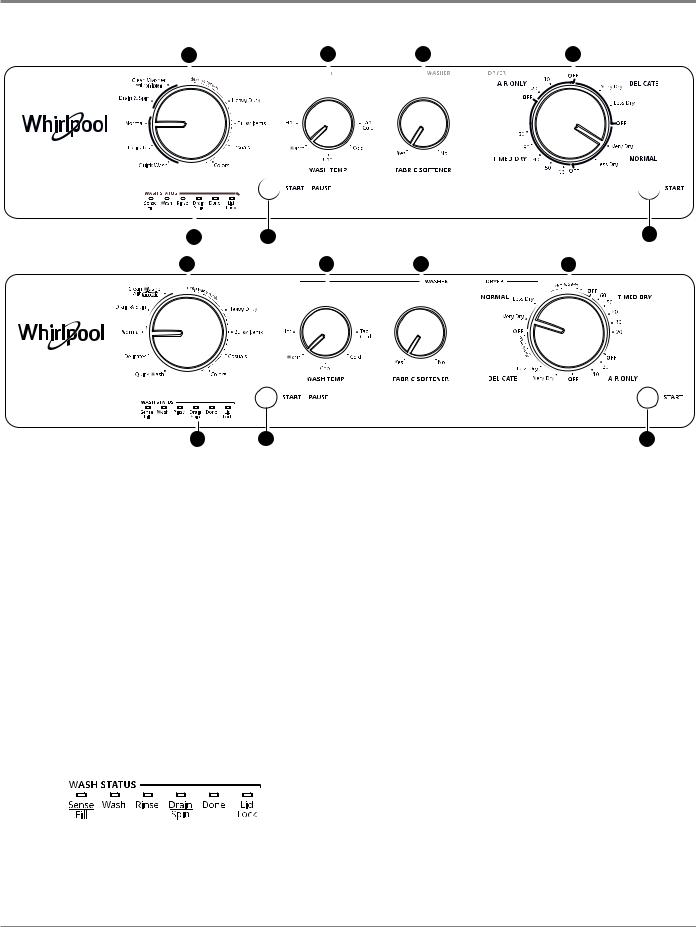
Not all features and options are available on all models. Appearance may vary.
Washer
1.WASH CYCLE KNOB
Use the Wash Cycle knob to select available cycles on your washer. Turn the knob to select a cycle for your laundry load.
See “Washer Cycle Guide” for detailed descriptions of cycles.
2.WASH TEMP
You may select a Wash Temperature based on the type of fabric and soils being washed. Use the warmest wash water safe for the fabric. Follow garment label instructions.
3.FABRIC SOFTENER
Set this knob to Yes when adding fabric softener to the fabric softener dispenser.
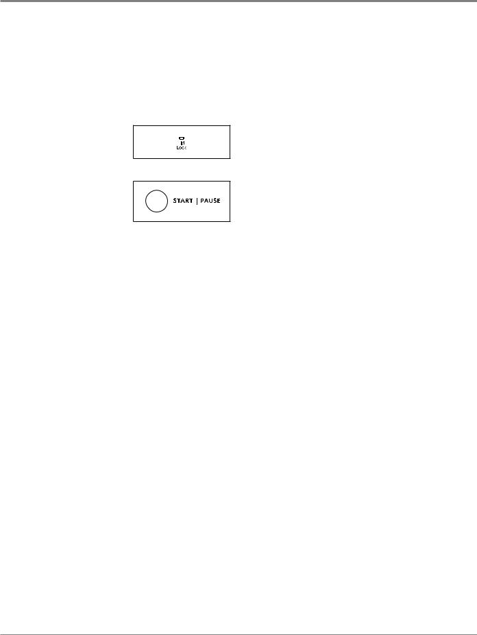
4.WASHER START/PAUSE
Press the START/PAUSE button to start the washer.
5.WASH STATUS INDICATOR LIGHTS
The Cycle Status lights show the progress of a cycle. At each stage of the process, you may notice sounds or pauses that are different from your previous washer.
SENSE/FILL
When the Start/Pause button is pressed, the washer will fill and begin sensing to determine load size and balance. Once sensing is complete, the washer will fill to the appropriate level for the detected load size and then begin the wash phase of the cycle.
NOTE: Sensing and wash phases will be paused by opening the unlocked lid. Close the lid to resume the cycle. If the lid is left open for more than 10 minutes, the washer will cancel the cycle and pump out the water. The lid will lock after the wash phase to begin the initial spinout and remain locked for the remainder of the cycle.
WASH
The washer will fill to the correct water level based on the load size. Certain cycles may agitate during the fill process to boost cleaning. You will hear the agitator rotate, followed by a pause lasting several seconds. When the wash cycle begins, you will hear the agitator increase speed. The motor sounds may change at different stages in the wash cycle while the washer performs different wash actions.
RINSE
Certain cycles use a spray rinse, which adds water to the tub while the basket spins. You may hear the motor turning on briefly (short hum) to move the basket while filling.
DRAIN/SPIN
The washer spins the load at increasing speeds for proper water removal, based on the selected cycle.
1-4 n 27” Stacked Laundry Center
GENERAL INFORMATION
Control Panel and Features (continued)
Washer (continued)
DONE
Once the cycle is complete, this light will come on. Remove the load promptly for best results.
LID LOCK
The Lid Lock feature allows for higher spin speeds. When the Lid Lock light is lit, the
lid is locked and cannot be
opened without pausing the cycle. When the light is off, the lid can be opened.
To open the lid after it has been locked, press START/ PAUSE. The lid will unlock once the washer movement has stopped. This may take several minutes if the load was spinning at high speed.
Press START/PAUSE again to resume the cycle.
Dryer
6.DRYER CYCLE KNOB
Use your Dryer Cycle knob to select available cycles on your dryer. Turn the knob to select a cycle for your laundry load. See “Dryer Cycle Guide” for detailed descriptions of cycles.
TIMED DRY
Will run the dryer for the specified time on the control. Drying time and temperature will depend on your dryer model.
NORMAL and DELICATE CYCLES
These cycles sense moisture in the load or air temperature and shut off when the load reaches the selected dryness level. They give the best drying in the shortest time.
Drying time will vary based on fabric type, load size, and dryness setting.
AIR ONLY
This cycle will run the dryer without heat for the specified time on the control.
7.DRYER START BUTTON
The Start button is used to start the dryer. Promptly removing clothes at the end of the cycle reduces wrinkling.
27” Stacked Laundry Center n 1-5
GENERAL INFORMATION
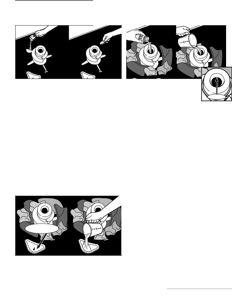
Using the Washer
Add Laundry Products |
Add Fabric Softener to Dispenser |
Figure X
Add a measured amount of HE detergent or single-dose laundry packet into the basket.
If using Oxi-type boosters, color-safe bleach, or fabric softener crystals, add to the bottom of the washer basket before adding clothes.
IMPORTANT: Use only High Efficiency detergents. The package will be marked “HE” or “High Efficiency.” Using non-HE detergent will likely result in longer cycle times and reduced rinsing performance. It may also result in component malfunction and, over time, buildup of mold or mildew. HE detergents should be low-sudsing and quick-dispersing to produce the right amount of suds for the best performance. They should hold soil in suspension so it is not redeposited onto clean clothes. Not all detergents labeled as High Efficiency are identical in formulation and their ability to reduce suds. For example, natural, organic, or homemade HE detergents may generate a high level of suds.
NOTE: Follow the manufacturer’s instructions to determine the amount of laundry products to use.
Add Liquid Chlorine Bleach to Dispenser
Do not overfill, dilute, or use more than 1 cup (236 mL). Do not use color-safe bleach or Oxi products in the same cycle with liquid chlorine bleach.
Liquid |
Chlorine Bleach |
Figure X
Figure X
MAX FILL
Pour a measured amount of liquid fabric softener into dispenser; always follow manufacturer’s directions for correct amount of fabric softener based on your load size.
Dilute liquid fabric softener by filling the dispenser with warm water until liquid reaches the underside of the rim. See max fill line arrows. Do not overfill.
Adding Liquid Fabric Softener Manually to Wash Load
During the final rinse, wait until the washer has completed filling and press the START/PAUSE button to pause the washer. Lift the lid and add the measured recommended amount of liquid fabric softener. Do not allow liquid fabric softener to spill, splash, drip, or run into the basket or on load. Do not use more than the recommended amount. Close the lid and press the START/ PAUSE button again to start the washer.
1-6 n 27” Stacked Laundry Center
GENERAL INFORMATION
Model/Serial Number Label & Tech Sheet Location
Model & Serial Number
Label Location
Tech Sheet Location
(Behind Transition Panel)
To access tech sheet, remove the top three screws indicated and lower transition panel.
Figure 9 - Tech Sheet Location
27” Stacked Laundry Center n 1-7

GENERAL INFORMATION
Model & Serial Number Nomenclature
MODEL NUMBER |
W |
E |
T |
40 |
27 |
H |
W |
0 |
INTERNATIONAL SALES OR
MARKETING CHANNEL
BRAND
W = Whirlpool
TYPE
E = Electric, G = Gas
ACCESS
T = Top Load
FEATURE SET
40 = Standard Vent, LV = Long Vent
SIZE
27 = 27” Width
YEAR OF INTRODUCTION
H = 2018
COLOR CODE
W = White
ENGINEERING CHANGE
0 = Basic Release; 1 = First Revision; etc.
SERIAL NUMBER |
|
M 7 25 10000 |
|
||
|
|
|
PRODUCTION SITE
M = Marion, OH
YEAR OF PRODUCTION
7 = 2017, 8 = 2018, etc.
WEEK OF PRODUCTION
PRODUCT SEQUENCE NUMBER
1-8 n 27” Stacked Laundry Center
|
|
|
|
|
|
|
GENERAL INFORMATION |
||
|
|
|
|
|
|
|
|
|
|
|
|
|
|
|
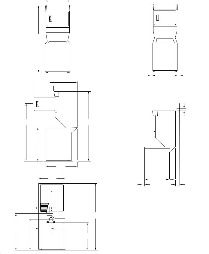
Dimensions & Clearances |
||||
Dimensions |
|
|
|
|
Clearances |
||||
Front View |
|
271/4" |
|
|
Side Clearances (recommended/minimum) |
||||
|
|
|
|
|
|
|
|
|
|
|
|
|
|
|
|
|
|
|
|
|
|
|
(692 mm) |
|
|
|
|||
75½" (1918 mm)
|
|
|
|
|
|
|
|
|
|
|
|
|
|
|
|
|
|
|
|
|
|
|
|
|
|
|
|
|
|
|
|
|
|
|
|
|
|
|
|
|
|
|
|
|
|
|
|
|
|
|
|
|
|
|
|
|
|
|
|
|
|
|
|
|
|
|
|
|
|
|
|
|
|
|
|
|
|
|
|
|
|
|
|
|
|
|
|
|
|
|
|
|
|
|
|
|
|
|
|
|
|
|
|
|
|
|
|
|
|
|
|
|
|
|
|
|
|
|
|
|
|
|
|
|
|
|
|
|
|
|
|
|
|
|
|
|
|
|
|
|
|
|
|
|
|
|
|
|
|
|
|
|
|
|
|
|
|
|
|
Side View |
1"/0" |
|
|
|
|
|
|
|
|
|
|
|
|
|
1"/0" |
||||||||||||||||
|
|
|
|
|
|
|
(25 mm/0 mm) |
|
|
|
|
|
|
|
|
|
|
|
|
(25 mm/0 mm) |
|||||||||||
|
|
|
|
|
|
|
|
|
|
|
|
|
|
|
|
|
|
|
|
||||||||||||
 4715/16"
(1218 mm)  2711/16"
 (704 mm)
Front/Back/Top Clearances (recommended/minimum)
1"/0"
(25 mm/0 mm)
6113/16" |
|
|
|
75½" |
||
(1570 mm) |
|
|
(1918 mm) |
|||
|
|
|
|
|
|
|
|
|
|
|
|
|
|
|
|
|
|
|
|
|
|
|
|
|
|
|
|
35¾" (908 mm)
|
|
327/16" |
|
|
(824 mm) |
Back View |
|
271/4" |
|
|
|
|
|
(692 mm) |
|
11½" |
|
|
(292 mm) |
75½" |
|
|
|
|
|
(1918 mm) |
|
|
13" |
45" |
39" |
(330 mm) |
(1143 mm) |
3615/16" |
|
|
(991 mm) |
|
|
|
(938 mm) |
1" |
5" |
(25 mm) |
(127 mm)** |
(Closet)* |
|
*Required spacing.
** Rear clearance may be 0” (0 mm) when house exhaust system is lined up directly with dryer exhaust.
27” Stacked Laundry Center n 1-9

GENERAL INFORMATION
|
Product Specifications |
|
|
ELECTRICAL |
|
|
|
Line Voltage : |
Electric = 240 VAC |
|
Gas = 120 VAC |
|
|
Frequency : |
57–63 Hz |
|
|
Amps : |
Electric - 30A |
|
Gas = 15 - 20A |
|
|
Operating Temperature Range : |
40–115°F (4.5–46°C) |
|
|
|
|
UTILITIES |
|
|
|
Water Temp : |
120°F (49°C) |
|
|
Water Pressure : |
15–125 PSI (103-862 kPa) |
|
|
Drain Height : |
39 in. to 8 ft. (991 mm to 2.4 m) |
|
|
|
|
WASHER DETAILS |
|
|
|
Capacity : |
Washer = 3.5 Cu Ft |
|
|
Motor Drive Type : |
Washer = Belt |
|
|
Drum Material : |
Powder Coat |
|
|
Control : |
Washer = Electronic |
|
|
Advanced Vibration Control : |
Yes |
|
|
Automatic Load Size Sensing : |
Yes |
|
|
Cycles : |
(9) Bulky Items, Casual, Clean Washer, Colors, Delicates, Drain & Spin, |
|
Heavy Duty, Normal, Quick Wash |
Wash/Rinse Temperatures : |
(5) Cold, Cool, Hot, Tap Cold, Warm |
|
|
Extra Rinse : |
Yes |
|
|
Spin : |
Maximum Spin Speed (RPM) 690 |
|
|
Suspension System : |
Suspended Tub - 4 Springs |
|
|
|
|
DRYER DETAILS |
|
|
|
Capacity : |
Dryer = 5.9 Cu Ft |
|
|
Motor Drive Type : |
Dryer = Belt |
|
|
Drum Material : |
Powder Coat |
|
|
Control : |
Dryer = Timer |
|
|
Moisture Sensor : |
Yes (Long Vent Only) |
|
|
Dryer Cycles : |
4 |
|
|
Venting : |
Rear Venting Only |
|
|
|
|
DIMENSIONS |
|
|
|
Depth : |
32 7/16” (824mm) |
|
|
Height : |
75 1/2” (1918mm) |
|
|
Width : |
27 1/4” (692mm) |
|
|
Net Weight : |
250 lbs. (113.4kg) |
|
|
|
|
1-10 n 27” Stacked Laundry Center

DIAGNOSTICS & TROUBLESHOOTING
Section 2:
Diagnostics &
Troubleshooting
This section provides diagnostic, fault codes, and troubleshooting information for the 27” Stacked Laundry Center.
WASHER & DRYER
Diagnostic Guide
WASHER ASSEMBLY
Diagnostic LED - Main Control (Washer)
Self Diagnostic Test Modes (Washer)
Activating the Service Diagnostic Test Mode (Washer)
Unsuccessful Entry
Exiting the Service Diagnostic Test Modes
Fault Code Display Mode
Automatic Test Mode
Manual Test Mode
Calibration Mode
UI Test Mode
Software Version Display Mode
Tachometer Verification Mode
Customer Viewable Fault Codes (Washer)
Fault/Error Codes (Washer)
Troubleshooting Guide (Washer)
DRYER ASSEMBLY
Troubleshooting Guide (Dryer)
Notes
27” Stacked Laundry Center n 2-1
DIAGNOSTICS & TROUBLESHOOTING
For Service Technician Use Only
Diagnostic Guide
Before servicing, check the following:
Make sure there is power at the wall outlet.
Has a household fuse blown or circuit breaker tripped? Was a regular fuse used? Inform customer that a timedelay fuse is required.
Is dryer vent properly installed and clear of lint or obstructions?
Are both hot and cold water faucets open and water supply hoses unobstructed?
Make sure drain hose is not sealed into drain pipe, and that there is an air gap for ventilation. Ensure drain height is between 39” (991 mm) and 8’ (2.4 m) above the floor.
All tests/checks should be made with a VOM (volt- ohm-milliammeter) or DVM (digital-voltmeter) having a sensitivity of 20,000 Ω per volt DC or greater.
Resistance checks must be made with washer unplugged or power disconnected.
IMPORTANT: Avoid using large diameter probes when checking harness connectors as the probes may damage the connectors upon insertion.
Check all harnesses and connections before replacing components. Look for connectors not fully seated, broken or loose wires and terminals, or wires not pressed into connectors far enough to engage metal barbs.
A potential cause of a control not functioning is corrosion or contamination on connections. Use an ohmmeter to check for continuity across suspected connections.
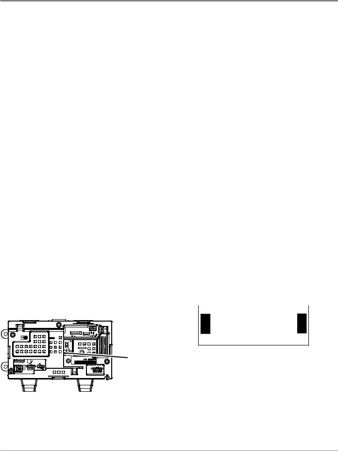
Diagnostic LED–Main Control (Washer)
A troubleshooting tool has been implemented onto the main control board—a diagnostic LED.
LED ON – The Control is detecting correct incoming line voltage and the processor is functioning.
LED OFF – Control malfunction. Perform TEST #1: Main Control, page 3-5, to verify main control functionality.
LED Location
Figure 1
ACTIVATING THE SERVICE
DIAGNOSTIC TEST MODES(WASHER)
1.Be sure the washer/dryer is in standby mode (plugged in with all indicators off). NOTE: After initial power is applied, wait 10 seconds before activating Service Diagnostic Test Modes.
2.Perform the following sequence of movement using the cycle selector knob. NOTE: AFTER RESET, sequence “a” through “e” must be completed within 6 seconds.
RESET - Rotate cycle selector knob
4/ counterclockwise one or more clicks to clear sequence.
3a. Rotate cycle selector knob clockwise one click 5 and wait ½ second.
3b. Rotate cycle selector knob clockwise one click 5 and wait ½ second.
3c. Rotate cycle selector knob clockwise one click
5 and wait ½ second.
4/ d. Rotate cycle selector knob counterclockwise one click and wait ½ second.
35 e. Rotate cycle selector knob clockwise one click.
¾ Successful activation of Diagnostic Test Modes will
be indicated by all status LEDs (except for Lid Lock)
flashing ON and OFF in half-second intervals. NOTE:
LED names may vary between makes and models.
Legend: |
|
|
= ON |
|
= OFF |
|||||||
|
|
|
||||||||||
|
|
|
|
|
|
|
|
|
|
|
|
|
|
|
|
|
0.5 Seconds ON |
|
|
|
|||||
|
|
|
|
|
|
|
|
|
|
|
|
|
|
|
|
|
|
|
|
|
|
|
|
|
|
Sense |
Wash Rinse Drain |
|
Done |
|||||||||
|
Fill |
|
|
|
|
|
Spin |
|
|
|
||
|
|
|
|
|
|
|
|
|
|
|
|
|
|
|
|
|
|
|
|
|
|
|
|
|
|
0.5 Seconds OFF
Figure 2 - Status LEDs flashing ON and OFF
¾ If the status LEDs do not display as described above, the sequence may not have been completed within 6 seconds. Repeat step 2 to ensure this was not the cause. If still unsuccessful, see Unsuccessful Entry, page 2-3.
Self Diagnostic Test Modes (Washer)
These tests allow factory or service personnel to test and verify all inputs to the main control board. You may want to do a quick and overall checkup of the washer with these tests before going to specific troubleshooting tests.
2-2 n 27” Stacked Laundry Center

DIAGNOSTICS & TROUBLESHOOTING
For Service Technician Use Only
3.There are several accessible Diagnostic Test Modes shown in the chart below. To select the desired Mode of Operation, turn the cycle selector knob until the status LEDs match the mode desired to enter.
DIAGNOSTIC TEST MODES
|
MODE |
|
STATUS LEDs |
|
DISPLAY |
|||||
|
(Status LED names may vary |
WASH |
|
RINSE |
DRAIN |
|
SPIN |
|
DONE |
(Only on models |
|
|
|
|
|||||||
|
|
|
|
|
|
|
|
|
||
|
between makes and models) |
|
|
|
|
|
|
|
|
with a display) |
|
|
|
|
|
|
|
|
|
|
|
|
|
|
|
|
|
|
|
|
|
|
|
Fault Code Display Mode |
|
|
|
|
|
|
|
|
0 1 |
|
Automatic Test Mode |
|
|
|
|
|
|
|
|
02 |
|
Manual Test Mode |
|
|
|
|
|
|
|
|
03 |
|
Calibration Mode |
|
|
|
|
|
|
|
|
04 |
|
Sales Demo Mode |
|
|
|
|
|
|
|
|
05 |
|
UI Test Mode |
|
|
|
|
|
|
|
|
06 |
|
SW Version Display Mode |
|
|
|
|
|
|
|
|
07 |
|
Factory Diagnostics Mode |
|
|
|
|
|
|
|
|
08 |
|
Tachometer Verification |
|
|
|
|
|
|
|
|
09 |
|
Dry Factory Diagnostics |
|
|
|
|
|
|
|
|
10 |
|
Factory Cal Test Cycle |
|
|
|
|
|
|
|
|
1 1 |
|
AATCC Cycle |
|
|
|
|
|
|
|
|
14 |
|
NVH Cycle |
|
|
|
|
|
|
|
|
15 |
4.Press the START button to enter desired mode of operation.
Refer to the following pages for detailed information on each mode of operation:
FAULT CODE DISPLAY MODE: Page 2-3AUTOMATIC TEST MODE: Page 2-4MANUAL TEST MODE: Page 2-4
CALIBRATION MODE: Page 2-4
SALES DEMO: NOT FOR SERVICE USE*
UI TEST MODE: Page 2-4
SW VERSION DISPLAY MODE: Page 2-5
FACTORY DIAGNOSTICS: NOT FOR SERVICE USE.*
If accessed, washer must be recalibrated (see Calibration Mode)
TACHOMETER VERIFICATION MODE: Page 2-5
DRY FACTORY DIAGNOSTICS: NOT FOR SERVICE USE*FACTORY CAL TEST CYCLE: NOT FOR SERVICE USE*
AATCC CYCLE: NOT FOR SERVICE USE*
NVH CYCLE: NOT FOR SERVICE USE* *Press and hold START for 3 seconds to exit.
Unsuccessful Entry
If entry into diagnostic test mode is unsuccessful, refer to the following indication and action:
Indication: None of the LEDs turn on.
Action: Press START button to enter setting mode.
¾ If indicators come on, repeat steps 1 through 4 of Activating the Service Diagnostic Modes. NOTE: Rotating the dial too fast or too slow will affect entry.
¾ If no indicators come on after pressing the START button, go to TEST #1, page 3-5.
EXITING THE SERVICE DIAGNOSTIC
TEST MODES (WASHER)
Press and hold the START button for 3 seconds at any time to exit diagnostic test modes.
Washer will exit diagnostic test modes after 5 minutes of inactivity or unplugging the power cord.
Fault Code Display Mode (Pgs2-6to2-9)
To access fault/error codes, perform steps 1 and 2 of Activating the Service Diagnostic Test Modes. Turn the cycle selector knob until the status LEDs correspond as follows:
“Done” LED On
|
|
|
|
|
|
|
|
|
|
|
|
|
|
Sense |
Wash |
Rinse |
Drain |
Done |
|||||||||
|
Fill |
|
|
|
|
|
|
|
Spin |
|
|
||
Press the START button to enter Fault Code
Display Mode. The status LEDs flash on and off. 1. To view last four fault codes:
¾ Turn cycle selector knob clockwise to view fault codes in the order of most recent to oldest. (Refer to Fault/ Error Code charts on pages 2-6 to 2-7.)
NOTE: A fault/error code will be removed from memory if it does not reoccur after 10 consecutive wash cycles.
2. To clear fault codes:
¾ Turn cycle selector knob until the status LEDs flash ON and OFF (see figure 2, page 2-2).
¾ Press and hold the START button for 3 seconds to clear all fault codes and exit Fault Code Display Mode.
Fault/Error Code Display Method
Fault/error codes are displayed by alternating the state of the Status LEDs in one second intervals. All fault/error codes have an F# and an E#. The F# indicates the suspect System/Category and the E# indicates the suspect Component system.
If the Sense/Fill LED is ON, the Fault Number is represented; if OFF, the Error Number is represented (see example below). The remaining LEDs (Wash, Rinse, Drain/Spin, and Done) represent the fault and error code in binary. (See Fault/Error Code Charts on pages 2-6 to 2-7 for more information.)
information.) |
|
|
|
|
|
|
|
= ON. |
||||
|
|
|
|
|
|
|
||||||
|
|
|
|
|
|
|
|
|
|
|
|
|
|
|
|
|
|
STATUS LEDs |
|
Fault / Error Code |
|
Frame Timing (sec.) |
|||
Frame Number |
|
|
|
|
|
|
|
|
|
|||
SENSE |
FILL |
|
WASH |
|
RINSE |
DRAIN |
SPIN |
DONE |
|
|||
|
|
|
|
|
|
|
|
|
|
|
|
|
1 |
F |
|
8 |
|
4 |
2 |
1 |
F2 |
|
0.5 |
||
2 |
|
|
|
|
|
|
|
|
|
|
|
0.5 |
3 |
E |
|
8 |
|
4 |
2 |
1 |
E3 |
|
0.5 |
||
4 |
|
|
|
|
|
|
|
|
|
|
|
1.0 |
|
|
|
|
|
|
Repeat… |
|
|
|
|
||
LED names may vary between makes and models.
27” Stacked Laundry Center n 2-3

DIAGNOSTICS & TROUBLESHOOTING
For Service Technician Use Only
Automatic Test Mode (Page 2-10)
To access Automatic Test Mode, perform steps 1 and 2 of Activating the Service Diagnostic Test Modes. Turn the cycle selector knob until the status LEDs correspond as follows:
“Drain/Spin” LED On
|
|
|
|
|
|
|
|
|
|
|
|
|
|
Sense |
Wash |
Rinse |
Drain |
Done |
|||||||||
|
Fill |
|
|
|
|
|
|
Spin |
|
|
|||
NOTE: Status LED names may vary between makes and models.
Press the START button to begin the automatic test. See page 2-10 for order of automatic test.
Upon entering the automatic test mode, the washer will perform an automatic test with water cycles to check major washer functions.
Pressing the START button will manually advance to the next step.
Press and hold the START button for 3 seconds at any time to exit Automatic Test mode.
IMPORTANT: Lid must be closed with lid lock enabled to perform test.
Manual Test Mode (Page 2-11)
To access Manual Test Mode, perform steps 1 and 2 of Activating the Service Diagnostic Test Modes. Turn the cycle selector knob until the status LEDs correspond as follows:
“Drain/Spin” & “Done” LEDs On
|
|
|
|
|
|
|
|
|
|
|
|
|
|
Sense |
Wash |
Rinse |
Drain |
Done |
|||||||||
|
Fill |
|
|
|
|
|
|
Spin |
|
|
|||
Press the START button to enter Manual Test Mode. See page 2-11 for manual test mode.
Upon entering the manual test mode, the washer will have all outputs OFF.
The cycle selector knob is used to select the output to be tested.
The Start button will activate/deactivate the selected output.
When the selected output is activated, the corresponding status LEDs flash ON & OFF.
Press and hold the START button for 3 seconds at any time to exit Manual test mode.
IMPORTANT: As a safety feature, the lid must be closed with lid lock enabled to activate either Agitate or Spin Test.
NOTE: Multiple outputs may be activated simultaneously. NOTE: Outputs left on will time-out after 5 minutes.
Calibration Mode
NOTE: Calibration only applies to models that do not have level selection.
IMPORTANT: Calibration must be performed when any of the following components have been replaced: Main Control, Basket, Drive Assembly, Suspension, Motor, and Capacitor. Not performing calibration will result in poor wash performance.
Do NOT interrupt calibration, disturb washer, or remove power; otherwise, calibration must be repeated.
Lid must be down to perform test.
Basket must be empty to perform test (no water or clothes).
Calibration cycle runs for approximately 2–4 minutes.* Cycle completes when lid unlocks and washer enters standby mode.
*If Calibration Mode is run on a washer with a porcelain basket, the time necessary to complete the calibration may be longer.
NOTE: Before beginning calibration, check the drive system to verify that the cam on the splutch is moving freely and not binding.
To access Calibration Mode, perform steps 1 and 2 of Activating the Service Diagnostic Test Modes. Turn the cycle selector knob until the status LEDs correspond as follows:
“Rinse” LED On
|
|
|
|
|
|
|
|
|
|
|
|
|
|
Sense |
Wash |
Rinse |
Drain |
Done |
|||||||||
|
Fill |
|
|
|
|
|
|
|
Spin |
|
|
||
NOTE: Status LED names may vary between makes and models.
Press the START button to begin washer calibration. All status LEDs will turn on.
UI Test Mode
To access UI (User Interface) Test Mode, perform steps 1 and 2 of Activating the Service Diagnostic Test Modes. Turn the cycle selector knob until the status LEDs correspond as follows:
“Rinse” & “Drain/Spin” LEDs On
|
|
|
|
|
|
|
|
|
|
|
|
(1)Sense (2)Wash (3)Rinse |
(4)Drain (5)Done |
||||||||||
(1) Fill |
(4)Spin |
||||||||||
NOTE: Status LED names may vary between makes and models. Use LED # identifications.
Press the START button to begin the UI test.
Upon entering the UI test mode, all status LEDs will be turned ON.
Pressing the Start button will turn on and off all status LEDs, or toggle the state of each status LED independently. (Example: if 2 are on, and 3 are off, then 2 will be turned off and 3 turned on.)
2-4 n 27” Stacked Laundry Center

DIAGNOSTICS & TROUBLESHOOTING
For Service Technician Use Only
When rotating the cycle selector knob, each click “indent”
toggles the “Done” (5) LED.
Turning the rotary switches will toggle the following status
LEDs on and off.
•Rotary Switch #1 – toggles (1) Sense/Fill LED
•Rotary Switch #2 – toggles (2) Wash LED
•Rotary Switch #3 – toggles (3) Rinse LED
•Rotary Switch #4 – toggles (4) Drain/Spin LED
NOTE: The number and location of rotary switches varies between makes and models. Switches are read from left to right, the leftmost switch being #1.
Press and hold the START button for 3 seconds at any time to exit UI test mode.
Washer will exit UI test mode after 5 minutes of inactivity or unplugging the power cord.
Software Version Display Mode
To access Software Version Display Mode, perform steps 1 and 2 of Activating the Service Diagnostic Test Modes. Turn the cycle selector knob until the status LEDs correspond as follows:
“Rinse,” “Drain/Spin,” and “Done” LEDs On
|
|
|
|
|
|
|
|
|
|
|
|
|
|
Sense |
Wash |
Rinse |
Drain |
Done |
|||||||||
|
Fill |
|
|
|
|
|
|
|
Spin |
|
|
||
NOTE: Status LED names may vary between makes and models.
Press the START button to begin software display mode.
Upon entering the software version display mode, the Major, Minor, and Test version numbers for the software are displayed by alternating the state of the Status LEDs in one second intervals; the process repeats following a pause.
For example, if the s/w version is 02.01.17, the following sequence would be displayed:
16 |
8 |
4 |
2 |
1 |
02
01
17
Sense Wash Rinse |
Drain |
Done |
Fill |
Spin |
|
Press and hold the START button for 3 seconds at any time
to exit software version display mode.
Tachometer Verification Mode
To access Tachometer Verification Mode, perform steps 1 and 2 of Activating the Service Diagnostic Modes. Turn the cycle selector knob until the status LEDs correspond as follows:
“Wash” and “Done” LEDs On
|
|
|
|
|
|
|
|
|
|
|
|
|
|
Sense |
Wash |
Rinse |
Drain |
Done |
|||||||||
|
Fill |
|
|
|
|
|
|
|
Spin |
|
|
||
NOTE: Status LED names may vary between makes and models.
Press the START button to begin tachometer verification mode.
Tachometer verification uses the status LEDs to represent the tachometer frequency (basket RPM).
For example, slowly turn the basket by hand; as the basket turns, the DONE, DRAIN/SPIN, RINSE, and WASH status LEDs will illuminate one at a time in a visually repeating cycle. The LED timing is derived from the tachometer signal itself.
Press and hold the START button for 3 seconds at any time to exit tachometer verification mode.
Customer Viewable Fault Codes (Washer)
There are three fault codes that may be visible to the customer indicated by the following Status LEDs:
WASH LED ON (Long Fill Fault) – Refer to “No Fill, Long Fill” on page 2-8 for information.
DRAIN/SPIN LED ON (Long Drain Fault) – Refer to “Long Drain” on page 2-9 for information.
LID LOCK LED FLASHING CONTINUOUSLY (Lid Lock Fault) – Run TEST #3: Drive System on page 3-8. According to the result, refer to “Basket Speed Fault,” “Shifter Fault,” “Motor Fault,” or “Motor Unable to Reach Target RPM” on page 2-8. Finally, refer to “Lid Lock Fault” on page 2-7.
FOR SERVICE FAULT AND ERROR CODES, CONTINUE TO PAGES 2-6 TO 2-9
27” Stacked Laundry Center n 2-5
DIAGNOSTICS & TROUBLESHOOTING
For Service Technician Use Only
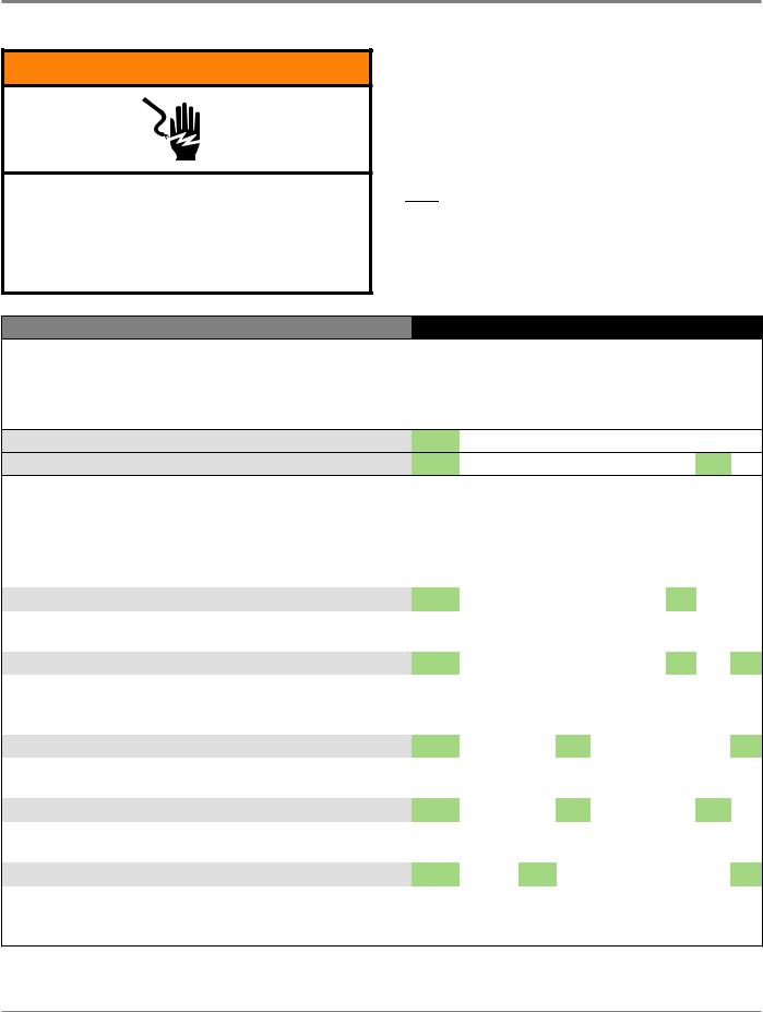
 WARNING
Electrical Shock Hazard Disconnect power before servicing.
Replace all parts and panels before operating.
Failure to do so can result in death or electrical shock.
Fault/Error Codes (Washer)
See page 2-3 to access Fault Code Display Mode.
* If the Sense/Fill LED is ON, the fault code is represented; if OFF, the error code is represented.

 = ON
= ON
FAULT/ERROR CODE - DESCRIPTION
Explanation & Recommended Procedure
(Status LED names may vary between makes and models)
F0E0 - NO FAULT
F0E2 - OVERSUDS CONDITION DETECTED
|
FAULT NUMBER |
|
ERROR NUMBER |
|
||||||
|
|
Status LEDs |
|
|
Status LEDs |
|
||||
|
|
|
|
|
||||||
|
|
|
|
|
|
|
|
|
|
|
SENSE FILL |
|
WASH |
RINSE |
DRAIN SPIN |
DONE |
SENSE FILL |
WASH |
RINSE |
DRAIN SPIN |
DONE |
On |
|
8 |
4 |
2 |
1 |
Off |
8 |
4 |
2 |
1 |
F |
|
|
|
|
|
E |
|
|
2 |
|
|
|
|
|
|
|
|
|
|
|
|
Fault is displayed when suds prevent the basket from spinning up to speed or the pressure sensor detects rising suds level. The main control will flush water in attempt to clear suds. If the water flush is unable to correct the problem, this may indicate:
•Not using HE detergent.
•Excessive detergent usage.
•Check pressure hose connection from tub to pressure sensor. Is hose pinched, kinked, plugged, or leaking air?
•Mechanical friction on drive mechanism or basket (clothing between basket and tub).
F0E4 – HIGH WATER TEMPERATURE – RINSE CYCLE |
|
F |
|
|
|
|
|
E |
|
4 |
|
|
|
|
|
|
|
|
|
|
|
|
|
|
|
Fault is displayed when washer detects water temperature 105°F (40°C) or higher during rinse cycle. |
|
|
|
|
|
|||||||
• Hot water getting in. Make sure inlet hoses are connected correctly. |
|
|
|
|
|
|
|
|
|
|
|
|
|
|
|
|
|
|
|
||||||
F0E5 – OFF BALANCE LOAD DETECTED |
|
F |
|
|
|
|
|
E |
|
4 |
|
1 |
|
|
|
|
|
|
|
|
|
|
|
|
|
Fault is displayed when an off balance condition is detected.
•Check for weak suspension. Basket should not bounce up and down more than once when pushed.
•Clothing should be distributed evenly when loading.
F1E1 – MAIN CONTROL FAULT |
F |
|
|
|
1 |
E |
|
|
|
1 |
|
|
|
|
|
|
|
|
|
|
|
Indicates a main control fault. |
|
|
|
|
|
|
|
|
|
|
• See TEST #1: Main Control, page 3-5. |
|
|
|
|
|
|
|
|
|
|
|
|
|
|
|
|
|||||
F1E2 – MOTOR CONTROL FAULT |
F |
|
|
|
1 |
E |
|
|
2 |
|
|
|
|
|
|
|
|
|
|
|
|
Indicates a fault of the motor control section of the main control. |
|
|
|
|
|
|
|
|
|
|
• See TEST #3b: Drive System – Motor, page 3-10. |
|
|
|
|
|
|
|
|
|
|
|
|
|
|
|
|
|||||
F2E1 – STUCK KEY |
F |
|
|
2 |
|
E |
|
|
|
1 |
|
|
|
|
|
|
|
|
|
|
|
One or more keys on the User Interface were actuated for 15 consecutive seconds.
•Fault occurs during Diagnostic Test Mode if a stuck key is detected.
•See TEST #4: Console and Indicators, page 3-12.
Continued on next page . . .
2-6 n 27” Stacked Laundry Center
DIAGNOSTICS & TROUBLESHOOTING
For Service Technician Use Only
Fault/Error Codes (Washer) Continued
FAULT/ERROR CODE - DESCRIPTION
Explanation & Recommended Procedure
(Status LED names may vary between makes and models)
F2E3 – SWITCH MISMATCH
|
FAULT NUMBER |
|
ERROR NUMBER |
|
||||||
|
|
Status LEDs |
|
|
Status LEDs |
|
||||
|
|
|
|
|
||||||
|
|
|
|
|
|
|
|
|
|
|
SENSE FILL |
|
WASH |
RINSE |
DRAIN SPIN |
DONE |
SENSE FILL |
WASH |
RINSE |
DRAIN SPIN |
DONE |
F |
|
8 |
4 |
2 |
1 |
E |
8 |
4 |
2 |
1 |
|
|
|
|
|
|
|
|
|
|
|
The switches do not match the console or are not operating correctly.
•Fault occurs during Diagnostic Test Mode if a switch mismatch is detected.
•See TEST #4: Console and Indicators, page 3-12.
F3E1 – PRESSURE SYSTEM FAULT |
F |
|
|
2 |
1 |
E |
|
|
|
1 |
|
|
|
|
|
|
|
|
|
|
|
Fault is displayed when the Main Control detects an out of range pressure signal. |
|
|
|
|
|
|
|
|
||
• Check pressure hose connection from tub to pressure sensor. Is hose pinched, kinked, plugged, or leaking air? |
|
|
|
|||||||
• See TEST #5: Water Level, page 3-13. |
|
|
|
|
|
|
|
|
|
|
|
|
|
|
|
|
|
||||
F5E1 – LID SWITCH FAULT |
F |
|
4 |
|
1 |
E |
|
|
|
1 |
|
|
|
|
|
|
|
|
|
|
|
Fault is displayed if lid is in locked state, but lid switch is open; control not sensing the strike in the lid lock.
•User presses Start with lid open.
•The main control cannot detect the lid switch opening and closing properly.
•Strike not assembled correctly on the lid.
•Lid lock bezel not installed correctly (must be square to embossing and flush to top).
•See TEST #7: Lid Lock, page 3-15.
F5E2 – LID LOCK FAULT |
F |
|
4 |
|
1 |
E |
|
|
2 |
|
|
|
|
|
|
|
|
|
|
|
|
Fault is displayed if lid lock has not moved into locked position or motor cannot be powered.
•Lid is not closed completely due to interference.
•Check for lock interference with lock striker.
•Wash media buildup (detergent, lint, etc.) is preventing the lock mechanism from sliding.
•Main control detects open lid switch when attempting to lock.
•Main control cannot determine if lid lock is in a locked state.
•See TEST #7: Lid Lock, page 3-15.
F5E3 – LID UNLOCK FAULT |
F |
|
4 |
|
1 |
E |
|
|
2 |
1 |
|
|
|
|
|
|
|
|
|
|
|
Fault is displayed if lid lock has not moved into unlocked position or motor cannot be powered.
•Check for lock interference with lock striker.
•Main control cannot determine if lid lock is in an unlocked state.
•See TEST #7: Lid Lock, page 3-15.
F5E4 – LID NOT OPENED BETWEEN CYCLES |
F |
|
4 |
|
1 |
E |
|
4 |
|
|
|
|
|
|
|
|
|
|
|
|
|
Fault is displayed if the following conditions occur:
•User presses Start after several consecutive washer cycles without opening lid.
•See TEST #7: Lid Lock, page 3-15.
Continued on next page . . .
27” Stacked Laundry Center n 2-7

DIAGNOSTICS & TROUBLESHOOTING
For Service Technician Use Only
Fault/Error Codes (Washer) Continued
FAULT/ERROR CODE - DESCRIPTION
Explanation & Recommended Procedure
(Status LED names may vary between makes and models)
F7E1 – BASKET SPEED FAULT
|
FAULT NUMBER |
|
ERROR NUMBER |
|
||||||
|
|
Status LEDs |
|
|
Status LEDs |
|
||||
|
|
|
|
|
||||||
|
|
|
|
|
|
|
|
|
|
|
SENSE FILL |
|
WASH |
RINSE |
DRAIN SPIN |
DONE |
SENSE FILL |
WASH |
RINSE |
DRAIN SPIN |
DONE |
F |
|
|
4 |
2 |
1 |
E |
|
|
|
1 |
|
|
|
|
|
|
|
|
|
|
|
Fault is displayed when the main control cannot determine speed of basket, or speed changes too quickly.
•See TEST #3: Drive System, page 3-8.
•Calibration - run Calibration Mode, page 2-4.
•Locked rotor - check that basket, impeller, and motor can rotate freely.
•Check harness connections from main control to motor and shifter.
•See TEST #3a: Drive System-Shifter, page 3-8.
•Control not sensing the basket move in spin—run Tachometer Verification Mode, page 5.
•Bad motor capacitor, motor or capacitor connector disconnected, or broken wires to motor or capacitor.
•Belt is off or pulley is loose—check drive belt. Verify that belt is fully installed on both pulleys. Also, check that the pulleys are fastened securely to the motor shaft and agitator shaft.
•See TEST #3b: Drive System–Motor, page 3-10.
•For more details, see document W10606242.
F7E5 – SHIFTER FAULT |
F |
|
4 |
2 |
1 |
E |
|
4 |
|
1 |
|
|
|
|
|
|
|
|
|
|
|
Fault is displayed when the main control cannot determine position of shifter.
•See TEST #3: Drive System, page 3-8.
•Check harness connections from main control to motor and shifter.
•Observe shifter operation.
•See TEST #3a: Drive System–Shifter, page 3-8.
F7E6 – MOTOR FAULT |
F |
|
4 |
2 |
1 |
E |
|
4 |
2 |
|
|
|
|
|
|
|
|
|
|
|
|
Indicates an open clockwise or counterclockwise circuit of the motor.
•See TEST #3: Drive System, page 3-8.
•See TEST #3b: Drive System–Motor, page 3-10.
F7E7 – MOTOR UNABLE TO REACH TARGET RPM |
F |
|
4 |
2 |
1 |
E |
|
4 |
2 |
1 |
|
|
|
|
|
|
|
|
|
|
|
Fault is displayed when basket speed sensor detects that target RPM was not reached.
•See TEST #3: Drive System, page 3-8.
•Mechanical friction on drive mechanism or basket (clothing between basket and tub).
•Weak motor or run capacitor, or no connection to run capacitor.
•Load off balance. Clothing should be distributed evenly when loading.
•See TEST #3b: Drive System–Motor, page 3-10.
F8E1 – NO FILL, LONG FILL |
F |
8 |
|
|
|
E |
|
|
|
1 |
|
|
|
|
|
|
|
|
|
|
|
Fault is displayed when the water level does not change for a period of time OR water is present but main control does not detect the water level changing.
•Is water supply connected and turned on?
•Low water pressure; fill times longer than six minutes. Are hose screens plugged?
•Check for proper drain hose installation. Is water siphoning out of the drain hose?
•Drain hose must not be more than 4.5” (114 mm) into the drain pipe.
•Check pressure hose connection from tub to pressure sensor. Is hose pinched, kinked, plugged, or leaking air?
•See TEST #2: Valves, page 3-7.
Continued on next page . . .
2-8 n 27” Stacked Laundry Center

DIAGNOSTICS & TROUBLESHOOTING
For Service Technician Use Only
Fault/Error Codes (Washer) Continued
FAULT/ERROR CODE - DESCRIPTION
Explanation & Recommended Procedure
(Status LED names may vary between makes and models)
F8E3 – OVERFLOW CONDITION
|
FAULT NUMBER |
|
ERROR NUMBER |
|
||||||
|
|
Status LEDs |
|
|
Status LEDs |
|
||||
|
|
|
|
|
||||||
|
|
|
|
|
|
|
|
|
|
|
SENSE FILL |
|
WASH |
RINSE |
DRAIN SPIN |
DONE |
SENSE FILL |
WASH |
RINSE |
DRAIN SPIN |
DONE |
F |
|
8 |
|
|
|
E |
|
|
2 |
1 |
|
|
|
|
|
|
|
|
|
|
|
Fault is displayed when main control senses water level that exceeds the washer’s capacity.
•May signify problem with inlet water valves.
•Check pressure hose connection from tub to pressure sensor. Is hose pinched, kinked, plugged, or leaking air?
•Onboard pressure transducer fault.
•Check for proper drain hose installation. Is water siphoning out of the drain hose? Drain hose must not be more than 4.5” (114 mm) into the drain pipe. Make sure drain hose is not seated into drain pipe, and that there is an air gap for ventilation. Ensure drain height is between 39” (991 mm) and 8’ (2.4 m) above the floor.
•See TEST #2: Valves, page 3-7 and TEST #5: Water Level, page 3-13.
F8E5 – HOT, COLD REVERSED |
F |
8 |
|
|
|
E |
|
4 |
|
1 |
|
|
|
|
|
|
|
|
|
|
|
Fault is displayed when the hot and cold inlet hoses are reversed. |
|
|
|
|
|
|
|
|
|
|
• Make sure inlet hoses are connected correctly. |
|
|
|
|
|
|
|
|
|
|
• See TEST #2: Valves, page 3-7. |
|
|
|
|
|
|
|
|
|
|
|
|
|
|
|
|
|
|
|||
F9E1 – LONG DRAIN |
F |
8 |
|
|
1 |
E |
|
|
|
1 |
|
|
|
|
|
|
|
|
|
|
|
Fault is displayed when the water level does not change after the drain pump is on for 10 minutes.
•Is the drain hose or the drain pump clogged? Check tub sump under impeller for obstructions.
•Is the drain hose height greater than 8’ (2.4 m)?
•Too much detergent.
•Check pressure hose connection from tub to pressure sensor. Is hose pinched, kinked, plugged, or leaking air?
•Is the pump running? If not, see TEST #6: Drain Pump, page 3-14.
27” Stacked Laundry Center n 2-9

DIAGNOSTICS & TROUBLESHOOTING
For Service Technician Use Only
Automatic Test Mode (Washer) - See page 2-4 to access Automatic Test Mode.
Press the START button to begin the Automatic Test.
IMPORTANT: Lid must be closed and locked to perform Automatic Test.
FUNCTION |
STATUS LEDs |
|
|||
|
|
|
|
|
|
Recommended Procedure |
WASH |
RINSE |
DRAIN SPIN |
DONE |
|
(Status LED names may vary between makes and models) |
|||||
|
|
|
|
||
LID WILL LOCK |
|
|
|
1 |
|
Motor must be at “0” RPM. If lid does not lock, go to Manual Test: Lid Lock, page 2-11. |
|
|
|
||
|
|
|
|
|
|
COLD VALVE WILL ACTUATE |
|
|
2 |
|
|
If water is not present, go to Manual Test: Cold Valve, page 2-11. |
|
|
|
|
|
|
|
|
|
|
|
HOT VALVE WILL ACTUATE |
|
|
2 |
1 |
|
If water is not present, go to Manual Test: Hot Valve, page 2-11. |
|
|
|
|
|
|
|
|
|
|
|
RESERVED FOR FUTURE DEVELOPMENT |
|
4 |
|
|
|
Washer will pause for 5 seconds. |
|
|
|
|
|
|
|
|
|
|
|
RESERVED FOR FUTURE DEVELOPMENT |
|
4 |
|
1 |
|
Hot water valve will actuate for the specified time period. |
|
|
|
|
|
|
|
|
|
|
|
RESERVED FOR FUTURE DEVELOPMENT |
|
4 |
2 |
|
|
Cold water valve will actuate for the specified time period. |
|
|
|
|
|
|
|
|
|
|
|
HOT & COLD VALVE WILL ACTUATE |
|
4 |
2 |
1 |
|
Hot & cold water valves will actuate for the specified time period. |
|
|
|
|
|
|
|
|
|
|
|
SHIFTER MOVES TO AGITATION POSITION |
8 |
|
|
|
|
If motor does not agitate, go to Manual Test: Gentle or Heavy Agitation, page 2-11. |
|
|
|
|
|
|
|
|
|
|
|
MOTOR AGITATES |
8 |
|
|
1 |
|
If motor does not agitate, go to Manual Test: Gentle or Heavy Agitation, page 2-11. |
|
|
|
|
|
|
|
|
|
|
|
DRAIN PUMP WILL ACTUATE |
8 |
|
2 |
|
|
If water is not draining, go to Manual Test: Drain, page 2-11. |
|
|
|
|
|
|
|
|
|
|
|
SHIFTER MOVES TO SPIN POSITION |
8 |
|
2 |
1 |
|
If basket is not turning, go to Manual Test: Low or High Spin, page 2-11. |
|
|
|
|
|
|
|
|
|
|
|
MOTOR SPINS |
8 |
4 |
|
|
|
If basket is not turning, go to Manual Test: Low or High Spin, page 2-11. |
|
|
|
|
|
|
|
|
|
|
|
LID REMAINS LOCKED UNTIL WASHER SENSES A STOPPED BASKET |
8 |
4 |
|
1 |
|
|
|
|
|
|
|
|
= ON |
|
|
EST. TIME |
|
|
||
LOCK |
In Seconds |
|
LID |
||
|
||
On |
1 |
|
|
|
|
On |
5 |
|
|
|
|
On |
5 |
|
|
|
|
On |
5 |
|
|
|
|
On |
5 |
|
|
|
|
On |
5 |
|
|
|
|
On |
45 |
|
|
|
|
On |
~5-15 |
|
|
|
|
On |
10 |
|
|
|
|
On |
~30-40 |
|
|
|
|
On |
~5-15 |
|
|
|
|
On |
10 |
|
|
|
|
On |
~30-45 |
|
|
|
Basket must stop spinning (0 RPM) before test continues to next phase. Time for basket to stop spinning may vary from 30 seconds up to 2 minutes.
LID WILL UNLOCK AND CYCLE COMPLETES |
8 |
4 |
2 |
|
On |
1 |
|
|
|
|
|
|
|
If lid does not unlock, go to Manual Test: Lid Lock, page 2-11. |
|
|
|
|
|
~3 min |
|
|
|
|
|
|
|
2-10 n 27” Stacked Laundry Center
DIAGNOSTICS & TROUBLESHOOTING
For Service Technician Use Only
Manual Test Mode (Washer) - See page 2-4 to access Manual Test Mode. = ON
Pressing the START button will activate/deactivate each output. When the output is activated, the corresponding Status LEDs will flash. IMPORTANT: Lid must be closed and locked to perform SPIN & AGITATE tests.
OUTPUT
Output Details
NOTE: Outputs will time-out after 5 minutes.
LID LOCK
STATUS LEDs
WASH |
RINSE |
DRAIN SPIN |
DONE |
LID LOCK |
|
|
|
|
|
Lock and unlock the lid. NOTES: When lock is enabled, the “Lid Lock” LED will turn ON. Will only lock when lid is closed. Will only unlock when basket RPM is 0. If lid is not closed, washer will flash status LEDs on and off.
• If lid does not lock or unlock, go to TEST #7: Lid Lock, page 3-15.
COLD VALVE |
|
|
|
1 |
|
|
|
|
|
|
|
Turns ON and turns OFF cold water valve. |
|
|
|
|
|
• If valve does not turn on, go to TEST #2: Valves, page 3-7. |
|
|
|
|
|
HOT VALVE |
|
|
2 |
|
|
|
|
|
|
|
|
Turns ON and turns OFF hot water valve. |
|
|
|
|
|
• If valve does not turn on, go to TEST #2: Valves, page 3-7. |
|
|
|
|
|
RESERVED FOR FUTURE DEVELOPMENT |
|
|
2 |
1 |
|
|
|
|
|
|
|
If selected, status LEDs will flash on and off. |
|
|
|
|
|
|
|
|
|
|
|
RESERVED FOR FUTURE DEVELOPMENT |
|
4 |
|
|
|
|
|
|
|
|
|
If selected, status LEDs will flash on and off. |
|
|
|
|
|
|
|
|
|
|
|
RESERVED FOR FUTURE DEVELOPMENT |
|
4 |
|
1 |
|
|
|
|
|
|
|
If selected, status LEDs will flash on and off. |
|
|
|
|
|
|
|
|
|
|
|
RESERVED FOR FUTURE DEVELOPMENT |
|
4 |
2 |
|
|
|
|
|
|
|
|
If selected, status LEDs will flash on and off. |
|
|
|
|
|
|
|
|
|
|
|
DRAIN |
|
4 |
2 |
1 |
|
|
|
|
|
|
|
Turns ON and turns OFF the drain pump. |
|
|
|
|
|
• If pump does not turn on, go to TEST #6: Drain Pump, page 3-14. |
|
|
|
|
|
RESERVED FOR FUTURE DEVELOPMENT |
8 |
|
|
|
|
|
|
|
|
|
|
If selected, status LEDs will flash on and off. |
|
|
|
|
|
|
|
|
|
|
|
LOW SPIN – To perform test, lid must be closed and locked. |
8 |
|
|
1 |
On |
|
|
|
|
|
|
Spins basket from 0 to 500 RPM. NOTE: Allow up to 15 seconds for shifter to reposition. IMPORTANT: To activate Low Spin, must read “0” and lid must be closed with lid lock enabled. If lid is not closed, status LEDs will flash on and off. IMPORTANT: Water in tub must be drained before test.
• If motor does not spin, go to TEST #3a & 3b: Drive System (Shifter & Motor), pages 3-8 & 3-10.
HIGH SPIN – To perform test, lid must be closed and locked. |
8 |
|
2 |
|
On |
|
|
|
|
|
|
Spins basket from 0 to maximum RPM. NOTE: Allow up to 15 seconds for shifter to reposition.
IMPORTANT: To activate High Spin, RPM must read “0” and lid must be closed with lid lock enabled. If
lid is not closed, status LEDs will flash on and off. IMPORTANT: Water in tub must be drained before test.
• If motor does not spin, go to TEST #3a & 3b: Drive System (Shifter & Motor), pages 3-8 & 3-10.
GENTLE AGITATION – To perform test, lid must be closed and locked. |
8 |
|
2 |
1 |
On |
|
|
|
|
|
|
Shifts from idle motor to gentle CW/CCW agitation. NOTE: Allow up to 15 seconds for shifter to reposition. IMPORTANT: To activate Gentle Agitation, RPM must read “0” and lid must be closed with lid lock enabled. If lid is not closed, status LEDs will flash on and off.
• If motor does not agitate, go to TEST #3a & 3b: Drive System (Shifter & Motor), pages 3-8 & 3-10.
HEAVY AGITATION – To perform test, lid must be closed and locked. |
8 |
4 |
|
|
On |
|
|
|
|
|
|
Shifts from idle motor to gentle CW/CCW agitation. NOTE: Allow up to 15 seconds for shifter to reposition. IMPORTANT: To activate Gentle Agitation, RPM must read “0” and lid must be closed with lid lock enabled. If lid is not closed, status LEDs will flash on and off.
• If motor does not agitate, go to TEST #3a & 3b: Drive System (Shifter & Motor), pages 3-8 & 3-10.
27” Stacked Laundry Center n 2-11
Loading...