


Whirlpool WGD92HEFW1, WGD92HEFU1, WGD92HEFC1, WGD92HEFBD1, WGD90HEFW1 Installation Guide
...GAS DRYER INSTALLATION INSTRUCTIONS CANADIAN ELECTRIC DRYER INSTRUCTIONS
INSTRUCTIONS POUR L’INSTALLATION DE LA SÉCHEUSE À GAZ (É.-U. ET CANADA) ÉLECTRIQUE (CANADA UNIQUEMENT)
Table of Contents |
Table des matières |
DRYER SAFETY........................................................................... |
2 |
INSTALLATION REQUIREMENTS.............................................. |
4 |
Tools and Parts....................................................................... |
4 |
LOCATION REQUIREMENTS...................................................... |
5 |
ELECTRIC DRYER POWER HOOKUP-CANADA ONLY............ |
7 |
GAS DRYER POWER HOOKUP.................................................. |
7 |
INSTALL LEVELING LEGS.......................................................... |
9 |
MAKE GAS CONNECTION....................................................... |
10 |
VENTING.................................................................................... |
10 |
Venting Requirements.......................................................... |
10 |
Plan Vent System.................................................................. |
11 |
Install Vent System............................................................... |
12 |
CONNECT INLET HOSE (STEAM MODEL ONLY)................... |
13 |
CONNECT VENT........................................................................ |
14 |
LEVEL DRYER........................................................................... |
15 |
COMPLETE INSTALLATION CHECKLIST................................ |
15 |
DOOR REVERSAL (OPTIONAL)................................................ |
16 |
SÉCURITÉ DE LA SÉCHEUSE.................................................. |
26 |
EXIGENCES D’INSTALLATION................................................. |
28 |
Outillage et pièces............................................................. |
28 |
EXIGENCES D’EMPLACEMENT............................................... |
29 |
SÉCHEUSE ÉLECTRIQUE RACCORDEMENT À |
|
L’ALIMENTATION ÉLECTRIQUE – CANADA SEULEMENT.... |
31 |
RACCORDEMENT D’UNE SÉCHEUSE À GAZ........................ |
31 |
INSTALLATION DES PIEDS DE NIVELLEMENT...................... |
33 |
RACCORDEMENT AU GAZ...................................................... |
34 |
ÉVACUATION............................................................................. |
34 |
Exigences concernant l’évacuation................................. |
34 |
Planification du système d’évacuation............................ |
35 |
Installation du système d’évacuation.............................. |
37 |
RACCORDEMENT DU TUYAU D’ALIMENTATION |
|
(MODÈLE À VAPEUR UNIQUEMENT)...................................... |
37 |
RACCORDEMENT DU CONDUIT D’ÉVACUATION................. |
39 |
RÉGLAGE DE L’APLOMB DE LA SÉCHEUSE......................... |
39 |
ACHEVER L’INSTALLATION LISTE DE VÉRIFICATION.......... |
40 |
INVERSION DE LA PORTE (FACULTATIF)............................... |
40 |
Para una version de estas instrucciones en español, visite www.Whirlpool.com
INSTALLATION NOTES |
NOTES CONCERNANT L’INSTALLATION |
Date of purchase:__________________________________ |
Date d’achat:______________________________________ |
Date of installation:_ ________________________________ |
Date d’installation:__________________________________ |
Installer:__________________________________________ |
Installateur:_______________________________________ |
Model number:_____________________________________ |
Numéro de modéle:_________________________________ |
Serial number:_____________________________________ |
Numéro de série:___________________________________ |
W10868945A W10868946A-SP

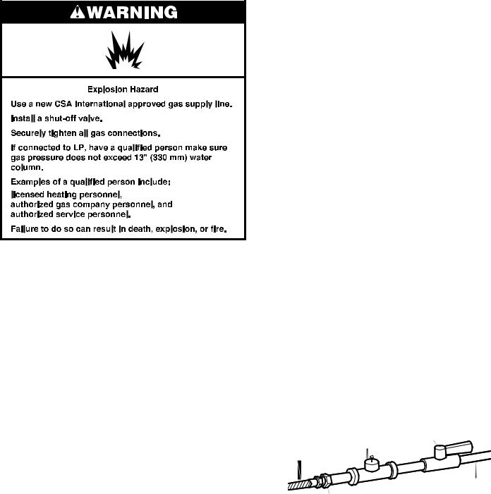
DRYER SAFETY
2

3
INSTALLATION REQUIREMENTS
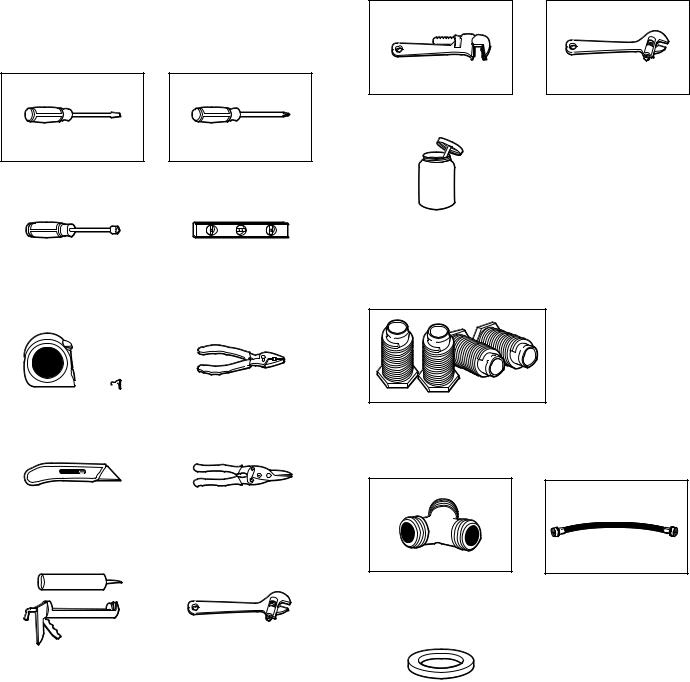
TOOLS AND PARTS
Gather the required tools and parts before starting installation.
Tools needed for all installations:
Flat-blade screwdriver |
|
#2 Phillips screwdriver |
|
|
|
|
|
|
¼" and 5/16" nut driver |
|
Level |
||||
(recommended) |
|
|
||||
|
|
|
|
|
|
|
|
|
|
|
|
|
|
|
|
|
|
|
|
|
Tape measure |
Pliers |
|
|
|
|
|
|
|
Utility knife |
Tin snips (new vent |
|
|
|
installations) |
|
|
|
|
|
|
Caulking gun and |
Adjustable wrench that |
compound (new vent |
opens to 1" (25 mm) or |
installations) |
hex-head socket wrench |
Tools needed for gas installations:
8" or 10" pipe wrench |
8" or 10" adjustable wrench |
|
(for gas connections) |
|
|
Pipe-joint compound resistant to LP gas
Parts supplied (all models):
Leveling legs (4)
Parts supplied (steam models):
“Y” connector |
2' (0.6 m) inlet hose |
|
|
|
|
Rubber washer
Parts package is located in dryer drum. Check that all parts are included.
NOTE: Do not use leveling legs supplied with dryer if installing with a pedestal or a stack kit.
Parts needed: (Not supplied with dryer) ■■Vent clamps
■■Vent elbows and vent work
4
Parts needed (steam models): |
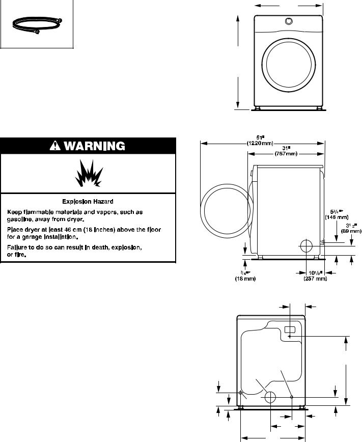
DRYER DIMENSIONS |
|||
|
|
Front view: |
||
|
|
|||
|
|
|
|
|
5' (1.52 m) inlet hose
Additional parts may be required, depending on your installation. Check local codes. Check existing electrical supply and venting. Read “Electrical Requirements” and “Venting Requirements” before purchasing parts.
Optional Equipment: (Not supplied with dryer) Refer to your Use and Care Guide for information about accessories available for your dryer.
383/4" Min.
(984 mm)
39" Max. (990 mm)
27" (686 mm)
LOCATION REQUIREMENTS
You will need:
■■A location allowing for proper exhaust installation. See “Venting Requirements.”
■■A separate 15 or 20 amp circuit for a gas dryer or 30 amp circuit for an electric dryer.
■■If using power supply cord, a grounded electrical outlet located within 2 ft. (610 mm) of either side of dryer. See “Electrical Requirements.”
■■Floor must support dryer weight of 200 lbs. (90.7 kg). Also consider weight of companion appliance.
■■Cold water faucets located within 4 ft. (1.2 m) of the water fill valves, and water pressure of 20–120 psi (138–827 kPa). You may use the water supply for your washer using the supplied “Y” connector and a short hose (which you will need to purchase).
■■Level floor with maximum slope of 1" (25 mm) under entire dryer. If slope is greater than 1" (25 mm), install Extended Dryer Feet Kit, Part Number 279810. If not level, clothes may not tumble properly and automatic sensor cycles may not operate correctly.
■■For garage installation, place dryer at least 18" (460 mm) above floor. If using a pedestal, you will need 18" (460 mm) to bottom of dryer.
■■The dryer must not be installed or stored in an area where it will be exposed to water and/or weather.
IMPORTANT: Do not operate, install, or store dryer where
it will be exposed to water, weather, or at temperatures below 40°F (4°C). Lower temperatures may cause dryer not to
shut off at end of automatic sensor cycles, resulting in longer drying times.
Side view:
* Approx. measurement
Back view:
61/4"
(159 mm)
|
|
|
297/8"* |
|
Water inlet |
(759 mm) |
|
53/4"* |
(Steam Models Only) |
|
|
Vent |
|
31/2"* |
|
(146 mm) |
|
||
|
|
|
(89 mm) |
|
Gas |
|
|
|
|
|
61/8"* |
3/4"* |
14 |
3 |
(156 mm) |
(18 mm) |
/8" |
|
|
(365 mm) |
|
||
|
|
||
|
253/4" |
|
|
|
(654 mm) |
|
* Approx. measurement |
|
|
|
|
NOTE: Most installations require a minimum of 5" (127 mm) clearance behind dryer for exhaust vent with elbow. See “Venting Requirements.”
5
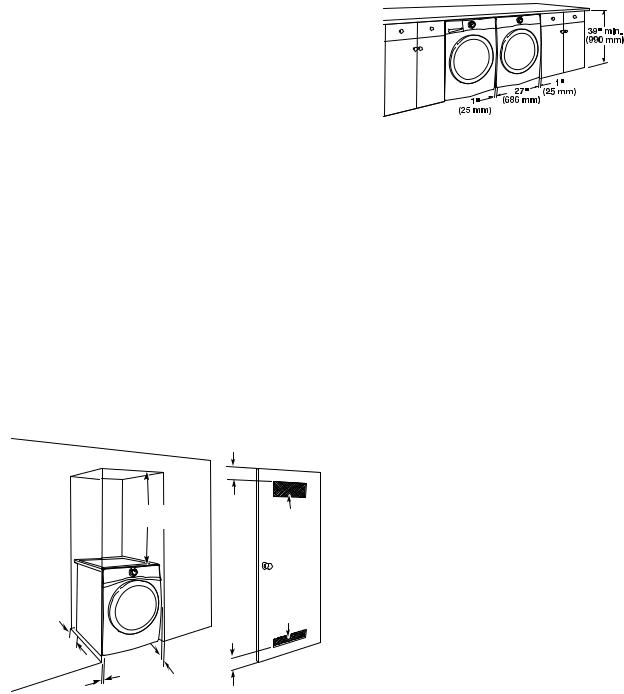
Installation Clearances
For each arrangement, consider allowing more space for ease of installation and servicing; spacing for companion appliances and clearances for walls, doors, and floor moldings. Space must be large enough to allow door to fully open. Add spacing on all sides of dryer to reduce noise transfer. If a closet door or louvered door is installed, top and bottom air openings
in door are required.
Check code requirements. Some codes limit, or do not permit, installation of the dryer in garages, closets, mobile homes, or sleeping quarters. Contact your local building inspector.
NOTE: No other fuel-burning appliance can be installed in the same closet as a dryer.
Installation spacing for recessed area or closet installation
All dimensions show recommended and minimum spacing allowed.
■■Additional spacing should be considered for ease of installation and servicing.
■■Additional clearances might be required for wall, door, floor moldings, dryer venting, and gas line.
■■Additional spacing should be considered on all sides of the dryer to reduce noise transfer.
■■For closet installation with a door, minimum ventilation openings in the top and bottom of the door are required. Louvered doors with equivalent ventilation openings
are acceptable.
■■Companion appliance spacing should also be considered.
Recommended installation clearances (dryer only):
|
3" |
|
18" min. |
(76 mm) |
48 in.2 min. |
(457 mm) |
|
|
|
(310 cm2) |
0" - 5"* |
|
24 in.2 min. |
(0" - 127 mm) |
|
(155 cm2) |
|
|
3" |
0"–5"* |
|
(76 mm) |
|
|
|
(0 mm–127 mm) |
|
|
|
1"* |
1" |
|
(25 mm) |
|
|
(25 mm) |
|
|
|
*0" (0 mm) spacing is allowed for straight back venting only. For steam models only, inlet hose must not be kinked.
Minimum installation clearances (dryer only):
|
Front |
Sides |
Rear |
Top |
Recessed |
NA |
0" (0 mm) |
0" (0 mm)** |
0" (0 mm) |
Closet |
NA |
0" (0 mm) |
0" (0 mm)** |
0" (0 mm) |
**0" (0 mm) spacing is allowed for straight back venting only.
Custom under counter installation:
Mobile home – Additional installation requirements:
This dryer is suitable for mobile home installations. The installation must conform to the Manufactured Home Construction and Safety Standard, Title 24 CFR,
Part 3280 (formerly the Federal Standard for Mobile home construction and Safety, Title 24, HUD Part 280) or Standard CAN/CSA-Z240 MH.
Mobile home installations require:
■■Metal exhaust system hardware, available for purchase from your dealer. For further information, see “Assistance or Service” section in your Use and Care Guide.
■■Special provisions must be made in mobile homes to introduce outside air into dryer. Openings (such as a nearby window) should be at least twice as large as dryer exhaust opening.
For mobile home installation of gas dryers:
■■Mobile Home Installation Hold-down Kit Part Number 346764 is available to order. For further information, see “Assistance or Service” section in your Use and Care Guide.
6
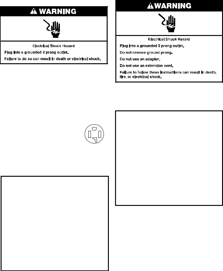
ELECTRIC DRYER POWER HOOKUP – CANADA ONLY
ELECTRICAL REQUIREMENTS
It is your responsibility:
■■To contact a qualified electrical installer.
■■To be sure that the electrical connection is adequate and in conformance with Canadian Electrical Code, C22.1 – latest edition and all local codes. A copy of above codes standard may be obtained from: Canadian Standards Association, 178 Rexdale Blvd., Toronto, ON M9W 1R3 CANADA.
■■To supply the required 4 wire, single phase, 120/240 volt, 60 Hz, AC only electrical supply on a separate 30-amp circuit, fused on both sides of the line. A time-delay fuse or circuit breaker is recommended. Connect to an individual branch circuit.
■■This dryer is equipped with a CSA |
|
|
International Certified Power Cord |
|
|
intended to be plugged into a standard |
|
|
14-30R wall receptacle. The cord is 5 ft. |
|
|
(1.52 m) long. Be sure wall receptacle is |
4-wire receptacle |
|
within reach of dryer’s final location. |
||
(14-30R) |
If using a replacement power supply cord, it is recommended that you use Power Supply Cord Replacement Part Number 8529008.
For further information, please reference service numbers located in “Assistance or Service” section of your Use and Care Guide.
GROUNDING INSTRUCTIONS
■ For a grounded, cord-connected dryer:
This dryer must be grounded. In the event of malfunction or breakdown, grounding will reduce the risk of electric shock by providing a path of least resistance for electric current.
This dryer is equipped with a cord having an equipmentgrounding conductor and a grounding plug. The plug must be plugged into an appropriate outlet that is properly installed and grounded in accordance with all local codes and ordinances.
WARNING: Improper connection of the equipmentgrounding conductor can result in a risk of electric shock. Check with a quali•ed electrician or service representative or personnel if you are in doubt as to whether the dryer is properly grounded. Do not modify the plug provided with the dryer: if it will not •t the outlet, have a proper outlet installed by a quali•ed electrician.
SAVE THESE INSTRUCTIONS
GAS DRYER POWER HOOKUP
ELECTRICAL REQUIREMENTS
■■120 Volt, 60 Hz, AC only, 15or 20amp fused electrical supply is required. A time-delay fuse or circuit breaker is recommended. It is also recommended that a separate circuit serving only this dryer be provided.
GROUNDING INSTRUCTIONS
■ For a grounded, cord-connected dryer:
This dryer must be grounded. In the event of malfunction or breakdown, grounding will reduce the risk of electric shock by providing a path of least resistance for electric current.
This dryer is equipped with a cord having an equipmentgrounding conductor and a grounding plug. The plug must be plugged into an appropriate outlet that is properly installed and grounded in accordance with all local codes and ordinances.
WARNING: Improper connection of the equipmentgrounding conductor can result in a risk of electric shock. Check with a quali•ed electrician or service representative or personnel if you are in doubt as to whether the dryer is properly grounded. Do not modify the plug provided with the dryer: if it will not •t the outlet, have a proper outlet installed by a quali•ed electrician.
SAVE THESE INSTRUCTIONS
7
GAS SUPPLY REQUIREMENTS
GAS TYPE
Natural Gas:
This dryer is equipped for use with natural gas. It is designcertified by CSA International for LP (propane or butane) gases with appropriate conversion.
■■Your dryer must have the correct burner for the type of gas in your home. Burner information is located on the rating plate in the door well of your dryer. If this information does not agree with the type of gas available, contact your dealer or call the phone numbers referenced in the “Assistance or Service” section of your Use and Care Guide.
LP Gas Conversion:
IMPORTANT: Conversion must be made by a qualified technician.
No attempt shall be made to convert the appliance from the gas specified on the model/serial rating plate for use with a different gas without consulting your gas company.
GAS SUPPLY LINE
Option 1 (Recommended Method)
Flexible stainless steel gas connector:
■■If local codes permit, use a new flexible stainless steel gas connector (Design Certified by the American Gas Association or CSA International) to connect your dryer to the rigid gas supply line. Use an elbow and a 3⁄8" flare x 3⁄8" NPT adapter fitting between the stainless steel gas connector and the dryer gas pipe, as needed to prevent kinking.
Option 2 (Alternate Method)
Approved aluminum or copper tubing:
■■Must include 1/8" NPT minimum plugged tapping accessible for test gauge connection, immediately upstream of the gas connection to the dryer. See illustration.
■■½" IPS pipe is recommended.
■■ 3⁄8" approved aluminum or copper tubing is acceptable for lengths under 20 ft. (6.1 m) if local codes and gas supplier permit.
■■If you are using natural gas, do not use copper tubing.
■■Lengths over 20 ft. (6.1 m) should use larger tubing and a different size adapter fitting.
■■If your dryer has been converted to use LP gas, 3⁄8" LP compatible copper tubing can be used. If the total length of the supply line is more than 20 ft. (6.1 m), use larger pipe.
NOTE: Pipe-joint compounds that resist the action of LP gas must be used. Do not use TEFLON®† tape.
■■Must include shut-off valve.
In the U.S.A.:
An individual manual shut-off valve must be installed within six (6) ft. (1.8 m) of the dryer in accordance with the National Fuel Gas Code, ANSI Z223.1. The location should be easy to reach for opening and closing.
In Canada:
An individual manual shut-off valve must be installed in accordance with the B149.1, Natural Gas and Propane Installation Code. It is recommended that an individual manual shut-off valve be installed within six (6) ft. (1.8 m) of the dryer. The location should be easy to reach for opening and closing.
E
C
A
D
B
A.3⁄8" flexible gas connector
B.3⁄8" pipe to flare adapter fitting
C.1⁄8" NPT minimum plugged tapping
D.½" NPT gas supply line
E.Gas shut-off valve
†®TEFLON is a registered trademark of E.I. Dupont De Nemours and Company.
8
 Loading...