


AGS 837
Whirlpool AGS 837, AGS 838, AGS 839, AGS 840, AGS 841 Technical & Service Manual
...
1
WHIRLPOOL
(R404a)
TECHNICAL SERVICE MANUAL
ICE CUBE MAKERS
MODELS:
WHIRLPOOL AGS 836/837
WHIRLPOOL AGS 838/839
WHIRLPOOL AGS 840/841
WHIRLPOOL AGS 842/843
WHIRLPOOL AGS 844/845
WHIRLPOOL AGS 846/847
WHIRLPOOL AGS 848/849
MODULARS:
WHIRLPOOL AGS 850/851 (MODULAR 200)
CAREFULLY READ THE INSTRUCTIONS CONTAINED IN THIS MANUAL SINCE THEY
PROVIDE IMPORTANT INFORMATION RELATIVE TO SAFETY DURING INSTALLATION,
USE, AND MAINTENANCE.
EDITION:
NOVEMBER 2006.
COD: WHP02MTIN.DOC

2
TABLE OF CONTENTS
Introduction
Warnings............................................................................................................................................................3
Description.........................................................................................................................................................4
Operating Principles...........................................................................................................................................5
Specifications
Diagrams of connections and dimensions (undercounter models).....................................................................6
Consumption data, weights, crated dimensions and volumes (undercounter models)........................................8
Technical data (undercounter models).............................................................................................................10
Production Tables............................................................................................................................................11
Delivery & Unpacking
Packing.............................................................................................................................................................13
Rating plate and serial number.........................................................................................................................13
Installation
Recommended placement of unit.....................................................................................................................14
Water and drainage..........................................................................................................................................14
Connecting unit to water source.......................................................................................................................15
Connecting unit to drain...................................................................................................................................15
Electrical connection........................................................................................................................................15
Operation principle
Preliminary check............................................................................................................................................17
Cross check......................................................................................................................................................17
Adjustment
Water level.......................................................................................................................................................18
Water pressure control valve............................................................................................................................18
Pressure control................................................................................................................................................19
Safety pressostat...............................................................................................................................................19
Maintenance and cleaning instructions
Maintenance table............................................................................................................................................20
Water condenser..............................................................................................................................................21
Air condenser...................................................................................................................................................21
Evaporator / water deposit...............................................................................................................................21
Inlet filters........................................................................................................................................................22
Special advice concerning r-404 refrigerant
Troubleshooting
....................................................................................................23
........................................................................................................................................................24

3
INTRODUCTION
Thank you for choosing Whirlpool ice cube makers.
You have purchased one of the most reliable ice-making products on the market today. Carefully read the
instructions contained in this manual since they provide important information relative to safety during
installation, use, and maintenance.
WARNINGS
This appliance should be installed by approved Technical Service Personnel.
This plug should be accessible at all times.
To reduce the risk of electrical shock, ALWAYS disconnect the machine BEFORE cleaning or maintaining
the equipment. Do not attempt to install, service, or modify this machine. Improper use by other than
specially trained technicians is extremely dangerous and may result in a fire or electric shock.
This machine should not be placed outdoors or exposed to rain.
Connect to drinking water mains.
This appliance is not intended for use by young children or infirm persons without supervision.
Young children should be supervised to ensure that they do not play with the appliance.
IMPORTANT!
• DO NOT ATTEMPT TO SERVICE THIS MACHINE AS IT IS DANGEROUS AND COULD
CAUSE SEVERE DAMAGE TO THE UNIT.
•SERVICE SHOULD ONLY BE CARRIED OUT BY TRAINED, CERTIFIED PERSONNEL.
•WE STRONGLY RECOMMEND USING ONLY ORIGINAL REPLACEMENT PARTS
AVAILABLE FROM AN AUTHORIZED DISTRIBUTOR.
•WASTE AND OTHER MATERIAL SHOULD BE DISPOSED OF ACCORDING TO LOCAL
REGULATIONS AND PROCEDURES FOR WASTE DISPOSAL.
•CLEANING AND MAINTENANCE ARE NOT COVERED BY THE WARRANTY.

4
DESCRIPTION
The ice cubes maker is the result of years of experience in this field and the development of a high
technology factory.
Main Features
Storage bin made of polyester strengthened with glass fibre or ABS
•
Stock bin made of high resistance plastic materials
•
Polyurethane insulation injected “IN SITU”
•
Heavy duty door (pat.) except AGS 836/837/838/839 and 850/851.
•
Agitator motor for continuous service
•
Tough cam motor (50 Kg/cm)
•
Safety device and clutch for the water pan preventing its breakage during the upward cycle, (pat.)
•
Machine stoppage and water pan protection during the downward cycle, (pat.)
•
The stock ice is the maximum than it could be thanks to the stop machine system.
•
Low noise
•
High pressure safety pressostats even in air-cooled machine.
•
Large condensers (work well at high ambient temperatures; and reduce cooling water consumption in
•
water-cooled machines).
Clear cubes.
•
Ices Cubes can be adjusted (height and diameter).
•
Easy to maintain and repair.
•
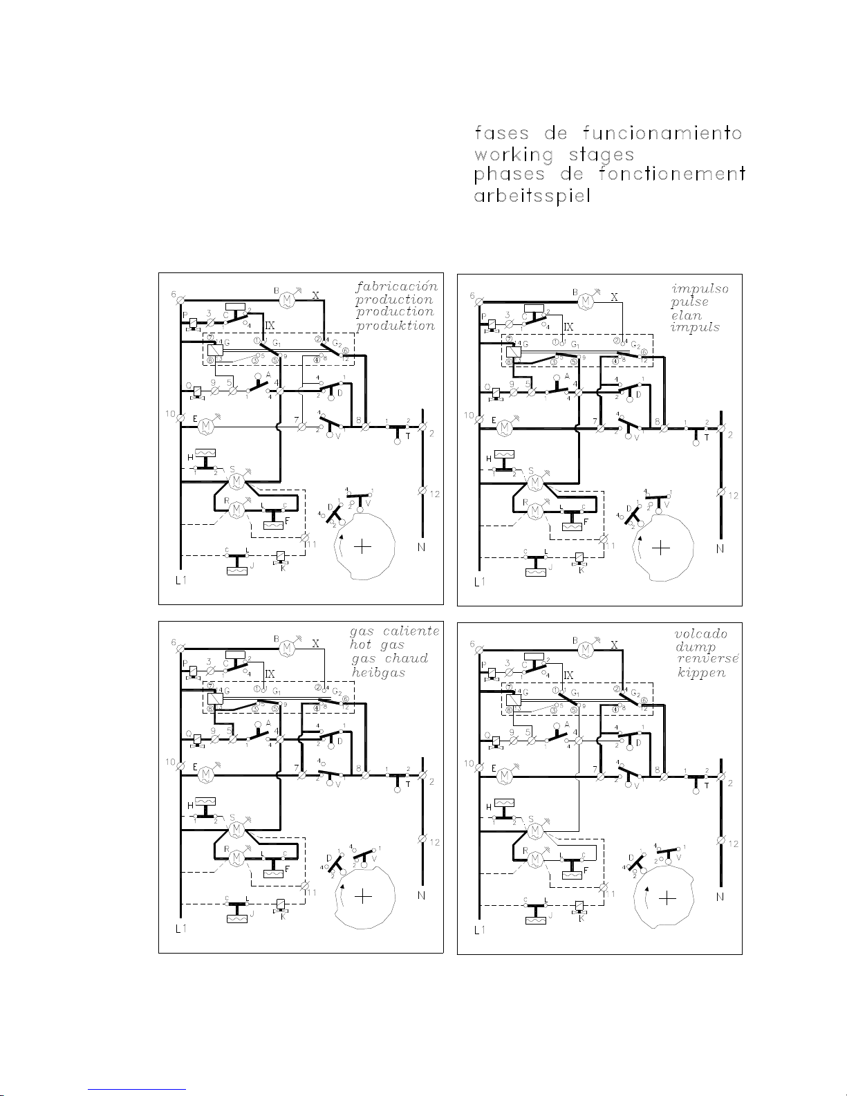
HOW IT WORKS
When the machine is switched on the compressor and the agitator motor start, the water entry valve opens
and allows water into the production pan up to a level where the float makes a micro-switch cut the current
to the valve and so stop water entering the tray. The compressor, controlled by capillaries produces enough
cold in the evaporator to gradually freeze the water around its “fingers”.
When the ice so formed reaches the proper size the paddles of the agitator are stopped and its motor,
suspended, works the end of cycle micro-switch.
This micro-switch connects the relay that starts the cam motor. When the micro-switch has fallen, opens the
hot gas valve and stops the agitator motor. The compressor continues working for another 20”, then stops,
and the agitator motor is connected. The cam motor starts to move downwards, making part of the surplus
water flow to the drain, and dropping the ice cubes, pushed by the ejection plate into the storage bin.
The pan eventually gets back to its initial position and so starts another production cycle.
Once the storage bin is full the pan stops in its downward movement as it touches the cubes, so working the
safety stop micro-switch and switching off the machine. Production will start again as soon as the cubes
which detained it move or are removed.
5
IRLPOOL
WH
6
WHIRLPOOL AGS
7
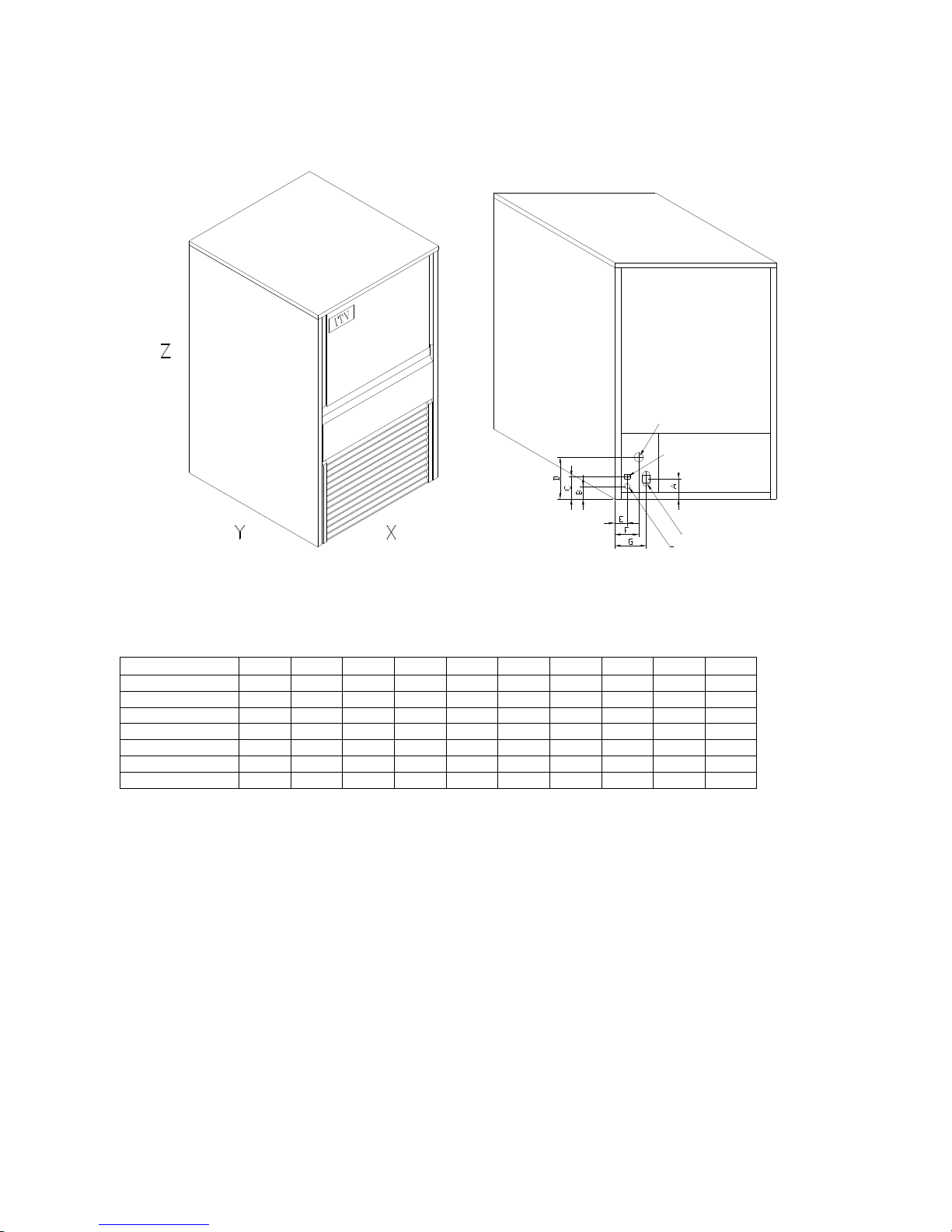
SPECIFICACIONS
Bin drain
Cooling water
Models: WHIRLPOOL AGS 836….849
Water entry
Electrical
connection
* HEIGHT Z REPRESENTS MINIMUM MACHINE HEIGHT. IF LEGS ARE PLACED UNDER MACHINE, THEN ADD
AN EXTRA 80 MM.*
MODEL X Y Z A B C D E F G
WHP AGS 836/837 405 510 690 60 35 65 123 45 65 105
WHP AGS 838/839 405 510 745 60 35 65 123 45 65 105
WHP AGS 840/841 405 510 870 60 35 65 123 45 65 105
WHP AGS 842/843 515 555 870 60 42 74 123 65 75 105
WHP AGS 844/845 595 555 995 60 42 74 123 65 75 105
WHP AGS 846/847 675 555 995 60 42 74 123 65 75 105
WHP AGS 848/849 845 555 995 60 42 74 123 65 75 105
8
850
-
851
WHIRLPOOL AGS
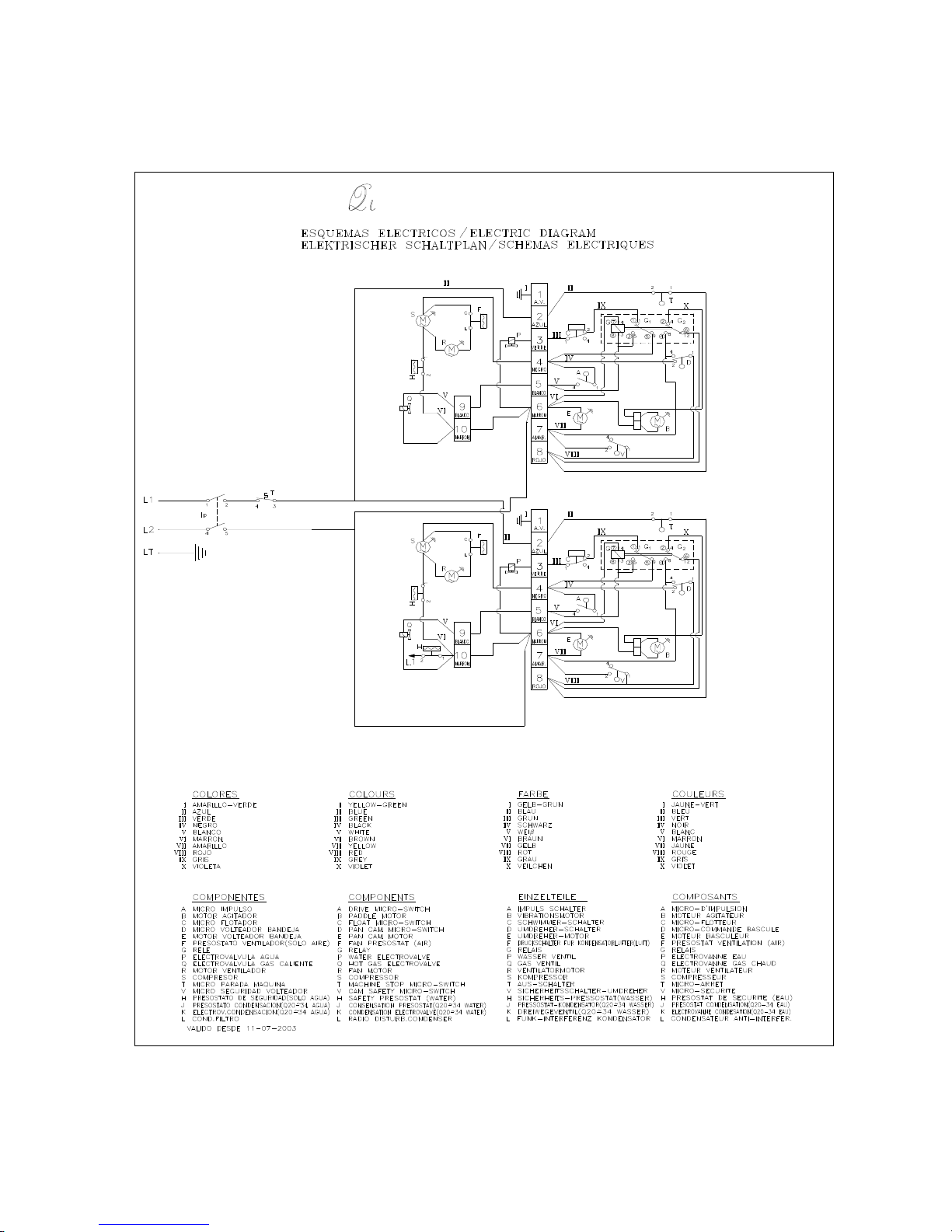
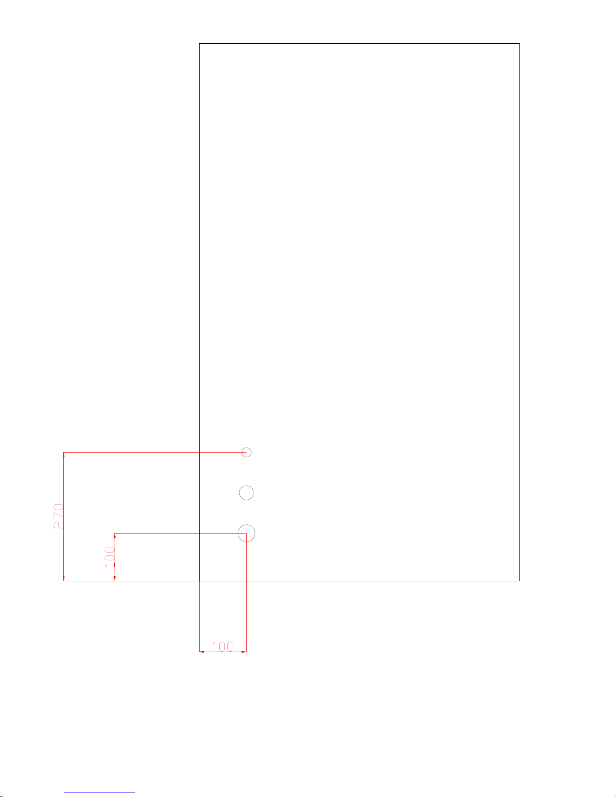
ELECTRICAL CONNECTION
STOCK THERMOSTAT
WATER INLET
 Loading...