

Page 1
Installation, operating and
maintenance instructions
ELECTRIC KETTLES 50 lt
AGB 511/WP
07/2007
037_03_NEW SELECTOR SWITCH
Page 2

037-03 - Electric kettles 50 lt
2
Models and dimensions page 3
General reminders and notes 5
Technical data 5
Construction 6
Laws, technical prescriptions and
directives 6
Special requirements for the installation
site 6
Positioning, installation
and maintenance 6
Positioning 6
Installation 6
Electrical connections and equipotential
bonding 6
Connection to waterworks 7
Commissioning and testing page 7
Maintenance of the appliance 7
Possible failures and their elimination 7
Use and cleaning 8
Warnings and hints for user 8
Instructions for use 8
Filling the jacket 8
Switch on, start of cooking and switch off 8
Cleaning and care of the appliance 8
Daily cleaning 8
Special procedures in case of long
inactivity 8
Special procedures in case of failures 8
How to proceed, if … 9
WEEE Directive 9
Wiring diagrams 10
Warning 11
INDEX
Page 3
037-03 - Electric kettles 50 lt
3
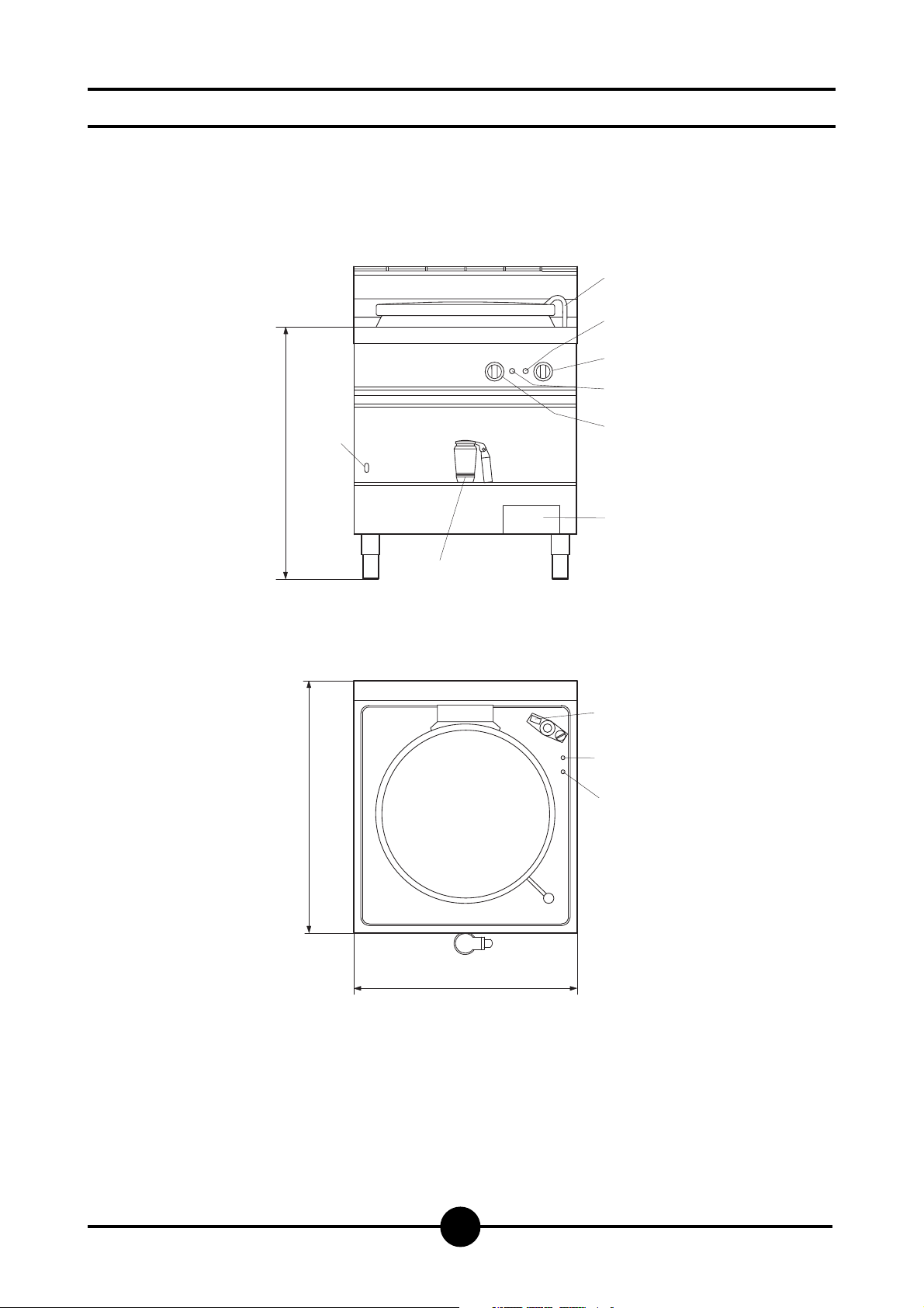
AGB 511/WP
C Hot water connection to 10 mm
E Electrical connection
F Cold water connection to 10 mm
1 Selector
2 Operation light
3 Pressure gauge
4 Cooking vat drainage tap
5 Vat water feed tap
6 Level water jacket
7 Orange warning light
8 Operating thermostat
Models and dimensions
5
2
1
7
C
6
E
4
3
C
8
B
F
A
Page 4
037-03 - Electric kettles 50 lt
4
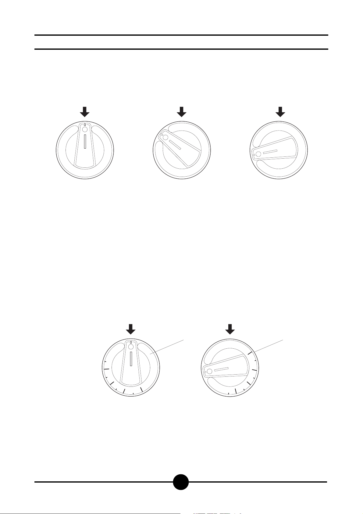
A Position OFF
B Position MAX
Controls
Selector switch
Operating thermostat
0 Off
1 50% power
2 100% power
1
1
2
2
1
2
A B
1
0
4
0
6
0
8
1
0
0
0
0
0
8
0
6
0
4
Page 5
037-03 - Electric kettles 50 lt
5
GENERAL REMINDERS
Read the warnings contained in this manual carefully as
hey provide important information concerning safety duing the installation, use and maintenance of the appliance.
Keep these instructions carefully!
Only personnel trained for its specific use should use the
quipment.
Keep the appliance under control during use.
The appliance should be used only for the purpose for
hich it has been specifically designed; other uses are
mproper and hence dangerous.
During operation surfaces can become hot and require
pecial operation.
Unplug the appliance in case of failures or improper ope-
2 - CHARACTERISTICS OF THE APPLIANCES
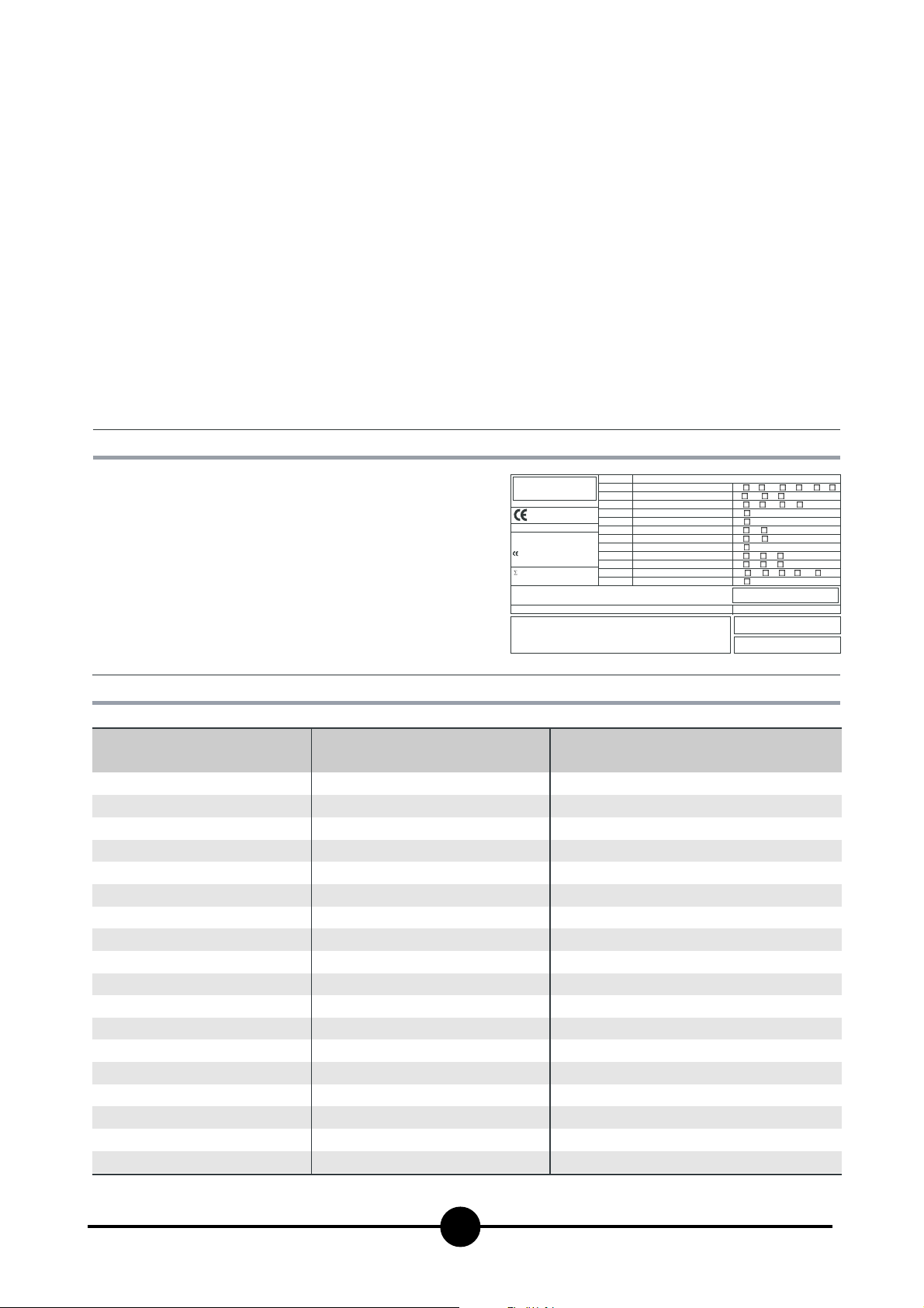
The data plate is located on the rigth hand side of the
control panel and contains all the data needed for connecting
it up to the mains electricity supply.
ration.
- Apply exclusively to a service centre for repairs or maintenance.
- All important information about the appliance required for
technical service is contained in the technical data plate
(see figure 1).
- In the event of technical assistance being required, the
trouble must be described in as much detail as possible,
so that a service technician will be able to understand the
nature of the problem.
- Gloves should be worn to protect the hands during installation and maintenance operations.
Warning!: Follow the fire prevention regulations
very carefully.
CAT/KAT GAS/GAZ G30 G31 G20 G25
II2H3B/P P mbar 30 30 20 -
II2H3+ P mbar 30 37 20--
II2H3+ P mbar 28 37 20 -
TIPO/TYPE
MOD.
ART.
N.
N.
Qn kW
MOD.
V AC kW Hz
THE APPLIANCE MUST BE CONNECTED IN COMPLIANCE WITH THE LAWS IN FORCE
AND INSTALLED IN A WELL-VENTILATED ROOM. READ THE INSTRUCTION MANUALS
BEFORE INSTALLING AND USING THE APPLIANCE.
THE APPLIANCE MUST BE INSTALLED BY QUALIFIED PERSONNEL.
II2ELL3B/P P mbar 50 50 20 20
II2E+3+ P mbar 28 37 20 25
II2H3B/P P mbar 50 50 20 -
I2E P mbar - - 20 -
II2H3+ P mbar 28 37 20 -
I3B/P P mbar 30 30
m3/h
I3+ P mbar 28 37
Predisposto a gas: - Gas preset: - Prevu pour gaz:
Eingestelt für Gas: - Preparado para gas: -
25II2L3B/P P mbar 30 30
--II2H3B/P P mbar 30 30
--
--
Geschuckt voor:
SE FI DK CZ SK SI
IT CH PT
ES IE GB GR
NL
DE
FR BE
AT C H
LU
EE LV LT
EE LV LT
NO MT CY IS HU
CY
MADE IN ITALY
Model
Width (A)
Depth (B)
Height (C)
Vat diameter
Vat height
Total volume
Usable volume
Voltage/Input
Power
Power cable
Hot water connection
Cold water connection
Water pressure
Pressure
mm
mm
mm
mm
mm
lt
lt
kW
mm
mm
kPa
bar
3 - TECHNICAL DATA
AGB 511/WP
800
700
900
400
450
58
50
400 V 3N / 230 V 3
9
2
5 x 1.5 mm
10
10
50 - 300
0.5
/ 4 x 2.5 mm
2
Page 6

037-03 - Electric kettles 50 lt
6
Construction
- Main structure in AISI 430 with 4 adjustable height feet.
- Panels in stainless steel AISI 304, thickness 10-12/10.
- Cooking vat in stainless steel AISI 316, thickness 20/10.
- Chrome-plated brass drainage tap.
- Lid in stainless steel, hinged and spring balanced in all
opening positions.
- Jacket and lining in stainless steel AISI 304, thickness
15-20/10.
- Heating system comprising shielded heating elements
made from “Incoloy-800” alloy with boiler and steam circulation.
- Jacket pressure is controlled by a safety valve set at 0.5
bar; the appliance is equipped with an analogue pressure gauge.
- The cold water connection is 10 mm.
- The hot water connection is 10 mm.
- Safety thermostat to interrupt operation automatically in
case of failures.
- The appliance is equipped with a three-position selec-
tor with three heating functions:
- position “0” Heating not activated
- position “1” Reduced power 50%
- position “2” Full power 100%
Laws, technical prescriptions and directives
When installing the appliance it is necessary to follow and
comply with the following regulations:
- current regulations on the matter;
- any hygienic-sanitary regulations concerning cooking
environments;
- municipal and/or territorial building regulations and fire
prevention prescriptions;
- current accident prevention guidelines;
- electricity board regulations concerning safety;
- the regulations of the electrical power supply company
or agency;
- any other local prescriptions.
Special requirements for the installation site
- The room in which the appliance is to operate must be
well ventilated.
- In addition, it is good policy to locate the appliance under an extractor hood so that cooking vapours can be
removed rapidly and continuously.
- Current regulations require the installation of a multiple
pole switch between the appliance and the electrical
power supply; the switch must have a contact gap of
least 3 mm on each pole.
- This appliance requires two water connections: one for
hot and one for cold water. Each line must be fitted with
an on-off valve.
Warning! : The electrical isolating switch and the
water shutoff valves must both be located near to the
appliance, within easy reach for the user.
Postioning
Remove all the packaging and check that the appliance is
in perfect conditions. In case of visible damage, do not connect the appliance and notify the sales point immediately.
Remove the PVC protection from the panels.
Dispose of packaging according to regulations. Generally
material is divided according to composition and should
be delivered to the waste disposal service.
There are no special instructions regarding distances from
other appliances or walls, however it is advisable to maintain a sufficient distance to allow any servicing operations
to be performed. In the event the appliance should be installed in direct contact with inflammable walls, it is advisable to fit suitable heat insulation.
The appliance must stand level. Small differences in level
can be eliminated by screwing or unscrewing the adjustable feet: A significantly uneven or sloping stance can affect the operation of the appliance adversely.
Installation
Warning! : Only qualified technicians must perform
the installation, maintenance and test of the appliance.
Warning! : Before connecting any parts of the appliance to supplies, make sure that the latter is equivalent the requirements stated in the technical data plate,
if the appliance has been designed for these supplies.
Electrical connections and equipotential bonding
Warning! : The appliance is supplied to operate
according to the power supply indicated on the data
plate.
As mentioned, the appliance must be connected to the
power supply by way of a multiple pole main isolating switch and protection device that must be proportioned to the
power of the appliance (1 mA per kW of rated power).
The earthing system must be efficient.
As this appliance is type X equipment (delivery without
power cable and plug), the cable and other hardware needed to make the connection to the electrical power supply
must be provided by the installer.
The power cable shall be of the kind described in the paragraph “Technical data" and shall be resistant to oil.
The power terminal board can be reached by removing
the lower front panel (unloose the screws). The cable fastener is on the lower right-hand side.
The cable must be fed in from beneath the clamp. The individual wires are then fastened to the corresponding terminals of the terminal board. The earth wire must be longer than the other wires, so that in the event of the cable
being jerked or the clamp broken, the live wires will disconnect first. Lock the cord fastener.
The appliance must incorporate an equipotential system.
POSITIONING, INSTALLATION AND MAINTENANCE
Page 7

037-03 - Electric kettles 50 lt
7
Connect the terminal on the lower right-hand side marked
with the international symbol a connector with a nominal
cross section <10 mm
2
. All the appliances installed and the
earth system of the building shall be connected like this.
Connection to waterworks
Water inlet pressure must be between 50 and 300 kPa,
otherwise install a pressure regulator on the line before
the appliance.
Install a cut-off valve for each supply on the line before
the appliance.
Water connections to 10 mm are fitted in the lower part on
the right-hand side of the appliance.
Make connections according to regulations currently in
force.
Commissioning and testing
Once all the connections have been made, the appliance
and the overall installation must be checked following the
directions given in this manual.
Check in particular:
- that the protective film has been removed from the external surfaces;
- that the lower front panel removed for the electrical connection of the appliance has been fitted back into position;
- that connections have been made in accordance with
the requirements and directions indicated in this manual;
- that all safety requirements in current standards, statutory regulations and directives have been met;
- that the water connections are leak-free;
- that the electrical connection has been performed ac-
cording to standards.
In addition, check that once the appliance has been installed, the power cord is neither subject to stretch nor in
contact with nor surfaces.
Now proceed to light the appliance as directed in the instructions for use.
While the appliance is in use, voltage should not differ
from the nominal voltage more than +/- 10%.
The test report must be completed in full and submitted to
the customer who should then sign in acceptance. With
effect from this moment, the appliance is covered by the
manufacturer’s warranty.
Maintenance of the appliance
Warning! : All maintenance operations shall only
be performed by a technically qualified service centre!
To ensure correct and safe operation, the appliance must
be inspected and serviced at least once a year only.
Maintenance includes also controlling the components
and tear of pipes, feeding pipes, electrical components
etc.
It is advisable to replace worn components during maintenance operations to avoid the need for other maintenance
calls and unexpected failures.
It is also advisable to apply for a maintenance contract
with the customer.
Possible failures and their elimination
Warning! : Only technically qualified service
centres can perform the operations described below!
Warning! : Before resetting the safety thermostat, it is always necessary to eliminate the problem
causing its activation!
Page 8

037-03 - Electric kettles 50 lt
8
Warnings and hints for user
This manual contains all the instructions required for a proper
and safe use of our appliances.
Keep the manual in a safe place for future consultation!
This appliance is for catering use, hence they must be used
only by trained kitchen staff.
The appliance must always be kept under control during use.
Warning! : The manufacturer shall not be held responsible for injuries or damage due to the non-compliance with safety rules or an improper use of the appliance by the operator.
Some improper operating conditions may even be caused by
an improper use of the appliance, therefore it is important to
train personnel properly.
All the installation and maintenance operations must be
performed by fitters who are members of an official register.
Respect the periods required for maintenance. With this is
mind, customers are recommended to sign a service agreement.
In case of failures concerning the appliance, all outputs
(electrical power supply and water) must be cut off instantly.
In case of recurrent failures, contact a service technician.
Intruction for use
Before cooking with the appliance for the first time, wash
the interior of the cooking vat thoroughly.
Warning! : Fill the cooking vat up to a maximum
of 40 mm under the overflow border, according to the
maximum level mark, including the food to be cooked.
Warning! : Before filling the vat, always check
that the drainage tap is closed.
Filling the jacket
Warning! : The water level inside the jacket must
be controlled each time before switching on the appliance.
Warning! : It is advisable to use softened water
to fill the jacket.
Open the level tap on the front of the appliance.
Unscrew the filling cap on the safety valve unit. The latter
is on the right-hand side of the appliance (see figure “View
of appliance”).
Add softened water (the capacity of the jacket is stated in
the paragraph “Technical Data”).
When water comes out of the level tap, close it and screw
back on the safety unit cap.
Switching on, start cooking and switching off
Fill the vat with hot or cold water, according to need, using
the tap that the appliance is equipped with.
The appliance has a three-position selector to start
cooking functions (see figure “Controls").
Here is a list of the procedures for a safe and correct use
of the appliance.
Energising the unit:
Connect the appliance by turning on the main switch installed before it.
Start of cooking:
Turn the selector from position “0” to one of the heating
positions according to cooking requirements.
Generally cooking starts with the selector on position “2”;
once the vat has reached cooking temperature the selector is turned back to “1” to maintain the cooking temperature.
The heating mode of the appliance is indicated by the
green operation light.
End of cooking
Turn the selector back to “0”.
Cleaning and care of the appliance
Do not use aggressive substances or abrasive detergents
when cleaning the stainless steel components.
Avoid using metal pads of the steel parts as they may
cause rust. For the same reason, avoid contact with materials containing iron.
Do not use sandpaper or abrasive paper for cleaning; in
special cases use a powder pumice stone.
In case of particularly resistant dirt, it is advisable to use
abrasive sponges (e.g. Scotch-Brite).
It is advisable to clean the appliance only once it has cooled down.
Daily cleaning
Warning! : When cleaning the appliance never
use direct jets of water to prevent infiltration of the liquid and damage to components.
Clean the cooking vat with water and a detergent, rinse
thoroughly and dry well with a soft cloth.
External surfaces should be washed down using a sponge, and hot water with a suitable proprietary cleaner addend.
Rinse always thoroughly and dry with a soft cloth.
Special procedures in case of prolonged inactivity
If the appliance is to stand idle for any length of time (e.g.
holidays or seasonal closing), it must be cleaned thoroughly, leaving not traces of food or dirt.
Leave the lid open so that air can circulate inside the vat.
For added care after cleaning, the external surfaces can
be protected by applying a proprietary metal polish.
Be absolutely sure to shut off all utilities (electrical power
supply and water).
Air the room appropriately.
Special procedures in case of failures
If the appliance should not work properly during use, turn
it off immediately and close or cut off all supplies (electrical power supply and water).
Apply to a service centre for help.
USE AND CLEANING
Page 9
How to proceed, if …
Warning! : Problems and failures may occur
even when the appliance is used properly. Here is a list
of the mist probably situations and controls that the
operator should perform to avoid applying to a service
centre unnecessarily.
If the problem is not solved after the necessary controls, turn off the appliance immediately, unplug it, cut
off any supplies and apply to a service centre.
037-03 - Electric kettles 50 lt
9
… the vat contents do not heat up:
- check that the power ON/OFF switch installed before
the appliance is on;
- otherwise turn off the appliance and apply to a service
centre, as the safety thermostat may have been activated due to an excess of temperature in the cooking vat.
This occurs especially when the appliance is turned on
and the vat and/or the jacket is/are empty.
The manufacturer shall not be held responsible nor
has any warranty commitments for damage caused
by non-compliance with prescriptions or by installation not in conformity with instructions.
The same applies in case of improper use or different application by the operator.
THE 2002/96/EC DIRECTIVE (WEEE):
information to users
This informational note is meant only for owners
of equipment marked with the symbol shown in
Fig. A on the adhesive label featuring the technical specifications applied on the actual pro-
duct (the label also giving the serial number).
This symbol indicates that the product is classified, according to the regulations in force, as an item of electrical
and electronic equipment and conforms to EU Directive
2002/96/EC (WEEE) meaning that, at the end of its service
life, it must be treated separately from domestic waste,
i.e. it must be handed in free of charge to a separate waste electrical and electronic equipment collection centre
or returned to the reseller when buying a new equivalent
item of equipment.
The user is responsible for delivering the unit at the end of
its life to the appropriate collection facilities. Failure to do
so shall result in the user being subject to the penalties
prescribed by the legislation in force on waste.
Suitable separated collection so that the unit no longer
used can be sent off for environmentally compatible recycling, treatment and disposal helps avoid possible negative effects on the environment and on health and facilitates the recycling of the product's component materials.
For more detailed information on available collection systems, contact the local waste disposal service or the
shop you purchased the unit from.
Producers and importers fulfil their responsibility for environmentally compatible recycling, treatment and disposal
both directly and by joining a collective scheme.
Page 10
2 4 6
037-03 - Electric kettles 50 lt
10
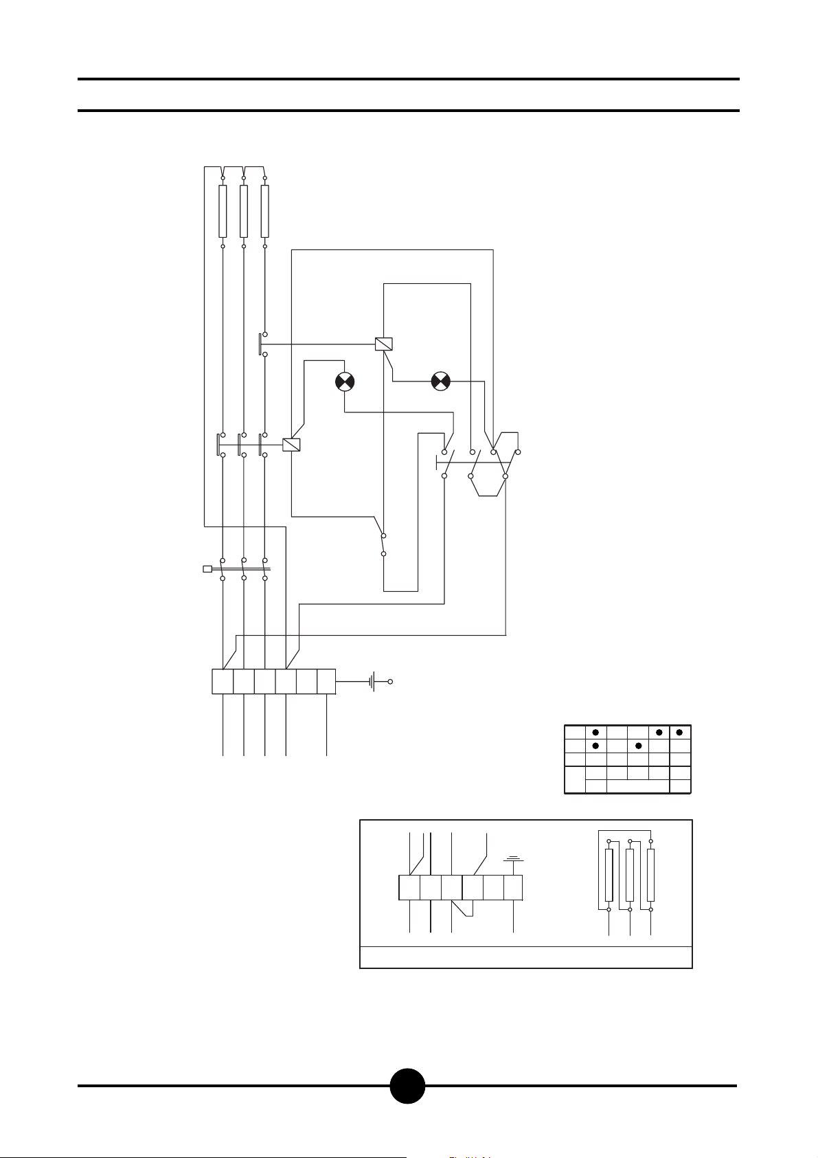
Wiring diagrams
L1 Green operation light Max.
TS Safety thermostat
C1 Electromagnetic switch
L2 Green operation light Min.
TL Working thermostat
SE Three position selector/switch
R1 Heating element
mA Line terminal board
Rm Relay for Min
L2 Yellow operation light
1 3 5
R1
RM
TS
123456
mA
L1
L2
L3
400V 3N
C1
N
PE
L1
TL
P3
L2
5
314
SE
P1
P2
2
1
SE
0
P3
P1
13 425
P2
123456
mA
L1
L2
L3
230V 3
2 4 6
R1
1 3 5
PE
Page 11

037-03 - Electric kettles 50 lt
11
WARNING
THE MANUFACTURER CANNOT BE HELD RESPONSIBLE
FOR ANY INACCURACIES IN THIS BOOKLET DUE TO
COPYING OR PRINTING ERRORS.
DUE TO ITS POLICY OF CONTINUAL PRODUCT IMPROVEMENT, THE MANUFACTURER RESERVES THE RIGHT
TO MAKE ANY CHANGES DEEMED NECESSARY.
THE MANUFACTURER CANNOT BE HELD RESPONSIBLE IF THE INSTRUCTIONS CONTAINED IN THIS MANUAL ARE NOT OBSERVED.
WHIRLPOOL EUROPE srl
V.le Guido Borghi, 27
I – 21025 Comerio – VA
 Loading...