


Gas Fired
Residential
Combi Boiler
Wall Mount Models
INSTALLATION / START-UP
MAINTENANCE / PARTS
WARRANTY
Models
WBRCNG140W
WBRCLP140W
Heat Exchanger Bears the ASME “H” Stamp
NOTICE: Westinghouse reserves the right to make product changes or updates without notice and will not be held liable for typographical errors in literature.
NOTE TO CONSUMER: PLEASE KEEP ALL INSTRUCTIONS FOR FUTURE REFERENCE.
The surfaces of these products contacted by consumable water contain less than 0.25% lead by weight, as required by the Safe Drinking Water Act, Section 1417.
IF THE INFORMATION IN THIS MANUAL IS NOT FOLLOWED EXACTLY, A FIRE OR EXPLOSION MAY RESULT, CAUSING PROPERTY DAMAGE, PERSONAL INJURY, OR LOSS OF LIFE. DO NOT STORE GASOLINE OR OTHER FLAMMABLE VAPORS AND LIQUIDS IN THE VICINITY OF THIS OR ANY OTHER APPLIANCE.
WHAT TO DO IF YOU SMELL GAS
Do not try to light any appliance.
Do not touch any electrical switch.
Do not use any phone in your building.
Immediately call your gas supplier from a neighbor’s phone. Follow the gas supplier’s instructions.
If you cannot reach your gas supplier, call the fire department. Installation and service must be provided by a qualified installer, service agency, or the gas supplier.
WHL-012 REV. 12.17.14

2
WHL-012 REV. 12.17.14
3
The following defined terms are used throughout this manual to bring attention to the presence of hazards of various risk levels, or to important product information.
DANGER indicates an imminently hazardous situation which, if not avoided, will result in death or serious injury.
WARNING indicates a potentially hazardous situation which, if not avoided, could result in death or serious injury.
CAUTION indicates a potentially hazardous situation which, if not avoided, may result in minor or moderate injury.
CAUTION used without the safety alert symbol indicates a potentially hazardous situation which, if not avoided, may result in property damage.
NOTICE
NOTICE is used to address practices not related to personal injury.
SAFETY INSTRUCTIONS
SAFETY INSTRUCTIONS (or equivalent) signs indicate specific safety related instructions or procedures.
NOTE: Contains additional information important to a procedure.
WHL-012 REV. 12.17.14
4
FOREWORD
This manual is intended to be used in conjunction with other literature provided with the appliance. This includes all related control information. It is important that this manual, all other documents included with this system, and additional publications including the National Fuel Gas Code, ANSI Z223.1-2002, be reviewed in their entirety before beginning any work.
Installation should be made in accordance with the regulations of the Authority Having Jurisdiction, local code authorities, and utility companies which pertain to this type of water heating equipment.
Authority Having Jurisdiction (AHJ) – The Authority Having Jurisdiction may be a federal, state, local government, or individual such as a fire chief, fire marshal, chief of a fire prevention bureau, labor department or health department, building official or electrical inspector, or others having statutory authority. In some circumstances, the property owner or his/her agent assumes the role, and at government installations, the commanding officer or departmental official may be the AHJ.
NOTE: Westinghouse reserves the right to modify product technical specifications and components without prior notice.
FOR THE INSTALLER
This manual must only be used by a qualified heating installer/service technician. Read all instructions in this manual before installing. Perform steps in the order given. Failure to comply could result in substantial property damage, severe personal injury, or death.
This appliance must be installed by qualified and licensed personnel. The installer should be guided by the instructions furnished with the appliance, and with local codes and utility company requirements. In the absence of local codes, preference should be given to the National Fuel Gas Code, ANSI Z223.1-2002.
INSTALLATIONS MUST COMPLY WITH:
Local, state, provincial, and national codes, laws, regulations and ordinances.
The latest version of the National Fuel Gas Code, ANSI Z223.1, from American Gas Association Laboratories, 8501 East Pleasant Valley Road, Cleveland, OH 44131.
In Canada – CGA No. B149 (latest version), from Canadian Gas Association Laboratories, 55 Scarsdale Road, Don Mills, Ontario, Canada M3B 2R3. Also, Canadian Electrical Code C 22.1, from Canadian Standards Association, 5060 Spectrum Way, Suite 100, Mississauga, Ontario, Canada L4W 5N6.
Code for the installation of Heat Producing Appliances (latest version), from American Insurance Association, 85 John Street, New York, NY 11038.
The latest version of the National Electrical Code, NFPA No. 70.
NOTE: The gas manifold and controls met safe lighting and other performance criteria when the appliance underwent tests specified in ANSI Z21.13 – latest edition.
The hydronic supply and return connections of these products are for installation in closed loop systems ONLY! Use of this product in any manner other than described in this manual may result in premature product failure, substantial property damage, severe personal injury, or death. Damage or failure of this product (or the system in which it is installed) due to unauthorized use IS NOT COVERED BY WARRANTY.
TABLE OF CONTENTS |
|
|
PART 1 |
– ITEMS SHIPPED WITH THE APPLIANCE ................................................................................................................. |
7 |
PART 2 |
– SAFETY REGULATIONS ........................................................................................................................................... |
8 |
A. OPERATION AND INSTALLATION WARNINGS ....................................................................................................................... |
8 |
|
B. IMPROPER COMBUSTION ....................................................................................................................................................... |
9 |
|
C. GAS.......................................................................................................................................................................................... |
10 |
|
D. WHEN SERVICING THE APPLIANCE..................................................................................................................................... |
10 |
|
|
|
WHL-012 REV. 12.17.14 |
|
5 |
E. WATER QUALITY .................................................................................................................................................................... |
10 |
F. FREEZE PROTECTION ........................................................................................................................................................... |
10 |
PART 3 – TECHNICAL SPECIFICATIONS ............................................................................................................................... |
11 |
PART 4 – PREPARE APPLIANCE LOCATION ........................................................................................................................ |
13 |
A. UNCRATING THE APPLIANCE ............................................................................................................................................... |
13 |
B. BEFORE LOCATING THE APPLIANCE .................................................................................................................................. |
14 |
C. LEVELING................................................................................................................................................................................ |
15 |
D. CLEARANCES FOR SERVICE ACCESS ................................................................................................................................ |
15 |
E. RESIDENTIAL GARAGE, CLOSET, AND ALCOVE INSTALLATIONS.................................................................................... |
16 |
F. EXHAUST VENT AND INTAKE PIPE....................................................................................................................................... |
16 |
G. PREVENT COMBUSTION AIR CONTAMINATION ................................................................................................................. |
16 |
H. REMOVING A APPLIANCE FROM A COMMON VENT SYSTEM........................................................................................... |
17 |
I. WALL-MOUNTING THE APPLIANCE ....................................................................................................................................... |
18 |
J. FLOW RESTRICTOR................................................................................................................................................................ |
18 |
PART 5 – VENTING................................................................................................................................................................... |
20 |
A. INTAKE PIPE AND EXHAUST VENT GUIDELINES ................................................................................................................ |
20 |
B. APPROVED VENT MATERIALS .............................................................................................................................................. |
21 |
C. ALLOWED COMBINED VENT LENGTHS ............................................................................................................................... |
22 |
D. TIGHTENING APPLIANCE COLLAR TO EXHAUST VENT AND INTAKE PIPE ..................................................................... |
23 |
E. VENT TERMINATION .............................................................................................................................................................. |
24 |
1. Two Pipe Roof and Sidewall Vent Terminations ..................................................................................................................... |
24 |
2. Direct Vent, Optional Horizontal and Vertical Vent Kits ......................................................................................................... |
25 |
3. Screen Installation..................................................................................................................................................................... |
25 |
PART 6 – INSTALL THE CONDENSATE DRAIN ..................................................................................................................... |
26 |
PART 7 – GAS PIPING.............................................................................................................................................................. |
27 |
A. GAS PIPE SIZING TABLES ..................................................................................................................................................... |
27 |
1. Gas Pipe Sizing.......................................................................................................................................................................... |
27 |
2. Natural Gas Pipe Sizing ............................................................................................................................................................ |
27 |
3. LP (Liquid Propane) Gas Pipe Sizing....................................................................................................................................... |
28 |
B. GAS CONNECTION REQUIREMENTS ................................................................................................................................... |
28 |
PART 8 – WATER PIPING ........................................................................................................................................................ |
29 |
A. GENERAL PLUMBING CONNECTION GUIDELINES ............................................................................................................. |
29 |
B. DHW PIPING............................................................................................................................................................................ |
31 |
C. CENTRAL HEATING PIPING SYSTEM WATER PIPING METHODS ..................................................................................... |
31 |
D. CH AND DHW PRESSURE RELIEF VALVES ......................................................................................................................... |
35 |
PART 9 – CONNECT ELECTRICAL POWER / INITIAL STARTUP ......................................................................................... |
35 |
A. GENERAL OPERATING CONDITIONS ................................................................................................................................... |
36 |
B. WIRING INFORMATION .......................................................................................................................................................... |
36 |
C. DIP SWITCHES ....................................................................................................................................................................... |
36 |
PART 10 – OPERATING SYSTEM INSTRUCTIONS................................................................................................................ |
42 |
A. CONTROL PANEL ................................................................................................................................................................... |
42 |
|
WHL-012 REV. 12.17.14 |
|
6 |
B. LCD DISPLAY DESCRIPTIONS .............................................................................................................................................. |
42 |
C. START-UP SEQUENCE .......................................................................................................................................................... |
42 |
D. CHANGING THE DHW SET-POINT ........................................................................................................................................ |
43 |
E. CHANGING THE TEMPERATURE INDICATOR ..................................................................................................................... |
43 |
F. CHANGING THE CH SET-POINT ............................................................................................................................................ |
43 |
G. STORAGE MODE .................................................................................................................................................................... |
44 |
H. STATUS DISPLAY MODE ....................................................................................................................................................... |
44 |
I. INSTALLER MODE.................................................................................................................................................................... |
45 |
J. ERROR MODE ......................................................................................................................................................................... |
47 |
K. ERROR TREE ANALYSIS........................................................................................................................................................ |
50 |
1. FLAME DETECTION................................................................................................................................................................... |
50 |
2. GAS DETECTION ....................................................................................................................................................................... |
50 |
3. APS / BURNER OVERHEAT LIMIT / CONDENSATE BLOCK SWITCH ................................................................................... |
51 |
4. DHW / OP / CH OVERHEAT / EXHAUST OVERHEAT SENSORS............................................................................................ |
51 |
L. OUTDOOR TEMPERATURE MODE (OPTIONAL)................................................................................................................... |
51 |
M. 0-10 VOLT INPUT.................................................................................................................................................................... |
52 |
PART 11 – START-UP PREPARATION.................................................................................................................................... |
53 |
A. CHECK / CONTROL WATER CHEMISTRY............................................................................................................................. |
53 |
B. CHECK FOR GAS LEAKS ....................................................................................................................................................... |
53 |
C. FILL AND TEST WATER SYSTEM .......................................................................................................................................... |
54 |
D. PURGE AIR FROM CH AND INTERNAL STORAGE TANK .................................................................................................... |
55 |
E. PURGE AIR FROM DHW SYSTEM ......................................................................................................................................... |
55 |
F. CHECK THERMOSTAT CIRCUIT(S) ....................................................................................................................................... |
55 |
G. CONDENSATE REMOVAL ...................................................................................................................................................... |
56 |
H. FINAL CHECKS BEFORE STARTING APPLIANCE................................................................................................................ |
56 |
I. ADJUSTING GAS PRESSURE AT THE APPLIANCE............................................................................................................... |
56 |
J. SETTING AND VERIFYING THE COMBUSTION SETTING .................................................................................................... |
57 |
PART 12 –INSTALLATION AND START-UP CHECKLIST ...................................................................................................... |
58 |
PART 13 – TROUBLESHOOTING ............................................................................................................................................ |
59 |
PART 14 – ANNUAL MAINTENANCE PROCEDURES ............................................................................................................ |
60 |
REPLACEMENT PARTS ................................................................................................................................................................ |
66 |
Limited Warranty for Combination Appliances........................................................................................................................... |
69 |
START-UP REPORT....................................................................................................................................................................... |
71 |
MAINTENANCE REPORT .............................................................................................................................................................. |
72 |
MAINTENANCE NOTES................................................................................................................................................................. |
75 |
CUSTOMER INSTALLATION RECORD FORM ............................................................................................................................. |
76 |
WHL-012 REV. 12.17.14

7
PART 1 – ITEMS SHIPPED WITH THE APPLIANCE
|
ITEM |
DESCRIPTION |
QUANTITY |
|
|
Wall Hung Combi Boiler |
|
1 |
|
|
|
|
|
|
|
Installation and User’s |
|
|
|
|
Information Manuals, H2 |
|
1 Each |
|
|
Document |
|
|
|
|
|
|
|
|
|
Condensate Hose |
|
1 |
|
|
|
|
|
|
|
CH Pressure Relief Valve |
|
|
|
|
With ¾” X 1” Bushing |
|
1 Each. |
|
|
(CH Line ¾” 30 psi) |
|
|
|
|
|
|
|
|
|
Vent Screens (3”) |
|
2 Screens |
|
|
|
|
|
|
|
Outdoor Sensor with |
|
1 |
|
|
Screws and Anchors |
|
|
|
|
|
|
|
|
|
|
|
|
|
|
3” CPVC |
|
6” Length |
|
|
|
|
|
|
|
½” X ¾” Bell Coupling |
|
1 |
|
|
for Gas Line |
|
|
|
|
|
|
|
|
|
|
|
|
|
|
Spare Parts Kit |
|
1 |
|
|
(Gaskets and O-Rings) |
|
|
|
|
|
|
|
|
|
|
|
|
|
|
Anchors and Wall Mounting |
|
1 |
|
|
Bracket |
|
|
|
|
|
|
|
|
|
|
|
|
|
|
Blue Flow Restrictor |
|
1 |
|
|
(Limits Flow to 4.5 GPM) |
|
|
|
|
|
|
|
|
|
|
|
|
|
WHL-012 REV. 12.17.14
8
OPTIONAL PARTS (Not Included)
ITEM |
|
DESCRIPTION |
QUANTITY |
PART NUMBER |
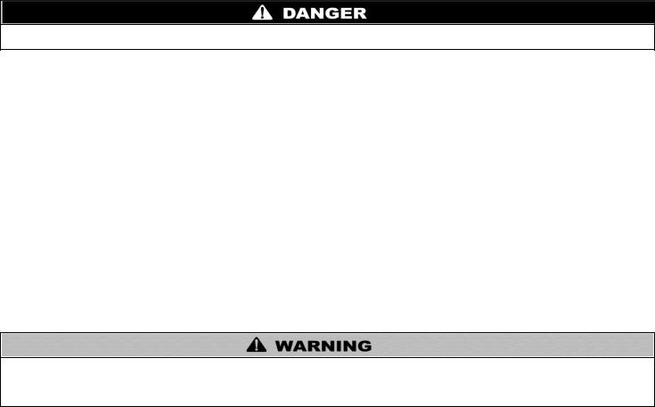
Threaded 1” CH Tankless |
|
|
|
|
Isolation Valves |
|
|
2 |
7850P-089 |
(Without Pressure Relief Valve) |
|
|
|
|
|
|
|
|
|
Threaded ¾” DHW Tankless |
|
|
|
|
Isolation Valves |
|
|
2 |
7850P-090 |
(With Pressure Relief Valve) |
|
|
|
|
|
|
|
|
|
Vent Screens (2” Mesh) |
|
|
2 Screens |
7850P-088 |
|
|
|
|
|
Table 1 – Items Included with the Appliance |
|
|
|
|
PART 2 – SAFETY REGULATIONS
A. OPERATION AND INSTALLATION WARNINGS
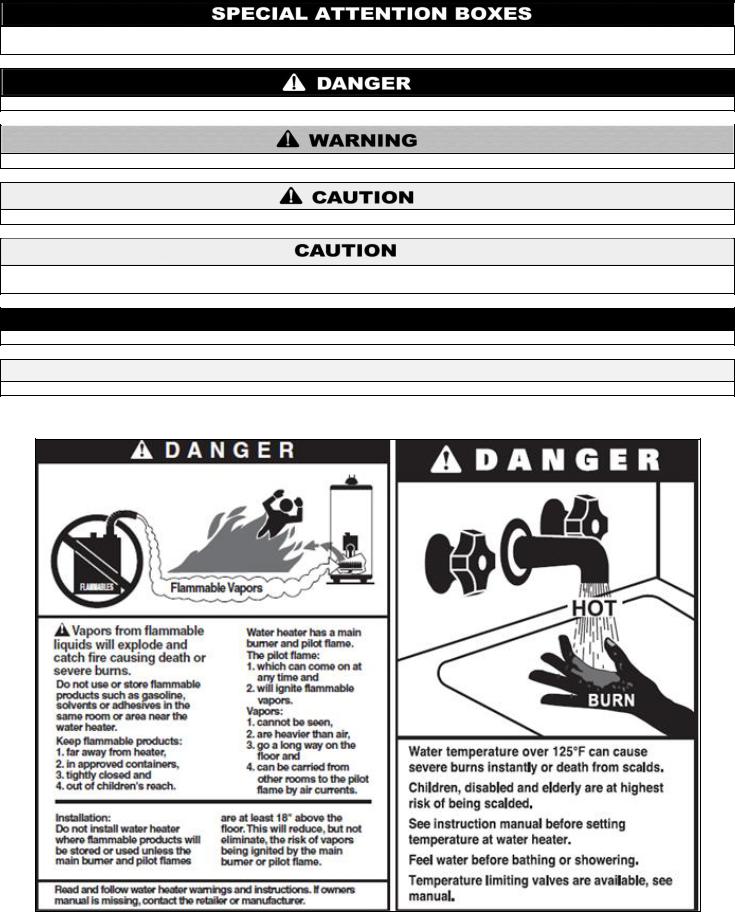
To avoid serious injury or death, read, understand, and follow all the precautions listed here.
Vapors from flammable liquids will explode and can cause a fire, resulting in personal injury or death. The appliance has a burner that can come on at any time and ignite vapors. DO NOT use or store flammable liquids around the appliance.
Improper venting can cause a build-up of carbon monoxide. Breathing carbon monoxide can result in brain damage or death. DO NOT operate the appliance unless it is properly vented to the outside and has an adequate fresh air supply for safe operation. Inspect the exterior exhaust gas outlet port and fresh air inlet port on a regular basis to ensure they are functioning properly.
A concentration of carbon monoxide as small as .04% (400 parts per million) in the air can be fatal. When making high fire or low fire adjustments, CO levels must be monitored using a flue gas analyzer such that a CO level of no more than 400 ppm is exceeded at any time during operation.
Adjusting the “low fire offset” on the gas valve in even small increments can result in a significant increase in CO concentration. To avoid serious injury or death, DO NOT make any adjustments to the gas valve without monitoring the exhaust gases with a fully functional and calibrated flue gas analyzer.
Failure to follow these statements will result in property damage, severe personal injury, or death.
This appliance must be installed by a licensed plumber, licensed gas fitter, and/or professional service technician. Improper installation and/or operation can cause a potentially hazardous situation, which, if not avoided, could result in serious injury or death, and will void the warranty.
Westinghouse cannot anticipate every circumstance that might involve a potential hazard. Each installation has its own specialized characteristics, requirements, and possible hazards. Therefore, all possible incidents are not included in these warnings. Proper and safe installation, operation, and service are the responsibility of the professional service technician.
Proper care of the appliance is the user’s responsibility. Ensure the user carefully reads and understands the User’s Information Manual before operating and maintaining the appliance.
Make sure the user knows the location of the gas shut-off valve and how to operate it. Immediately close the gas shut-off valve if the appliance is subjected to fire, overheating, flood, physical damage, or any other damaging condition that might affect the operation of the unit. Have the appliance checked by a qualified technician before resuming operation.
Do not power up the unit unless the gas and water supply valves are fully opened. Make sure the fresh air intake port and exhaust gas port are open and functional.
No one but a professional service technician should attempt to install, service, or repair this appliance. There are no serviceable parts which can be changed by the user / owner. User / Owner: Contact the original professional service technician if the appliance needs repair or maintenance. If the original technician is unavailable, ask your gas supplier for a list of qualified service providers.
Keep the area around the appliance clean and free of all materials that can burn. DO NOT store or place gasoline, oils, spray paint, or other flammable products near the appliance.
WHL-012 REV. 12.17.14
9
DO NOT use spray paint, hair spray, or any other flammable spray near the appliance or near the exterior fresh air intake port. DO NOT place any items in or around the exterior exhaust gas outlet port and/or fresh air inlet port that could restrict or block the flow in or out of the vent system.
DO NOT store or place newspapers, laundry, or other combustible items near the appliance or the exterior exhaust gas outlet and/or fresh air inlet port.
The owner should inspect the system monthly for damage, water stains, signs of rust, corrosion, and exhaust vent and air intake blockage. If inspection of the unit shows signs of damage, the appliance should be shut off until the problem is repaired by a qualified technician.
After installation, all appliance safety devices should be tested.
This appliance is certified for indoor installations only. The appliance consists of gas ignition system components which must be protected from water (dripping, spraying, etc.) during operation and service. Carefully consider installation location and the placement of critical components (circulators, condensate neutralizers, etc.) before installing the appliance.
DO NOT allow children to operate this unit. DO NOT use this unit if it does not appear to be operating correctly. A qualified technician should service and inspect the appliance annually.
The appliance DHW temperature is factory set to 125oF (51oC). To avoid scalding, always check the temperature of the hot water before bathing, showering, washing, etc. DO NOT adjust the water temperature while the appliance is being used by other persons.
If the appliance is exposed to the following, do not operate until all corrective steps have been made by a qualified service technician:
1.FIRE
2.DAMAGE
3.WATER
This appliance is equipped with a three prong plug. It should only be plugged directly into a properly grounded three prong receptacle. DO NOT remove the ground plug from the plug.
DO NOT alter or modify the appliance or appliance controls. This can be dangerous and WILL VOID the warranty.
Failure to follow these statements could result in property damage, severe personal injury, or death.
NOTICE
Any claims for damage or shortage in shipment must be filed immediately against the transportation company by the consignee.
This appliance provides a overheat shutdown limit. In the event the appliance water exceeds the set point of the control limit, the cutoff will trip and the appliance will shut down. Certain local codes require additional temperature limits. In addition, certain types of systems may operate at temperatures below the minimum set point of the limit provided with the appliance. Contact a qualified service technician for additional overheat controls.
NOTE: When inquiring about service or troubleshooting, reference the model and serial numbers from the appliance rating label.
DO NOT USE THIS APPLIANCE IF ANY PART HAS BEEN SUBMERGED IN WATER. Immediately call a qualified service technician. The appliance MUST BE replaced if it has been submerged. Attempting to operate an appliance that has been submerged could create numerous harmful conditions, such as a potential gas leakage causing a fire and/or explosion, or the release of mold, bacteria, or other harmful particulates into the air. Operating a previously submerged appliance could result in property damage, severe personal injury, or death.
NOTE: Appliance damage due to flood or submersion is considered an Act of God, and IS NOT covered under product warranty.
Be sure to disconnect electrical power before opening appliance cabinet or performing service. Label all wires while performing service to ensure proper re-wiring of the appliance. Wiring errors can cause improper or dangerous operation. Failure to do so could result in an electrical shock, improper appliance operation, property damage, serious personal injury, or death.
Due to the low water content of the appliance, improper sizing of the appliance with regard to heating system load will result in excessive cycling and accelerated component failure. Westinghouse DOES NOT warrant failures caused by improperly sized appliance applications. DO NOT oversize the appliance to the system. Modular appliance installations greatly reduce the likelihood of appliance oversizing.
B. IMPROPER COMBUSTION
Do not obstruct the flow of combustion and ventilating air. Adequate air must be provided for safe operation. Failure to keep the exhaust vent and intake pipe clear of ice, snow, or other debris could result in property damage, serious personal injury, or death.
WHL-012 REV. 12.17.14

10
C. GAS
Should overheating or gas supply fail to shut off, do not turn off or disconnect electrical supply to the circulator. Instead, shut off the gas supply at a location external to the appliance.
D. WHEN SERVICING THE APPLIANCE
To avoid electric shock, disconnect electrical supply before performing maintenance.
To avoid severe burns, allow appliance to cool.
Do not use petroleum-based cleaning or sealing compounds in a appliance system. Gaskets and seals in the system may be damaged, possibly resulting in substantial property damage.
Do not use “homemade cures” or “patent medicines”. Substantial property damage, damage to appliance, and/or serious personal injury may result.
Always verify proper operation after servicing the appliance.
E. WATER QUALITY
Potable water is defined as drinkable water supplied from utility or well water in compliance with EPA secondary maximum contaminant levels (40 CFR Part 143.3) as shown in Table 2. It is important to ensure the water quality is within these determined limits. If your water contains contaminants higher than outlined by EPA, then water treatment is recommended and additional maintenance may be required. If you suspect that your water is contaminated in any way, discontinue use of the appliance and contact an authorized technician or licensed professional.
Contaminant |
Maximum Allowable Level |
Contaminant |
Maximum Allowable Level |
Total Hardness |
200 mg/l (12 grains/gallon) |
Manganese |
0.05 mg/l |
Aluminum |
0.05 to 0.2 mg/l |
pH |
6.5-8.5 |
Chloride |
250 mg/l |
Sulfate |
205 mg/l |
Copper |
1 mg/l |
Total Dissolved Solids (TDS) |
500 mg/l |
Iron |
0.3 mg/l |
Zinc |
205 mg/l |
Table 2 – Water Quality Specifications
F. FREEZE PROTECTION
Consider appliance piping and installation when determining appliance location.
NOTE: Damages resulting from incorrect installation or from use of products not approved by Westinghouse ARE NOT covered by warranty.
WHL-012 REV. 12.17.14
11
PART 3 – TECHNICAL SPECIFICATIONS
|
|
|
MODEL |
|
|
Residential Combi Boiler |
||
|
|
|
Installation |
|
|
Indoor, Wall Mount, Fully Condensing |
||
|
Minimum / Maximum Input (Btu/Hr) |
28,000 / 140,000 |
||||||
|
|
|
|
AFUE |
|
94% |
||
|
|
|
|
|
35oF Rise |
|
7.1 Gal |
|
|
Hot Water Capacity |
|
45oF Rise |
|
5.5 Gal |
|||
|
|
|
|
|
77oF Rise |
|
3.2 Gal |
|
|
|
|
Flue System |
|
|
Sealed Combustion Direct Vent |
||
|
Combined Vent Length |
|
2” (50 feet), 3” (100 feet) |
|||||
|
Shipping Weight (lbs est.) |
110 |
||||||
|
Orifice Size |
|
|
NG |
|
0.255” (6.5 mm) |
||
|
|
|
LP |
|
0.201” (5.1 mm) |
|||
|
|
|
|
|
|
|
||
|
Gas Supply Pressure |
|
NG |
|
3.5” to 14” WC |
|||
|
|
LP |
|
3.5” to 14” WC |
||||
|
|
|
|
|
|
|
||
|
Manifold Pressure |
|
Min (2” / 3” Vent) |
|
NG: 0.05” / 0.015” WC |
|||
|
|
Max (2” / 3” Vent) |
|
NG: 0.36” / 0.23” WC |
||||
|
|
|
|
|
|
|||
|
|
|
|
|
Main Supply |
|
120V 60 Hz / 6A |
|
|
Power Supply |
|
Maximum Power |
|
160W |
|||
|
|
|
|
|
Consumption |
|
||
|
|
|
|
|
|
|
||
|
|
|
Ignition System |
|
|
Direct Electronic Ignition / Automatic Flame Sensing |
||
|
|
|
Burner System |
|
|
Single Orifice Premixed Fuel Modulation Ceramic Fiber Infrared |
||
|
|
Gas Valve System |
|
|
Combination Modulating (Current Proportional) |
|||
|
|
Internal Pipe Material |
|
|
Copper |
|||
|
|
|
Dimensions |
|
|
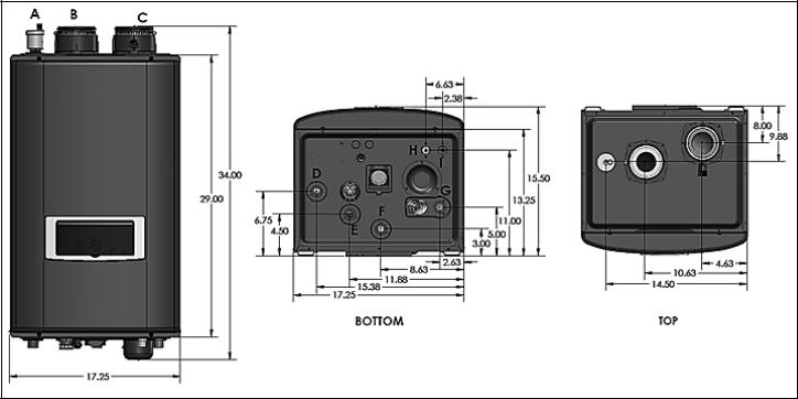
W 17.25” – H 34” – D 15.5” |
||
|
|
Minimum Flow Rate |
|
|
0.5 GPM |
|||
|
Internal Storage Tank Water Capacity (DHW) |
|
1 Gallon |
|||||
|
Boiler Heat Exchanger Capacity |
|
4 Gallons |
|||||
|
|
Total Water Capacity |
|
|
5 Gallons |
|||
|
Main Controller / Control Panel |
|
NGTX-900C / P-920C_CB-HTP |
|||||
|
|
|
CH Pressure |
|
|
Min 15 PSI - Max 30 PSI |
||
|
|
|
DHW Pressure |
|
|
Max 150 PSI |
||
|
Connection |
|
DHW Inlet / Hot Water Outlet |
|
¾” NPT |
|||
|
|
|
CH Supply / Return |
|
1” NPT |
|||
|
Sizes |
|
|
|
||||
|
|
|
|
Gas Inlet |
|
½” NPT (1/2” X ¾” Bell Coupling Provided to Upsize Gas Line) |
||
|
|
|
|
|
|
|||
|
|
|
|
|
Cabinet |
|
Cold Rolled Carbon Steel |
|
|
Materials |
|
|
|
Heat Exchanger |
|
Primary Heat Exchanger: Stainless Steel |
|
|
|
|
|
|
|
Storage Tank: Stainless Steel |
||
|
|
|
|
|
|
|
|
|
|
|
|
Safety Devices |
|
|
Flame Rod, Overheat Cut Off Device, Gas Valve Operation Detector, Exhaust |
||
|
|
|
|
|
Temperature High Limit Sensor, Water Temperature High Limit Sensor |
|||
|
|
|
|
|
|
|
|
|
|
Table 3 – Technical Specifications |
|
|
|
||||
WHL-012 REV. 12.17.14
12
Figure 1 –Specifications and Dimensions
|
DESCRIPTION |
DIAMETER (ALL NPTM) |
A |
Automatic Air Vent |
- |
B |
Intake Pipe Connection |
3” |
C |
Exhaust Vent Connection |
3” |
D |
CH Supply Adapter |
1” NPT |
E |
CH Return Adapter |
1” NPT |
F |
DHW Outlet Adapter |
¾” NPT |
G |
DHW Inlet Adapter |
¾” NPT |
H |
Gas Connection Adapter |
½” NPT (1/2” X ¾” Bell Coupling Provided to Upsize Gas Line) |
I |
Condensate Adapter |
- |
Table 4 – Adapter Specifications
WHL-012 REV. 12.17.14

13
Figure 2 – Components
NUMBER |
COMPONENT DESCRIPTION |
NUMBER |
COMPONENT DESCRIPTION |
1 |
Air Vent |
15 |
Condensate Adapter |
2 |
Air Intake Adapter |
16 |
Condensate Trap |
3 |
Air / Gas Mixing Pipe |
17 |
Condensate Air Pressure Switch |
4 |
Gas Valve |
18 |
Mixing Valve |
5 |
Internal Storage Tank |
19 |
Terminal Block |
6 |
Main PCB |
20 |
Control Panel |
7 |
Manual ON/OFF Power Switch |
21 |
Heat Exchanger |
8 |
Internal Recirculation Pump (DHW) / CH Internal Primary Pump |
22 |
Ignition Transformer |
9 |
CH Supply Adapter |
23 |
Flame Detecting Sensor |
10 |
CH Return Adapter |
24 |
BLDC Fan |
11 |
CH Pressure Gauge |
25 |
Air Pressure Switch |
12 |
DHW Outlet Adapter |
26 |
Exhaust Vent Pipe |
13 |
Gas Inlet Adapter |
27 |
Exhaust Vent Adapter |
14 |
DHW Inlet Adapter With Filter and Flow Restrictor |
28 |
CH Return Filter |
Table 5 – Component List
PART 4 – PREPARE APPLIANCE LOCATION
A. UNCRATING THE APPLIANCE
UNCRATING APPLIANCE – Any claims for damage or shortage in shipment must be filed immediately against the transportation company by the consignee.
WHL-012 REV. 12.17.14
14
Cold weather handling – If appliance has been stored in a very cold location (below 0oF) before installation, handle with care until the plastic components come to room temperature.
Remove all sides of the shipping crate to allow the appliance to be lifted into its installation location.
Carefully consider installation when determining appliance location. Please read the entire manual before attempting installation. Failure to properly take factors such as appliance venting, piping, condensate removal, and wiring into account before installation could result in wasted time, money, and possible property damage and personal injury.
B. BEFORE LOCATING THE APPLIANCE
Incorrect ambient conditions can lead to damage to the heating system and put safe operation at risk. Ensure that the appliance installation location adheres to the information included in this manual. Failure to do so could result in property damage, serious personal injury, or death.
Failure of appliance or components due to incorrect operating conditions IS NOT covered by product warranty.
1.Installation Area (Mechanical Room) Operating Conditions
Ensure ambient temperatures are higher than 32oF/0oC and lower than 104oF/40oC.
Prevent the air from becoming contaminated by the products, places, and conditions listed in this manual.
Avoid continuously high levels of humidity
Never close existing ventilation openings
The service life of the appliance’s exposed metallic surfaces, such as the casing, as well as internal surfaces, such as the heat exchanger, are directly influenced by proximity to damp and salty marine environments. In such areas, higher concentration levels of chlorides from sea spray coupled with relative humidity can lead to degradation of the heat exchanger and other appliance components. In these environments, appliances must not be installed using direct vent systems which draw outdoor air for combustion. Such appliances must be installed using room air for combustion. Indoor air will have a much lower relative humidity and, hence, potential corrosion will be minimized.
This appliance is certified for indoor installations only. Do not install the appliance outdoors. Failure to install this appliance indoors could result in substantial property damage, severe personal injury, or death.
2.Check for nearby connections to:
System water piping
Venting connections
Gas supply piping
Electrical power
Condensate drain
Locate the appliance where any leakage from the relief valve, related piping, tank, or connections will not result in damage to surrounding areas or lower floors of the building. The appliance should be located near a floor drain, or installed in an adequately drained drain pan. Westinghouse WILL NOT be held liable for leakage damages.
To conserve water and energy, insulate all water piping, especially the hot and recirculation water lines.
3. Check area around appliance. Remove any combustible materials, gasoline, and other flammable liquids.
Failure to keep appliance area clear and free of combustible materials, liquids, and vapors can result in substantial property damage, severe personal injury, or death.
WHL-012 REV. 12.17.14
15
4.Gas control system components must be protected from dripping water during operation and service.
5.If the appliance is to replace an existing appliance, check for and correct any existing system problems, such as:
System leaks
Location that could cause the system and appliance to freeze and leak.
Incorrectly-sized expansion tank
Do not connect the appliance to any heating systems or components that have been previously used for non-potable applications.
Do not introduce toxic chemicals, such as antifreeze or appliance treatments, into the appliance or any piping meant for potable water purposes.
Ensure that all piping and components connected to the appliance are suitable for potable water applications.
Do not use this appliance only for space heating applications.
Circulators suitable for DHW applications must be used.
Failure to follow these instructions could result in property damage, personal injury, or death.
6. Clean and flush system when reinstalling an appliance.
NOTE: When installing in a zero clearance location, it may not be possible to read or view some product labeling. It is recommended to make note of the appliance model and serial number.
C. LEVELING
In order for the condensate to properly flow out of the collection system, the appliance must be installed level. Failure to ensure the appliance is installed level will result in improper appliance operation.
D. CLEARANCES FOR SERVICE ACCESS
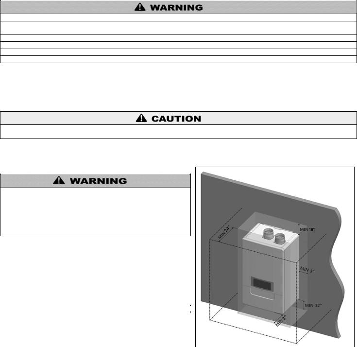
See Figure 3 and Table 6 for recommended service clearances. If these minimum clearances are not provided, it may not be possible to service the appliance without removing it from the space.
Space must be provided with combustion/ventilation air openings correctly sized for all other appliances located in the same space as the appliance. The appliance cover must be securely fastened to prevent it from drawing air from the appliance room. This is particularly important if the appliance is in a room with other appliances. Failure to comply with the above could result in substantial property damage, severe personal injury, or death.
|
MINIMUM CLEARANCES |
|
|
|
|
|||
|
Installation Clearances |
|
|
Recommended Service and Proper |
|
|
|
|
|
from Non-Combustibles / |
|
|
|
|
|
|
|
|
|
|
Operation Clearances |
|
|
|
|
|
|
Combustibles |
|
|
|
|
|
|
|
|
|
|
|
|
|
|
|
|
|
Top |
|
|
18 in. (45.7 cm) |
|
|
|
|
|
Back |
|
|
0 in. (0 cm) |
|
|
|
|
|
Bottom |
|
|
12 in. (30.45 cm) |
|
|
|
|
|
Front |
|
|
24 in. (60.9 cm) |
|
|
|
|
|
Right Side |
|
|
3 in. (7.6 cm) |
|
|
|
|
|
Left Side |
|
|
|
|
|
||
|
|
|
|
|
|
|
|
|
|
Table 6 – Minimum Installation and Service Clearances |
|||||||
|
NOTE: For closet installations, a combustible door or removable panel |
|||||||
|
is acceptable front clearance. A 3” minimum clearance must be |
|||||||
|
provided from the appliance front cover to the removable panel or |
|||||||
|
combustible door. |
|
|
|
|
|
|
|
|
|
|
|
|
Figure 3 – Minimum Service Clearances |
|
||
|
|
|
|
|
|
|
|
|
|
|
|
|
|
|
|
|
|
MINIMUM CLEARANCES FROM COMBUSTIBLE MATERIALS
Hot water pipes – at least 1” from combustible materials.
Exhaust vent pipe – at least 1” from combustible materials.
WHL-012 REV. 12.17.14

16
Always take future maintenance into consideration when locating the appliance. If the appliance is located in an installation location with limited clearances, it may be necessary to remove the appliance from the space to perform maintenance. Failure to consider maintenance when determining installation location could result in property damage.
E. RESIDENTIAL GARAGE, CLOSET, AND ALCOVE INSTALLATIONS
Check with your local Authority Having Jurisdiction for requirements when installing appliance in a garage, closet, or alcove. Please read the entire manual before attempting installation. Failure to properly take factors such as appliance venting, piping, condensate removal, and wiring into account before installation could result in wasted time, money, and possible property damage and personal injury.
PRECAUTIONS
If the appliance is located in a residential garage, it should be installed per the latest edition of the National Fuel Gas Code, ANSI Z223.1, and CGA-B149 Installation Code in Canada.
Mount the bottom of the appliance a minimum of 18” above the floor of the garage, to ensure the burner and ignition devices are well off the floor.
Locate or protect the appliance so it cannot be damaged by a moving vehicle.
For closet or alcove installations, a two pipe venting system must be used. Failure to follow this warning could result in substantial property damage, severe personal injury, or death.
The space must be provided with correctly sized combustion/ventilation air openings for all other appliances located in the space with the appliance. Do not install the appliance in an attic. Failure to comply with these warnings could result in substantial property damage, severe personal injury, or death.
F. EXHAUST VENT AND INTAKE PIPE
Vents must be properly supported. The appliance exhaust and intake connections are not designed to carry heavy weight. Vent support brackets must be within 1’ of the appliance and the balance at 4’ intervals. Venting must be readily accessible for visual inspection for the first 3’ from the appliance.
The appliance is rated ANSI Z21.13 Category IV (pressurized vent, likely to form condensate in the vent), and requires a special vent system designed for pressurized venting.
You must also install air intake piping from outdoors to the appliance flue adaptor. The resultant installation is categorized as direct vent (sealed combustion).
NOTE: To prevent combustion air contamination, see Table 7 in this section when considering exhaust vent and intake pipe termination.
Exhaust vent and intake pipe may be vented vertically through the roof or out a side wall. Venting methods are detailed in the Venting Section. Do not attempt installation using any other means. Be sure to locate the appliance so exhaust vent and intake piping can be routed through the building and properly terminated. Exhaust vent and intake piping lengths, routing, and termination method must comply with methods and limits given in the venting section.
G. PREVENT COMBUSTION AIR CONTAMINATION
Install intake piping for the appliance as described in the Venting section. Do not terminate exhaust in locations that can allow contamination of intake air.
Ensure that the intake air will not contain any of the contaminants below. For example, do not pipe intake near a swimming pool. Avoid areas subject to exhaust fumes from laundry facilities. These areas always contain contaminants. Contaminated air will damage the appliance, resulting in possible substantial property damage, severe personal injury, or death.
WHL-012 REV. 12.17.14
17
PRODUCTS TO AVOID |
AREAS LIKELY TO HAVE CONTAMINANTS |
Spray cans containing fluorocarbons |
Dry cleaning/laundry areas and establishments |
Permanent wave solutions |
Swimming pools |
Chlorinated waxes/cleaners |
Metal fabrication plants |
Chlorine-based swimming pool chemicals |
Beauty shops |
Calcium chloride used for thawing |
Refrigeration repair shops |
Sodium chloride used for water softening |
Photo processing plants |
Refrigerant leaks |
Auto body shops |
Paint or varnish removers |
Plastic manufacturing plants |
Hydrochloric or Muriatic acid |
Furniture refinishing areas and establishments |
Cements and glues |
New building construction |
Antistatic fabric softeners used in clothes dryers |
Remodeling areas |
Chlorine-type bleaches, laundry detergents, and cleaning solvents |
Garages and workshops |
Adhesives used to fasten building products |
|
Table 7 |
|
NOTE: DAMAGE TO THE APPLIANCE CAUSED BY EXPOSURE TO CORROSIVE VAPORS IS NOT COVERED BY WARRANTY.
(Refer to the limited warranty for complete terms and conditions).
H. REMOVING A APPLIANCE FROM A COMMON VENT SYSTEM
Do not install the appliance into a common vent with any other appliance. This will cause flue gas spillage or appliance malfunction, resulting in possible substantial property damage, severe personal injury, or death.
Failure to follow all instructions can result in flue gas spillage and carbon monoxide emissions, causing severe personal injury or death.
When removing an existing appliance, the following steps must be followed.
1.Seal any unused openings in the common venting system.
2.Visually inspect the venting system for proper size and horizontal pitch to determine if there is blockage, leakage, corrosion or other deficiencies that could cause an unsafe condition.
3.If practical, close all building doors, windows and all doors between the common venting system and other spaces in the building. Turn on clothes dryers and any appliances not connected to the common venting system. Turn on any exhaust fans, such as range hoods and bathroom exhausts, at maximum speed. Do not operate a summer exhaust fan. Close all fireplace dampers.
4.Place in operation the appliance being inspected. Follow the lighting
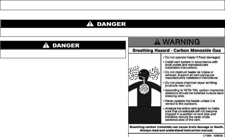
instructions. Adjust the thermostat so the appliance will operate |
|
|
Figure 4 - CO Warning Label |
||
continuously. |
||
|
||
|
|
5.Test for spillage at the draft hood relief opening after 5 minutes of main burner operation. Use the flame of a match or candle or smoke from a cigarette.
6.After it has been determined that each appliance remaining connected to common venting system properly vents when tested as outlined, return doors, windows, exhaust fans, fireplace dampers and any other gas burning appliance to their previous condition of use.
7.Any improper operation of the common venting system should be corrected so the installation conforms to the National Fuel Gas Code, ANSI Z223.1. When resizing any portion of the common venting system, the common venting system should be resized to approach the minimum size as determined using the appropriate tables in Appendix G in the National Fuel Gas Code, ANSI Z 223.1.
WHL-012 REV. 12.17.14

18
I. WALL-MOUNTING THE APPLIANCE
The appliance must be installed on a wall that can bear its weight (more than 110 lbs. when fully plumbed and full of water). Installing the appliance on a wall which cannot support its weight could result in property damage, personal injury, or death.
The appliance may be installed on any suitable internal wall (suitable sound-proofing may be required when installing onto a stud partition wall).
This appliance is too heavy for one person to lift. It is highly recommended to install the appliance with two people. Use caution as to not drop the appliance, which could damage the appliance and cause property damage and/or severe personal injury. Verify that the appliance is properly and securely mounted before leaving unsupervised. Failure to comply with the above and properly mount the appliance could result in substantial property damage, severe personal injury, or death.
This wall mounting system is not seismic rated and should not be applied as such. Failure to comply with the above and properly mount the appliance could result in substantial property damage, severe personal injury, or death.
POSITIONING THE APPLIANCE ON THE WALL
1.Attach the wall bracket on the location where you want to install the appliance. Ensure it is level and on stud (16” centers) before proceeding.
2.Mark the four drill holes with a pencil or marker. Remove the wall bracket.
3.Drill four (4) holes using a 5/32 drill bit at the marked hole locations.
4.Mount the wall bracket to the wall with the four (4) included anchor bolts. Ensure the mounted bracket is level. See Figure 5A.
5.Align the heater bracket grooves on the back of the appliance with the tongues on the wall bracket and hang the appliance on the bracket. See Figure 5B.
Figure 5 – Wall Mounting the Appliance
J. FLOW RESTRICTOR
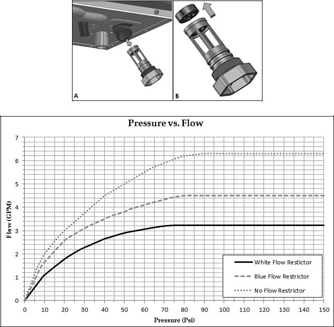
A flow restrictor is installed on this appliance at the DHW inlet adapter to avoid excessive flow at the faucets. This white flow restrictor limits flow to 3.2 GPM. An additional blue flow restrictor that limits flow to 4.5 GPM has been provided with the appliance.
If it is necessary to further increase flow to the system, replace the factory installed white flow restrictor with the blue included with the appliance by following the instructions below.
If the appliance is already fully installed, turn the gas, power, and water off to the appliance and drain all water from the appliance BEFORE proceeding. Failure to comply could result in substantial property damage, severe personal injury, or death.
1.Locate the DHW inlet adapter on the bottom of the appliance.
2.Pull the two pins to release the DHW inlet filter. See Figure 6-A. The flow restrictor is attached to the top of the filter assembly.
3.Remove the installed white flow restrictor and replace it with the blue flow restrictor included with the appliance. See Figure 6-B.
WHL-012 REV. 12.17.14
19
4.Reinstall the DHW inlet filter.
5.Reinstall the two pins.
Figure 6 – A – Removing the DHW Inlet Filter, B – Removing the Flow Restrictor
Figure 7 – Water Pressure vs. Flow Through the Restrictors
WHL-012 REV. 12.17.14
20
PART 5 – VENTING
Vent this appliance in accordance with these instructions. Failure to do so will result in property damage, severe personal injury, or death.
DO NOT mix vent systems or materials unless specifically told to do so in this manual.
DO NOT thermally insulate the exhaust vent or intake pipes.
DO NOT use an electric damper, vent damper, or draft hood with this appliance.
DO NOT locate the exhaust vent or intake pipe terminations where exposed to prevailing winds.
Moisture will be produced by the exhaust vent. Take precautions when determining exhaust vent termination. Moisture may fall from the vent termination to the ground and turn to ice in freezing conditions. Moisture or ice can produce a hazardous condition.
Exhaust condensate is acidic, and could deteriorate the surface below the exhaust vent termination. Ensure this surface is in good repair (sealed, painted, etc.) to prevent deterioration.
Pitch the exhaust vent pipe ¼” back to the appliance. This ensures that condensate in the exhaust vent returns to the appliance and drains properly.
For closet and alcove installations: CPVC, polypropylene, or stainless steel venting material MUST BE USED. Failure to follow this statement could result in product damage, severe personal injury, or death.
Failure to follow these instructions could result in property damage, severe personal injury, or death.
A. INTAKE PIPE AND EXHAUST VENT GUIDELINES
1.Vent system must be installed in accordance with local codes, or, in absence of local codes, the National Fuel Gas Code, ANSI Z223.1 / NFPA 54 and/or CSA B149.1, Natural Gas and Propane Installation Code.
2.For installation in Canada, installer supplied plastic vent piping must comply with CAN/CGA B149.1 and be certified to the Standard for Type BH Gas Venting Systems, ULC-S636. Components of this listed system must not be interchanged with other vent systems or unlisted pipes or fittings. All plastic components and specified primers and glues must be from a single system manufacturer and must not be intermixed with another system manufacturer’s products. Clean and dry all applicable surfaces before applying cement.
3.This appliance is designed to be installed as a direct vent (sealed combustion) type. Combustion air must be supplied directly from the outdoors to the burner, and the flue (exhaust) gases should be vented directly to the outdoors through the wall or roof.
4.This appliance uses 2” or 3” diameter pipe for exhaust vent and intake pipe. It is important to ensure an airtight seal from the appliance collar to the vent terminations. See Table 9 for a list of Approved Vent Materials.
5.Do not install venting system components on the exterior of the building except as specifically required by these instructions.
Vent terminals must be at least 1 foot from any door, window, or gravity inlet into the building.
Maintain the correct clearance and orientation between the exhaust vent and intake pipe terminals.
The exhaust vent and air intake terminals must be at the same height and their center lines must be spaced apart 1 foot minimum.
The bottom of the exhaust vent and intake pipe terminals must be at least 1 foot above the normal snow accumulation level. In no case should these terminals be installed less than 1 foot above normal snow accumulation level.
Do not install the exhaust vent terminals directly above windows or doors.
Intake pipe terminal must not terminate in areas that might contain combustion air contaminates, such as near swimming pools.
For sidewall venting, the minimum horizontal distance between adjacent exhaust vent terminations is 1 foot. It is recommended this distance be greater than 1 foot to better avoid frost damage to building surfaces.
For roof venting, minimum horizontal distance between any adjacent exhaust vent termination is 1 foot.
WHL-012 REV. 12.17.14
21
Figure 8 – Vent Termination Detail
|
|
|
|
DESCRIPTION |
|
US |
|
|
CANADA |
|
A |
|
|
Clearance above grade, veranda, porch, deck, or balcony |
|
1 foot |
|
1 foot |
|
|
B |
|
|
Clearance to window or door that may be opened |
|
1 foot |
|
3 feet |
|
|
C |
|
|
Clearance to permanently closed window |
* |
|
* |
||
|
|
|
|
Vertical clearance to ventilated soffit located above the |
|
|
|
|
|
|
D |
|
terminal within a horizontal distance of 2 feet from the center |
* |
|
* |
|||
|
|
|
|
line of the terminal |
|
|
|
|
|
|
E |
|
|
Clearance to unventilated soffit |
* |
|
* |
||
|
F |
|
|
Clearance to outside corner |
* |
|
* |
||
|
G |
|
|
Clearance to inside corner |
* |
|
* |
||
|
|
|
|
Clearance to each side of center line extended above meter |
|
|
|
|
3 feet with a height 15 feet |
|
H |
|
|
* |
|
|
above meter / regulator |
||
|
|
|
/ regulator assembly |
|
|
||||
|
|
|
|
|
|
|
|
assembly |
|
|
|
|
|
|
|
|
|
|
|
|
I |
|
|
Clearance to service regulator vent outlet |
* |
|
|
3 feet |
|
|
J |
|
|
Clearance to non-mechanical air supply inlet to building or |
|
1 foot |
|
3 feet |
|
|
|
|
the combustion air inlet to any other appliance |
|
|
||||
|
|
|
|
|
|
|
|
|
|
|
K |
|
|
Clearance to a mechanical air supply inlet |
|
3 feet above if within 10 feet |
|
6 feet |
|
|
|
|
|
horizontally |
|
||||
|
|
|
|
|
|
|
|
||
|
L |
|
|
Clearance above paved sidewalk or driveway located |
* |
|
|
7 feet |
|
|
M |
|
|
Clearance under veranda, porch, deck, or balcony |
* |
|
|
1 foot |
|
|
Table 8 – Vent Termination Clearances |
|
|
|
|
|
|||
*NOTE: For clearances not specified in ANSI Z223.1/NFPA 54 or CAN/CSA-B 149.1, please use clearances in accordance with local installation codes and the requirements of the gas supplier.
B. APPROVED VENT MATERIALS
NOTICE
Consult Table 9 or the most recent edition of ANSI Z223.1/NFPA 54 or CAN/CGA B149.1 as well as all applicable local codes and regulations when selecting vent pipe materials.
WHL-012 REV. 12.17.14
|
|
|
|
|
|
|
|
|
22 |
||
|
|
|
|
|
|
|
|
|
|
|
|
|
|
|
|
APPROVED EXHAUST VENT AND INTAKE PIPE MATERIAL |
|
||||||
|
Item |
|
|
Material |
|
|
Standards for Installation in: |
|
|||
|
|
|
|
|
United States |
|
|
Canada |
|
||
|
|
|
|
|
|
|
|
|
|
||
|
|
|
|
CPVC schedule 40 |
|
ASTM-D2846 |
|
PP, CPVC, and PVC venting must be |
|||
|
|
|
|
PVC schedule 40 |
|
ANSI/ASTM D1785 |
|
ULC-S636 Certified. IPEX is an approved |
|||
|
Exhaust vent or Intake |
|
|
|
|
manufacturer in Canada, supplying vent |
|||||
|
|
|
|
|
|
|
|
|
|||
|
|
|
Polypropylene |
|
ULCS636 |
|
|||||
|
pipe and fittings |
|
|
|
|
material listed to ULC-S636. |
|||||
|
|
|
|
|
|
|
|
|
|||
|
|
|
|
Stainless Steel AL29-4C |
|
Certified for Category IV and |
|
Certified for Category IV and direct vent |
|||
|
|
|
|
|
direct vent appliance venting |
|
appliance venting |
||||
|
|
|
|
|
|
|
|
||||
|
Pipe cement/primer |
|
|
PVC |
|
ANSI/ASTM D2564 |
|
IPEX System 636 Cements & Primers |
|||
|
|
|
CPVC |
|
ANSI/ASTM F493 |
|
|||||
|
|
|
|
|
|
|
|
||||
|
|
|
|
|
|
|
|
|
|
|
|
The exhaust and intake components installed with this appliance must be used for near appliance piping BEFORE transitioning to the approved materials listed above. DO NOT REMOVE these installed components. Doing so WILL VOID warranty.
PVC/CPVC pipe and fittings of the same diameter are considered interchangeable.
DO NOT use Foam Core Pipe (CPVC cellular core, Radel, etc.) in any portion of the exhaust piping from this appliance.DO NOT connect PVC/CPVC to PP without an approved vent connector.
When installing AL29-4C vent piping, install a PVC-to-stainless adapter at the appliance vent connection, and at the termination when using an Westinghouse PVC termination kit. DO NOT mix AL-29-4C piping from different manufacturers unless using adapters specifically designed for the purpose by the manufacturer.
DO NOT insulate non-metallic exhaust vent pipe or fittings.DO NOT obstruct the flow of combustion or ventilation air.
When using Pipe Cement/Primer, follow the instructions included with the Cement/Primer closely. Clean and dry all applicable surfaces before applying.
Failure to follow these directions will result in substantial property damage, severe personal injury, or death.
Table 9 – Approved Venting Materials
Vent adaptors are not designed as load-bearing devices, and must not be used to support exhaust vent piping. All vent pipes must be properly connected, supported, and the exhaust must be pitched a minimum of ¼” per foot back to the appliance to allow drainage of condensate. Failure to properly support vent piping and follow the information in this statement could result in product damage, severe personal injury, or death.
For closet and alcove installations: CPVC, polypropylene, or stainless steel venting material MUST BE USED. Failure to follow this statement could result in product damage, severe personal injury, or death.
High heat sources (sources generating heat 100oF / 37oC or greater, such as stove pipes, space heaters, etc.) may damage plastic components of the appliance as well as plastic vent pipe materials. Such damages ARE NOT covered by warranty. It is recommended to keep a minimum clearance of 8” from high heat sources. Observe heat source manufacturer instructions, as well as local, state, provincial, and national codes, laws, regulations and ordinances when installing this appliance and related components near high heat sources.
C. ALLOWED COMBINED VENT LENGTHS
2” COMBINED VENT LENGTH |
3” COMBINED VENT LENGTH |
MAXIMUM |
MAXIMUM |
50’ (15M) |
100’ (30M) |
Table 10 – Approved Vent Lengths
NOTE: When using more than 1 elbow, reduce maximum allowable length:
5 feet (1.5M) for each additional 3” 90o elbow
2.5 feet (.75M) for each additional 3” 45o elbow
8 feet (2.4M) for each additional 2” 90o elbow
4 feet (1.2M) for each additional 2” 45o elbow
WHL-012 REV. 12.17.14
23
Vent adaptors are not designed as load-bearing devices, and must not be used to support exhaust vent piping. All vent pipes must be properly connected, supported, and the exhaust must be pitched a minimum of ¼” per foot back to the appliance to allow drainage of condensate. Failure to properly support vent piping and follow the information in this statement could result in product damage, severe personal injury, or death.
D. TIGHTENING APPLIANCE COLLAR TO EXHAUST VENT AND INTAKE PIPE
NOTE: The included 6” length of 3” CPVC pipe MUST BE INSTALLED in the exhaust vent connection BEFORE venting the appliance.
Failure to properly install the included 6” length of 3” CPVC pipe BEFORE venting the appliance could result in product damage, severe personal injury, or death.
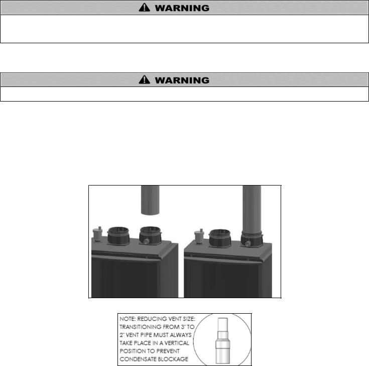
This appliance uses 2” or 3” diameter pipe for exhaust vent and intake pipe. In order to use 2” pipe, it is required to reduce pipe size in a vertical length of pipe with a reducing coupling (not included). Follow the steps below to install 2” or 3” pipe into the appliance collar. See Figure 9 for additional details.
1.Clean and dry the appliance connection. DO NOT use primer or cement on the appliance connection.
2.Push the included 6” length of CPVC pipe into the connection until it touches the bottom of the fitting.
3.Tighten the clamps using a screwdriver.
4.Ensure the pipe is secure before continuing installation.
5.For 2” installations, install a reducing coupling in a vertical section of pipe. See Figure 10.
Figure 9 – Installing the 6” Length of CPVC into the Exhaust Vent Connection
Figure 10 – Transitioning from 3” to 2” Vent Pipe
WHL-012 REV. 12.17.14
 Loading...