


Westinghouse WBCNG399WPU, WBRNG055WPU, WBRNG080WPU, WBRNG110WPU, WBRNG155WPU Installation Manual
...Gas Fired
Boiler
Residential and Commercial Models
INSTALLATION
START-UP
MAINTENANCE
PARTS
WBR Models* 055 / 080 / 110 / 155 / 199 / 285 / 399
Model Names with “LP” denote propane gas, “N” denote natural gas, and “PU” denote included pump
Heat Exchanger Bears the ASME “H” Stamp
This manual must only be used by a qualified heating installer/service technician. Read all instructions in this manual before installing. Perform steps in the order given. Failure to comply could result in substantial property damage, severe personal injury, or death.
NOTICE: Westinghouse reserves the right to make product changes or updates without notice and will not be held liable for typographical errors in literature.
NOTE TO CONSUMER: PLEASE KEEP ALL INSTRUCTIONS FOR FUTURE REFERENCE.
WHL-016 REV. 3.4.15

2
IF THE INFORMATION IN THIS MANUAL IS NOT FOLLOWED EXACTLY, A FIRE OR EXPLOSION MAY RESULT, CAUSING PROPERTY DAMAGE, PERSONAL INJURY, OR LOSS OF LIFE. DO NOT STORE GASOLINE OR OTHER FLAMMABLE VAPORS AND LIQUIDS IN THE VICINITY OF THIS OR ANY OTHER BOILER.
WHAT TO DO IF YOU SMELL GAS
Do not try to light any boiler.
Do not touch any electrical switch.
Do not use any phone in your building.
Immediately call your gas supplier from a neighbor’s phone. Follow the gas supplier’s instructions.
If you cannot reach your gas supplier, call the fire department. Installation and service must be provided by a qualified installer, service agency, or the gas supplier.
WHL-016 REV. 3.4.15
3
The following defined terms are used throughout this manual to bring attention to the presence of hazards of various risk levels, or to important product information.
DANGER indicates an imminently hazardous situation which, if not avoided, will result in death or serious injury.
WARNING indicates a potentially hazardous situation which, if not avoided, could result in death or serious injury.
CAUTION indicates a potentially hazardous situation which, if not avoided, may result in minor or moderate injury.
CAUTION used without the safety alert symbol indicates a potentially hazardous situation which, if not avoided, may result in property damage.
NOTICE
NOTICE is used to address practices not related to personal injury.
FOREWORD
This manual is intended to be used in conjunction with other literature provided with the boiler. This includes all related control information. It is important that this manual, all other documents included with this system, and additional publications including the National Fuel Gas Code, ANSI Z223.1-2002, be reviewed in their entirety before beginning any work.
Installation should be made in accordance with the regulations of the Authority Having Jurisdiction, local code authorities, and utility companies which pertain to this type of water heating equipment.
Authority Having Jurisdiction (AHJ) – The Authority Having Jurisdiction may be a federal, state, local government, or individual such as a fire chief, fire marshal, chief of a fire prevention bureau, labor department or health department, building official or electrical inspector, or others having statutory authority. In some circumstances, the property owner or his/her agent assumes the role, and at government installations, the commanding officer or departmental official may be the AHJ.
NOTE: Westinghouse reserves the right to modify product technical specifications and components without prior notice.
FOR THE INSTALLER
This manual must only be used by a qualified heating installer/service technician. Read all instructions in this manual before installing. Perform steps in the order given. Failure to comply could result in substantial property damage, severe personal injury, or death.
This boiler must be installed by qualified and licensed personnel. The installer should be guided by the instructions furnished with the boiler, and with local codes and utility company requirements. In the absence of local codes, preference should be given to the National Fuel Gas Code, ANSI Z223.1-2002.
INSTALLATIONS MUST COMPLY WITH:
Authority Having Jurisdiction, local, state, provincial, and national codes, laws, regulations and ordinances.
The latest version of the National Fuel Gas Code, ANSI Z223.1, from American Gas Association Laboratories, 8501 East Pleasant Valley Road, Cleveland, OH 44131.
In Canada – CGA No. B149 (latest version), from Canadian Gas Association Laboratories, 55 Scarsdale Road, Don Mills, Ontario, Canada M3B 2R3. Also, Canadian Electrical Code C 22.1, from Canadian Standards Association, 5060 Spectrum Way, Suite 100, Mississauga, Ontario, Canada L4W 5N6.
WHL-016 REV. 3.4.15
4
Code for the installation of Heat Producing Boilers (latest version), from American Insurance Association, 85 John Street, New York, NY 11038.
The latest version of the National Electrical Code, NFPA No. 70.
NOTE: The gas manifold and controls met safe lighting and other performance criteria when the boiler underwent tests specified in ANSI Z21.13 – latest edition.
The hydronic supply and return connections of these products are for installation in closed loop systems ONLY! Use of this product in any manner other than described in this manual may result in premature product failure, substantial property damage, severe personal injury, or death. Damage or failure of this product (or the system in which it is installed) due to unauthorized use IS NOT COVERED BY WARRANTY.
NOTICE
In accordance with Section 325 (f) (3) of the Energy Policy and Conservation Act, Westinghouse has provided this boiler with multiple features designed to save energy by reducing the boiler water temperature as heating load decreases.
These features include:
A modulating combustion system that adjusts firing rate based on heat demand.
Adjustment of boiler set point based on inferred heat load as determined by an outdoor sensor. The outdoor sensor is supplied by Westinghouse with this boiler.
This boiler does not include a standing pilot.
This boiler is designed and shipped to assure the highest efficiency operation possible. Such high efficiency is achieved by limiting heating circuit water temperature to 140°F when there is no anticipated heat load, based upon the outdoor sensor and the Outdoor Reset Curve (sensor response curve) in the boiler software.
This feature may be over-ridden as described below in specific installations:
The boiler control is equipped with an outdoor sensor override for use with building management systems or in cascaded systems (for systems with total input of 300,000 BTU/hr or greater).
See statement below for an important notice on the use of the override.
In accordance with Section 325 (f) (3) of the Energy Policy and Conservation Act, this boiler is equipped with a feature that saves energy by reducing the boiler water temperature as the heating load decreases. This feature is equipped with an override which is provided primarily to permit the use of an external energy management system that serves the same function. THIS OVERRIDE MUST NOT BE USED UNLESS AT LEAST ONE OF THE FOLLOWING CONDITIONS IS TRUE:
An external energy management system is installed that reduces the boiler water temperature as the heating load decreases.
This boiler is not used for space heating.
This boiler is part of a modular or multiple boiler system having a total input of 300,000 BTU/hr or greater.
This boiler is equipped with a tankless coil.
NOTICE
The CSD-1 ASME Code, Section CW-400 requires that hot water heating and supply boilers have a) a UL 353 temperature control device, b) at least one (1) temperature-actuated control to shut off the fuel supply when system water reaches a preset operating temperature, c) a high temperature limit control that prevents the water temperature from exceeding the maximum allowable temperature by causing a safety shutdown and lockout, and d) its own sensing element and operating switch.
Certain AHJs, locales, and states will require that commercial boiler installations meet the CSD-1 ASME Code, Section CW-400. To meet this code, Westinghouse has integrated a temperature control system into the 926 control provided with this heating appliance. This control system complies with the requirements of CSD-1 Section CW-400 as a temperature operation control. The control monitors the temperature difference between the inlet and the outlet sensor, which is affected by boiler water flow. If this temperature difference exceeds 55°F (typically because of low water flow or very low heat load), the control will reduce the maximum fan speed. If the temperature difference exceeds 60°F, the control will effectively sense there is little or no water flow or heat load and shut the boiler down. The controller will restart automatically once the temperature difference has dropped below 55°F and the minimum off time (anticycle time) has expired. In addition, if the control senses that the outlet water temperature has reached 210°F, the boiler is put into a hard lockout and requires manual reset to restart.
Installers should review the regulations of the AHJ, local and state code authorities, and utility companies which pertain to this type of boiler BEFORE performing installation.
WHL-016 REV. 3.4.15
|
5 |
TABLE OF CONTENTS |
|
PART 1 – GENERAL SAFETY INFORMATION.......................................................................................................................... |
8 |
A. PRECAUTIONS.......................................................................................................................................................................... |
8 |
B. IMPROPER COMBUSTION ....................................................................................................................................................... |
8 |
C. GAS............................................................................................................................................................................................ |
8 |
D. WHEN SERVICING THE BOILER.............................................................................................................................................. |
8 |
E. BOILER SYSTEM....................................................................................................................................................................... |
8 |
F. BOILER WATER CHEMISTRY................................................................................................................................................... |
9 |
G. FREEZE PROTECTION FLUIDS ............................................................................................................................................... |
9 |
PART 2 – BEFORE YOU START ................................................................................................................................................ |
9 |
A. WHAT’S IN THE BOX................................................................................................................................................................. |
9 |
B. HOW BOILER OPERATES ...................................................................................................................................................... |
10 |
C. OPTIONAL EQUIPMENT ......................................................................................................................................................... |
11 |
PART 3 – PREPARE BOILER LOCATION ............................................................................................................................... |
11 |
A. BEFORE LOCATING THE BOILER ......................................................................................................................................... |
11 |
B. LEVELING ................................................................................................................................................................................ |
12 |
C. CLEARANCES FOR SERVICE ACCESS ................................................................................................................................ |
12 |
D. RESIDENTIAL GARAGE, CLOSET, AND ALCOVE INSTALLATIONS.................................................................................... |
15 |
E. EXHAUST VENT AND INTAKE PIPE....................................................................................................................................... |
15 |
1. DIRECT VENT INSTALLATION OF EXHAUST VENT AND INTAKE PIPE....................................................................................................... |
15 |
2. INDOOR COMBUSTION AIR INSTALLATION IN CONFINED OR UNCONFINED SPACE .............................................................................. |
15 |
F. PREVENT COMBUSTION AIR CONTAMINATION.................................................................................................................. |
16 |
G. REMOVING AN BOILER FROM A COMMON VENT SYSTEM ............................................................................................... |
17 |
PART 4 – PREPARE BOILER................................................................................................................................................... |
17 |
A. REMOVE THE BOILER FROM PACKAGING .......................................................................................................................... |
17 |
B. WALL MOUNTING CONSIDERATIONS .................................................................................................................................. |
18 |
C. WALL MOUNTING INSTRUCTIONS ....................................................................................................................................... |
18 |
1. MOUNTING TO A WOOD STUDDED WALL .................................................................................................................................................... |
18 |
2. MOUNTING TO A METAL FRAME ................................................................................................................................................................... |
19 |
PART 5 – BOILER PIPING ........................................................................................................................................................ |
19 |
A. GENERAL PIPING INFORMATION ......................................................................................................................................... |
20 |
B. RELIEF VALVE ........................................................................................................................................................................ |
20 |
C. BACKFLOW PREVENTER ...................................................................................................................................................... |
21 |
D. SYSTEM WATER PIPING METHODS..................................................................................................................................... |
21 |
E. CIRCULATORS ........................................................................................................................................................................ |
21 |
F. HYDRONIC PIPING WITH CIRCULATORS, ZONE VALVES, AND MULTIPLE BOILERS...................................................... |
22 |
G. PIPING DETAILS ..................................................................................................................................................................... |
22 |
H. PIPING INSTALLATION........................................................................................................................................................... |
30 |
I. CIRCULATOR SIZING............................................................................................................................................................... |
30 |
J. CHECK/CONTROL WATER CHEMISTRY ............................................................................................................................... |
31 |
K. FILL AND PURGE HEATING SYSTEM.................................................................................................................................... |
32 |
|
WHL-016 REV. 3.4.15 |
|
6 |
L. GLYCOL ANTIFREEZE SOLUTIONS....................................................................................................................................... |
33 |
M. ZONING WITH ZONE VALVES ............................................................................................................................................... |
33 |
N. ZONING WITH CIRCULATORS............................................................................................................................................... |
33 |
O. MULTIPLE BOILERS ............................................................................................................................................................... |
33 |
PART 6 – VENTING, COMBUSTION AIR, AND CONDENSATE REMOVAL........................................................................... |
34 |
A. GENERAL ................................................................................................................................................................................ |
34 |
B. APPROVED MATERIALS FOR EXHAUST VENT AND INTAKE PIPE .................................................................................... |
35 |
C. REQUIREMENTS FOR INSTALLATION IN CANADA ............................................................................................................. |
35 |
D. EXHAUST VENT AND INTAKE PIPE LOCATION ................................................................................................................... |
36 |
E. EXHAUST VENT AND INTAKE PIPE SIZING.......................................................................................................................... |
40 |
F. LONGER VENT RUNS ............................................................................................................................................................. |
41 |
G. EXHAUST VENT AND INTAKE PIPE INSTALLATION............................................................................................................ |
41 |
H. VENTING DRAWINGS............................................................................................................................................................. |
42 |
1. DIRECT VENT INSTALLATION OF EXHAUST VENT AND INTAKE PIPE....................................................................................................... |
42 |
2. VENTING THROUGH AN EXISTING SYSTEM ................................................................................................................................................. |
45 |
3. INDOOR COMBUSTION AIR INSTALLATION IN CONFINED OR UNCONFINED SPACE .............................................................................. |
47 |
PART 7 – GAS PIPING.............................................................................................................................................................. |
49 |
A. GAS CONNECTION ................................................................................................................................................................. |
49 |
B. GAS PIPING............................................................................................................................................................................. |
49 |
C. CHECK INLET GAS PRESSURE............................................................................................................................................. |
50 |
D. BOILER GAS VALVE ............................................................................................................................................................... |
51 |
PART 8 – FIELD WIRING .......................................................................................................................................................... |
52 |
A. INSTALLATION MUST COMPLY WITH:.................................................................................................................................. |
52 |
B. FIELD WIRING TERMINATIONS ............................................................................................................................................. |
52 |
C. FIELD WIRING......................................................................................................................................................................... |
52 |
D. LINE VOLTAGE WIRING FOR STANDARD BOILER .............................................................................................................. |
53 |
E. ALARM CONNECTIONS .......................................................................................................................................................... |
53 |
F. LOW VOLTAGE CONNECTIONS FOR STANDARD BOILER ................................................................................................. |
53 |
G. THERMOSTAT ........................................................................................................................................................................ |
53 |
H. OUTDOOR SENSOR ............................................................................................................................................................... |
54 |
I. INDIRECT SENSOR .................................................................................................................................................................. |
54 |
J. OPTIONAL 0-10 VOLT BUILDING CONTROL SIGNAL ........................................................................................................... |
54 |
K. OPTIONAL UL353 LOW WATER CUT-OFF INTERFACE KIT ................................................................................................ |
55 |
L. WIRING OF CASCADE SYSTEM COMMUNICATION BUS .................................................................................................... |
55 |
M. CASCADE MASTER PUMP AND SENSOR WIRING.............................................................................................................. |
56 |
N. CASCADE FOLLOWER PUMP AND SENSOR WIRING......................................................................................................... |
56 |
PART 9 – START-UP PREPARATION...................................................................................................................................... |
59 |
A. CHECK / CONTROL WATER CHEMISTRY............................................................................................................................. |
59 |
B. CHECK FOR GAS LEAKS ....................................................................................................................................................... |
60 |
C. FREEZE PROTECTION (WHEN USED).................................................................................................................................. |
60 |
D. FILL AND TEST WATER SYSTEM .......................................................................................................................................... |
60 |
|
WHL-016 REV. 3.4.15 |
|
7 |
E. PURGE AIR FROM WATER SYSTEM..................................................................................................................................... |
61 |
F. CHECK THERMOSTAT CIRCUIT(S) ....................................................................................................................................... |
61 |
G. CONDENSATE REMOVAL ...................................................................................................................................................... |
61 |
H. FINAL CHECKS BEFORE STARTING BOILER ...................................................................................................................... |
62 |
I. CASCADE SYSTEM .................................................................................................................................................................. |
62 |
J. LOCKOUT CONDITION............................................................................................................................................................ |
63 |
PART 10 – START-UP PROCEDURE....................................................................................................................................... |
63 |
A. CONTROL OVERVIEW ............................................................................................................................................................ |
63 |
B. NAVIGATION OF THE DISPLAY ............................................................................................................................................. |
63 |
C. OPERATING INSTRUCTIONS ................................................................................................................................................ |
64 |
D. PROGRAMMING BOILER SETTINGS..................................................................................................................................... |
64 |
E. PROGRAMMING THE SYSTEM SETTING ............................................................................................................................. |
65 |
F. SYSTEM SETTING PROGRAM NAVIGATION ........................................................................................................................ |
65 |
G. RESETTING THE MAINTENANCE SCHEDULE ..................................................................................................................... |
68 |
PART 11 – START-UP PROCEDURES FOR INSTALLER....................................................................................................... |
68 |
A. BOILER CONTROL STATUS MENU ....................................................................................................................................... |
68 |
B. CASCADE MENU..................................................................................................................................................................... |
70 |
C. BOILER TEST MODE .............................................................................................................................................................. |
70 |
PART 12 – SHUTDOWN............................................................................................................................................................ |
71 |
A. SHUTDOWN PROCEDURE..................................................................................................................................................... |
71 |
B. VACATION PROCEDURE ....................................................................................................................................................... |
71 |
C. FAILURE TO OPERATE .......................................................................................................................................................... |
71 |
PART 13 – TROUBLESHOOTING ............................................................................................................................................ |
72 |
A. BOILER ERROR CODE ........................................................................................................................................................... |
72 |
B. BOILER ERROR ...................................................................................................................................................................... |
72 |
C. BOILER FAULT ........................................................................................................................................................................ |
72 |
D. USER INTERFACE DISPLAY .................................................................................................................................................. |
73 |
PART 14 – MAINTENANCE ...................................................................................................................................................... |
77 |
A. MAINTENANCE PROCEDURES ............................................................................................................................................. |
77 |
B. COMBUSTION CHAMBER COIL CLEANING INSTRUCTIONS FOR BOILER ....................................................................... |
78 |
C. CLEANING WATER SIDE OF HEAT EXCHANGER................................................................................................................ |
78 |
D. MAINTAINING THE CONDENSATE SYSTEM ........................................................................................................................ |
79 |
BOILER START-UP REPORT................................................................................................................................................... |
85 |
MAINTENANCE REPORT ......................................................................................................................................................... |
85 |
MAINTENANCE NOTES ....................................................................................................................................................................................... |
89 |
CUSTOMER INSTALLATION RECORD FORM.................................................................................................................................................... |
90 |
WHL-016 REV. 3.4.15
8
PART 1 – GENERAL SAFETY INFORMATION
A. PRECAUTIONS
This boiler is for indoor installations only. Clearance to combustible materials: 6” top, bottom, and sides, 0” back. Left side has all boiler mechanical connections. Front must have room for service, 24” recommended. (A combustible door or removable panel is acceptable front clearance.) This boiler has been approved for closet installation. Do not install this boiler directly on carpeting. For installation on combustible flooring. Category IV vent systems only.
INSTALLER – Read all instructions in this manual before installing. Perform steps in the order given.
USER – This manual is for use only by a qualified heating installer/service technician. Have this boiler serviced/inspected by a qualified service technician annually.
FAILURE TO ADHERE TO THE GUIDELINES ON THIS PAGE AND HAVE THIS BOILER SERVICED/INSPECTED ANNUALLY CAN RESULT IN SUBSTANTIAL PROPERTY DAMAGE, SEVERE PERSONAL INJURY, OR DEATH.
NOTE: When inquiring about service or troubleshooting, reference the model and serial numbers from the boiler rating label.
DO NOT USE THIS BOILER IF ANY PART HAS BEEN SUBMERGED IN WATER. Immediately call a qualified service technician. The boiler MUST BE replaced if it has been submerged. Attempting to operate a boiler that has been submerged could create numerous harmful conditions, such as a potential gas leakage causing a fire and/or explosion, or the release of mold, bacteria, or other harmful particulates into the air. Operating a previously submerged boiler could result in property damage, severe personal injury, or death.
NOTE: Boiler damage due to flood or submersion is considered an Act of God, and IS NOT covered under product warranty.
Be sure to disconnect electrical power before opening boiler cabinet or performing service. Failure to do so could result in an electrical shock that could result in property damage, serious personal injury, or death.
NOTE: If the boiler is exposed to the following, do not operate until all corrective steps have been made by a qualified serviceman:
1.FIRE
2.DAMAGE
3.WATER
Any claims for damage or shortage in shipment must be filed immediately against the transportation company by the consignee.
Due to the low water content of the boiler, improper sizing of the boiler with regard to heating system load will result in excessive cycling and accelerated component failure. Westinghouse DOES NOT warrant failures caused by improperly sized boiler applications. DO NOT oversize the boiler to the system. Modular boiler installations greatly reduce the likelihood of boiler oversizing.
B. IMPROPER COMBUSTION
Do not obstruct the flow of combustion and ventilating air. Adequate air must be provided for safe operation. Failure to keep the vent and combustion air intake clear of ice, snow, or other debris could result in property damage, serious personal injury, or death.
C. GAS
Should overheating or gas supply fail to shut off, do not turn off or disconnect electrical supply to the circulator. Instead, shut off the gas supply at a location external to the boiler.
D. WHEN SERVICING THE BOILER
To avoid electric shock, disconnect electrical supply before performing maintenance.
To avoid severe burns, allow boiler to cool.
E. BOILER SYSTEM
Thoroughly flush the system (without boiler connected) to remove sediment. The high-efficiency heat exchanger can be damaged by build-up or corrosion due to sediment. Westinghouse recommends a suction strainer in all systems.
WHL-016 REV. 3.4.15
9
Do not use petroleum-based cleaning or sealing compounds in boiler system. Gaskets and seals in the system may be damaged, possibly resulting in substantial property damage.
Do not use “homemade cures” or “boiler patent medicines”. Substantial property damage, damage to boiler, and/or serious personal injury may result.
Continual fresh make-up water will reduce boiler life. Mineral buildup in the heat exchanger reduces heat transfer, overheats the stainless steel heat exchanger, and causes failure. Addition of oxygen from make-up water can cause internal corrosion in system components. Leaks in the boiler or piping must be repaired at once.
F. BOILER WATER CHEMISTRY
Sodium less than 20mGL.
Water pH between 6 and 8
oMaintain water pH between 6 and 8. Check with litmus paper or have it chemically analyzed by water treatment company.
oIf the pH differs from above, consult local water treatment company for treatment needed.
Hardness less than 7 grains
oConsult local water treatment companies for unusually hard water areas (above 7 grains hardness).
Chlorine concentration less than 100 ppm
oUsing chlorinated fresh water should be acceptable as levels are typically less than 5 ppm.
oDo not connect the boiler to directly heat swimming pool or spa water.
oDo not fill boiler or operate with water containing chlorine in excess of 100 ppm.
NOTE: It is recommended to clean heat exchanger at least once a year to prevent lime scale buildup. To clean the heat exchanger, follow the maintenance procedure in Part 13, Section B of this manual.
ACIDITY |
6 to 8 pH |
CONDUCTIVITY |
Less than 400 uS/cm at 25oC |
CHLORIDE |
Less than 100 ppm |
IRON |
Less than 0.5 mg/L |
COPPER |
Less than 0.1 mg/L |
SODIUM |
Less than 20 mg/L |
HARDNESS |
Less than 7 Grains |
Table 1 – Water Quality Requirements |
|
G. FREEZE PROTECTION FLUIDS
NEVER use automotive or standard glycol antifreeze, or ethylene glycol made for hydronic systems, with this boiler. Use only inhibited propylene glycol solutions, which are specifically formulated for hydronic systems. Ethylene glycol is toxic and can attack gaskets and seals used in hydronic systems.
Consider boiler piping and installation when determining boiler location.
NOTE: Damages resulting from incorrect installation or from use of products not approved by Westinghouse ARE NOT covered by warranty.
PART 2 – BEFORE YOU START
A. WHAT’S IN THE BOX
Also included with the boiler:
Temperature and Pressure Gauge (Part #7500P-098)
Pressure Relief Valve (Part #7250P-080 for 055/080/110/155/199, #7350P-066 for 285/399)
Wall Mount Bracket (Part # 7600P-021 for 055/080/110, #7600P-121 for 155/199/285, #7600P-221 for 399)
Indirect Sensor (Part # 7250P-325)
Outdoor Sensor (Part # 7250P-319)
Intake PVC Tee with Screens
WHL-016 REV. 3.4.15
10
Exhaust PVC Coupling with Screens
Installation Manual
Warranty
CSD-1 Form
H-2 Data Sheet
NAT to LP Conversion Kit (Included with NAT models)
B. HOW BOILER OPERATES
Condensing technology intelligently delivers hydronic heating while maximizing efficiency. Outlined below are the features of the system and how they operate:
Stainless Steel Heat Exchanger - The highly efficient stainless steel heat exchanger is designed to extract all available heat from the supply line before it is exhausted.
Modulating Combustion System - The combustion system will modulate the output of the burner during operation to match the system demand and achieve the control set point while in operation. The set point can change by internal or external signals which enhance the overall performance of the system.
Control – The integrated control system monitors the system and regulates fan speed to control boiler output. This allows the boiler to deliver only the amount of heat energy required and nothing more.
The control can be set up to monitor outdoor temperature through an outdoor sensor to regulate boiler set point. The system can be further enhanced by installing an indirect water heater to provide domestic hot water.
The control can regulate the output of multiple boilers through its cascade system function. The cascade system is capable of connecting up to eight boilers together in such a way that they function as one boiler system. This allows for greater turn down ratios and provides systematic control of the multiple boilers in an installation to minimize downtime and maximize efficiency.
The cascade system works by establishing one boiler as the master and the other connected boilers as followers. The master boiler requires a sensor to provide feedback on set point temperature in order to adjust heating input from the connected boilers. Each cascaded boiler will have its own pump to provide maximum flow and control heat exchanger flow rate.
Text Display and Operational LED Light Indicators – The display allows the user to change system parameters and monitor system outputs.
Gas Valve – Senses suction from the blower, allowing gas to flow only if powered and combustion air is flowing.
All Metal Integrated Venturi – Controls air and gas flow into the burner.
Burner – Constructed of high grade stainless steel, the burner uses premixed air and gas fuel and provides a wide range of firing rates.
Spark Ignition – The burner is ignited by applying high voltage through the system spark electrode. This causes the spark from the electrode to ignite mixed gas off of the burner.
Supply Water Temperature Sensor – This sensor monitors boiler outlet water temperature (System Supply). The control adjusts boiler firing rate so the supply temperature will match boiler set point.
Return Water Temperature Sensor – This sensor monitors the boiler return water temperature (System Return).
Flue Sensor – Monitors flue temperature and adjusts firing rate.
Temperature and Pressure Gauge – Allows the user to monitor system temperature and pressure.
Electrical field connections with terminal strips – The electrical cover allows easy access to the line voltage and low voltage terminals strips which are clearly marked to facilitate wiring of the boiler.
Condensation Collection System – This boiler is a high efficiency boiler, and will produce condensate. The collection system has a float switch which monitors the condensation level and prevents condensation from backing up into the combustion system. Inside the collection system there is a built in trap which seals the combustion system from the connected drain. This condensate should be neutralized to avoid damage to the drainage system or piping.
Outdoor Sensor – The outdoor sensor monitors outdoor temperature and adjusts boiler set point to provide greater efficiency.
0-10 Volt Input – Allows Installer to connect a BMS (Building Management System) to control the boiler.
WHL-016 REV. 3.4.15
11
Condensate Flue Check System – The check system prevents exhaust from the heat exchanger from backing up into cabinet.
Pump Service Mode – Allows manual operation of pumps to commission system and check pump operation.
The Vision II System (Optional) – Allows the user to supply mixed temperatures in up to eight zones. The Vision II system controls the temperature to each zone by employing three way mixing valves. The Vision II also controls the output temperature of the boiler to assure accurate temperature delivery to all connected zones.
C. OPTIONAL EQUIPMENT
Below is a list of optional equipment available from Westinghouse. These additional options may be purchased through your Westinghouse distributor:
System Sensor (Part # 7250P-324)
Indirect Tank Sensor (Part # 7250P-325)
3" PVC Concentric Vent Kit (Part # KGAVT0601CVT)
3” Stainless Steel Outside Termination Vent Kit (Part # V1000)
4” Stainless Steel Outside Termination Vent Kit (Part # V2000)
6” Stainless Steel Outside Termination Vent Kit (Part # V3000)
3” Polypro Vent Kit (Part # 8400P-001)
3” Polypro Pipe (33’ length Part # 8400P-002, 49.5’ length Part # 8400P-003)
U.L. 353 Compliant Low Water Cut-Off Interface Kit with Manual Reset (Part # 7600P-104 for 055/080/110, #7600P-990 for all other models)
Manual Reset High Limit (Part # 7450P-217)
Alarm System (Part # 7350P-602) (to monitor any failure)
PC Connection Kit (Part # 7250P-320)
Condensate Neutralizer (Part # 7450P-212)
Condensate Removal Pump (Part # 554200)
Flow Switch Kit (Part # 7450P-213)
Vision II (Part # 7250P-322)
NOTE: When using an optional system sensor, pipe insulation must be wrapped around it to improve temperature measurement accuracy and increase overall system efficiency.
PART 3 – PREPARE BOILER LOCATION
Carefully consider installation when determining boiler location. Please read the entire manual before attempting installation. Failure to properly take factors such as boiler venting, piping, condensate removal, and wiring into account before installation could result in wasted time, money, and possible property damage and personal injury.
A. BEFORE LOCATING THE BOILER
Incorrect ambient conditions can lead to damage to the heating system and put safe operation at risk. Ensure that the boiler installation location adheres to the information included in this manual. Failure to do so could result in property damage, serious personal injury, or death.
Failure of boiler or components due to incorrect operating conditions IS NOT covered by product warranty.
1.Installation Area (Mechanical Room) Operating Conditions
Ensure ambient temperatures are higher than 32oF/0oC and lower than 104oF/40oC.
Prevent the air from becoming contaminated by the products, places, and conditions listed in this manual, Part 3, Section F.
Avoid continuously high levels of humidity
Never close existing ventilation openings
The service life of the boiler’s exposed metallic surfaces, such as the casing, as well as internal surfaces, such as the heat exchanger, are directly influenced by proximity to damp and salty marine environments. In such areas, higher concentration levels of chlorides from sea spray coupled with relative humidity can lead to degradation of the heat exchanger and other boiler components. In these
WHL-016 REV. 3.4.15
12
environments, boilers must not be installed using direct vent systems which draw outdoor air for combustion. Such boilers must be installed using room air for combustion. Indoor air will have a much lower relative humidity and, hence, potential corrosion will be minimized.
This boiler is certified for indoor installations only. Do not install the boiler outdoors. Failure to install this boiler indoors could result in substantial property damage, severe personal injury, or death.
2.Check for nearby connections to:
System water piping
Venting connections
Gas supply piping
Electrical power
Condensate drain
3.Check area around boiler. Remove any combustible materials, gasoline, and other flammable liquids.
Failure to keep boiler area clear and free of combustible materials, liquids, and vapors can result in substantial property damage, severe personal injury, or death.
4.Gas control system components must be protected from dripping water during operation and service.
5.If the boiler is to replace an existing boiler, check for and correct any existing system problems, such as:
System leaks
Location that could cause the system and boiler to freeze and leak.
Incorrectly-sized expansion tank
6.Clean and flush system when reinstalling a boiler.
NOTE: When installing in a zero clearance location, it may not be possible to read or view some product labeling. It is recommended to make note of the boiler model and serial number.
Gas conversion should be performed BEFORE the boiler is installed. Carefully follow the gas conversion instructions when performing the conversion. Failure to do so could result in property damage, severe personal injury, or death.
Consider boiler piping and installation when determining boiler location.
B. LEVELING
In order for the condensate to properly flow out of the collection system, the boiler must be installed level. The location must also support the boiler when it is full of water.
C. CLEARANCES FOR SERVICE ACCESS
See Figure 1 for recommended service clearances. If you do not provide the minimum clearances shown, it may not be possible to service the boiler without removing it from the space.
WHL-016 REV. 3.4.15

13
Figure 1 – Required Clearances
Space must be provided with combustion/ventilation air openings correctly sized for all other boilers located in the same space as the boiler. The boiler cover must be securely fastened to prevent it from drawing air from the mechanical room. This is particularly important if the boiler is in a room with other boilers. Failure to comply with the above warnings could result in substantial property damage, severe personal injury, or death.
Always take future maintenance into consideration when locating the boiler. If the boiler is located in an installation location with limited clearances, it may be necessary to remove the boiler from the space to perform maintenance. Failure to consider maintenance when determining installation location could result in property damage.
MINIMUM CLEARANCES FROM COMBUSTIBLE MATERIALS
Hot water pipes – at least 1” from combustible materials.
Exhaust vent pipe – at least 1” from combustible materials.
WHL-016 REV. 3.4.15
14
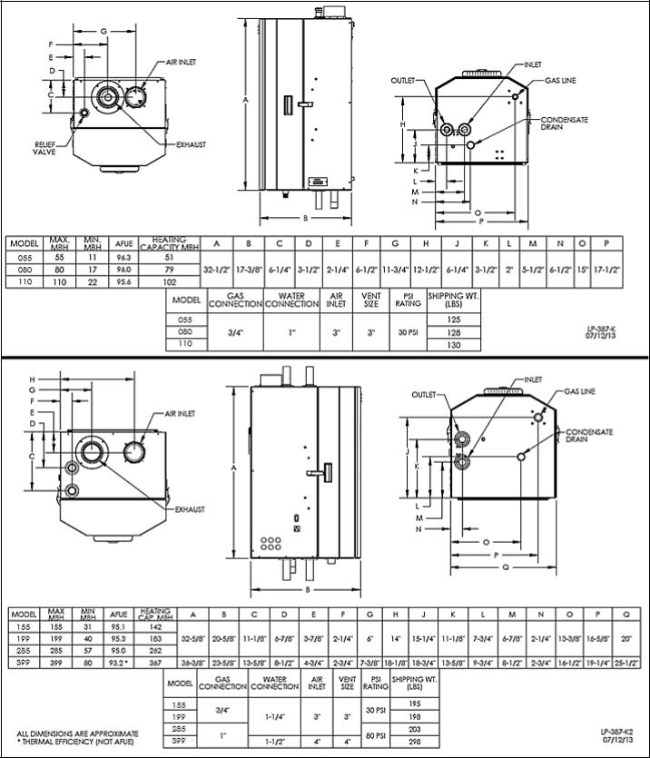
SPECIFICATIONS AND DIMENSIONS
Figure 2 – Specifications and Dimensions
WHL-016 REV. 3.4.15
15
D. RESIDENTIAL GARAGE, CLOSET, AND ALCOVE INSTALLATIONS
Check with your local Authority Having Jurisdiction for requirements when installing boiler in a garage, closet, or alcove. Please read the entire manual before attempting installation. Failure to properly take factors such as boiler venting, piping, condensate removal, and wiring into account before installation could result in wasted time, money, and possible property damage and personal injury.
PRECAUTIONS
If the boiler is located in a residential garage, it should be installed per the latest edition of the National Fuel Gas Code, ANSI Z223.1, and CGA-B149 Installation Code in Canada.
Mount the bottom of the boiler a minimum of 18” above the floor of the garage, to ensure the burner and ignition devices are well off the floor.
Locate or protect the boiler so it cannot be damaged by a moving vehicle.
For closet or alcove installations, a two pipe venting system must be used. Failure to follow this warning could result in substantial property damage, severe personal injury, or death.
The space must be provided with correctly sized combustion/ventilation air openings for all other boilers located in the space with the boiler. Do not install the boiler in an attic. Failure to comply with these warnings could result in substantial property damage, severe personal injury, or death.
NOTE: For installations using room air for combustion, refer to the boiler venting section, Part 6 in this manual.
E. EXHAUST VENT AND INTAKE PIPE
The appliance is rated ANSI Z21.13 Category IV (pressurized vent, likely to form condensate in the vent) and requires a special vent system designed for pressurized venting.
NOTE: The venting options described here (and further detailed in the Venting section of this manual) are the lone venting options approved for this appliance. Failure to vent the appliance in accordance with the provided venting instructions will void the warranty.
Failure to vent the appliance properly will result in serious personal injury or death.
Vents must be properly supported. Appliance exhaust and intake connections are not designed to carry heavy weight. Vent support brackets must be within 1’ of the appliance and the balance at 4’ intervals. Appliance must be readily accessible for visual inspection for the first 3’ from the appliance.
1. DIRECT VENT INSTALLATION OF EXHAUST VENT AND INTAKE PIPE
If installing a direct vent option, combustion air must be drawn from the outdoors directly into the appliance intake, and exhaust must terminate outside. There are three basic direct vent options detailed in this manual: 1. Side Wall Venting, 2. Roof Venting, and 3. Unbalanced Venting.
Be sure to locate the appliance such that the exhaust vent and intake piping can be routed through the building and properly terminated. Different vent terminals can be used to simplify and eliminate multiple penetrations in the building structure (see Optional Equipment in Venting Section). The exhaust vent and intake piping lengths, routing and termination methods must all comply with the methods and limits given in the Venting section of this manual.
When installing a combustion air intake from outdoors, care must be taken to utilize uncontaminated combustion air. NOTE: To prevent combustion air contamination, see Table 2.
2. INDOOR COMBUSTION AIR INSTALLATION IN CONFINED OR UNCONFINED SPACE
This appliance requires fresh, uncontaminated air for safe operation and must be installed in a mechanical room where there is adequate combustion and ventilating air. NOTE: To prevent combustion air contamination, see Table 2.
Combustion air from the indoor space can be used if the space has adequate area or when air is provided through a duct or louver to supply sufficient combustion air based on the appliance input. Never obstruct the supply of combustion air to the appliance. If the
WHL-016 REV. 3.4.15
16
appliance is installed in areas where indoor air is contaminated (see Table 2) it is imperative that the appliance be installed as direct vent so that all combustion air is taken directly from the outdoors into the appliance intake connection.
Unconfined space is space with volume greater than 50 cubic feet per 1,000 Btu/hour (4.8 cubic meters per kW) of the total input rating of all fuel-burning appliances installed in that space. Rooms connected directly to this space, through openings not furnished with doors, are considered part of the space.
Confined space is space with volume less than 50 cubic feet per 1,000 Btu/hour (4.8 cubic meters per kW) of the total input rating of all fuel-burning appliances installed in that space. Rooms connected directly to this space, through openings not furnished with doors, are considered part of the space.
When drawing combustion air from inside a conventionally constructed building to a confined space, such space should be provided with two permanent openings: one located 6” (15 cm) below the space ceiling, the other 6” (15cm) above the space floor. Each opening should have a free area of one square inch per 1,000 Btu/hr (22cm2/kW) of the total input of all appliances in the space, but not less than 100 square inches (645cm2).
If the confined space is within a building of tight construction, air for combustion must be obtained from the outdoors as outlined in the Venting Section of this manual.
When drawing combustion air from the outside into the mechanical room, care must be taken to provide adequate freeze protection.
Do not attempt to vent this appliance by any means other than those described in this manual. Doing so will void the warranty, and may result in severe personal injury or death.
Failure to provide an adequate fresh combustion air can cause poisonous flue gases to enter living space, which could result in severe personal injury or death. To prevent combustion air contamination, see Table 2.
F. PREVENT COMBUSTION AIR CONTAMINATION
Install intake piping for the boiler as described in the Venting section. Do not terminate exhaust in locations that can allow contamination of intake air.
|
PRODUCTS TO AVOID |
AREAS LIKELY TO HAVE CONTAMINANTS |
|
Spray cans containing fluorocarbons |
Dry cleaning/laundry areas and establishments |
|
Permanent wave solutions |
Swimming pools |
|
Chlorinated waxes/cleaners |
Metal fabrication plants |
|
Chlorine-based swimming pool chemicals |
Beauty shops |
|
Calcium chloride used for thawing |
Refrigeration repair shops |
|
Sodium chloride used for water softening |
Photo processing plants |
|
Refrigerant leaks |
Auto body shops |
|
Paint or varnish removers |
Plastic manufacturing plants |
|
Hydrochloric or Muriatic acid |
Furniture refinishing areas and establishments |
|
Cements and glues |
New building construction |
|
Antistatic fabric softeners used in clothes dryers |
Remodeling areas |
|
Chlorine-type bleaches, laundry detergents, and cleaning solvents |
Garages and workshops |
|
Adhesives used to fasten building products |
|
|
Table 2 |
|
|
|
|
|
|
|
You must ensure that intake air will not contain any of the contaminants listed in Table 2. For example, do not pipe intake vent near a swimming pool. Avoid areas subject to exhaust fumes from laundry facilities. These areas always contain contaminants. Contaminated air will damage the boiler, resulting in possible substantial property damage, severe personal injury, or death.
WHL-016 REV. 3.4.15
17
NOTE: DAMAGE TO THE BOILER CAUSED BY EXPOSURE TO CORROSIVE VAPORS IS NOT COVERED BY WARRANTY. (Refer to the limited warranty for complete terms and conditions).
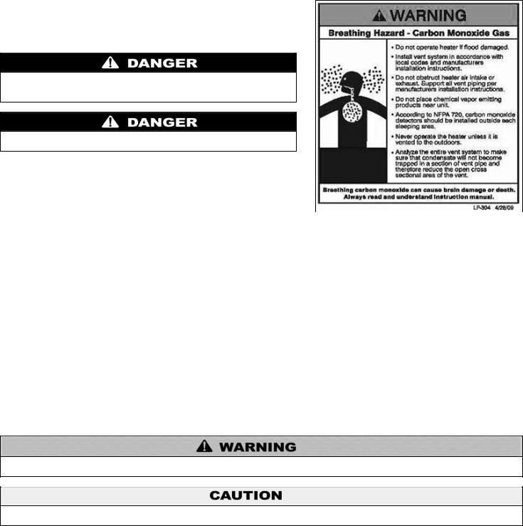
G. REMOVING AN BOILER FROM A COMMON VENT SYSTEM
Do not install the boiler into a common vent with any other boiler. This will cause flue gas spillage or boiler malfunction, resulting in possible substantial property damage, severe personal injury, or death.
Failure to follow all instructions can result in flue gas spillage and carbon monoxide emissions, causing severe personal injury or death.
When removing an existing boiler, the following steps must be followed.
1.Seal any unused openings in the common venting system.
2.Visually inspect the venting system for proper size and horizontal pitch to
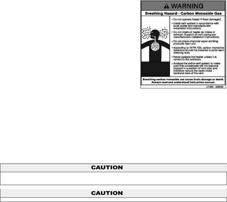
determine if there is blockage, leakage, corrosion or other deficiencies that |
Figure 3 – CO Warning Label |
|
could cause an unsafe condition. |
|
|
|
|
3.If practical, close all building doors, windows and all doors between the common venting system and other spaces in the building. Turn on clothes dryers and any boilers not connected to the common venting system. Turn on any exhaust fans, such as range hoods and bathroom exhausts, at maximum speed. Do not operate a summer exhaust fan. Close all fireplace dampers.
4.Place in operation the boiler being inspected. Follow the lighting instructions. Adjust the thermostat so the boiler will operate continuously.
5.Test for spillage at the draft hood relief opening after 5 minutes of main burner operation. Use the flame of a match or candle or smoke from a cigarette.
6.After it has been determined that each boiler remaining connected to common venting system properly vents when tested as outlined, return doors, windows, exhaust fans, fireplace dampers and any other gas burning boiler to their previous condition of use.
7.Any improper operation of the common venting system should be corrected so the installation conforms to the National Fuel Gas Code, ANSI Z223.1. When resizing any portion of the common venting system, the common venting system should be resized to approach the minimum size as determined using the appropriate tables in Appendix G in the National Fuel Gas Code, ANSI Z 223.1.
PART 4 – PREPARE BOILER
UNCRATING BOILER – Any claims for damage or shortage in shipment must be filed immediately against the transportation company by the consignee.
Cold weather handling – If boiler has been stored in a very cold location (below 0oF) before installation, handle with care until the plastic components come to room temperature.
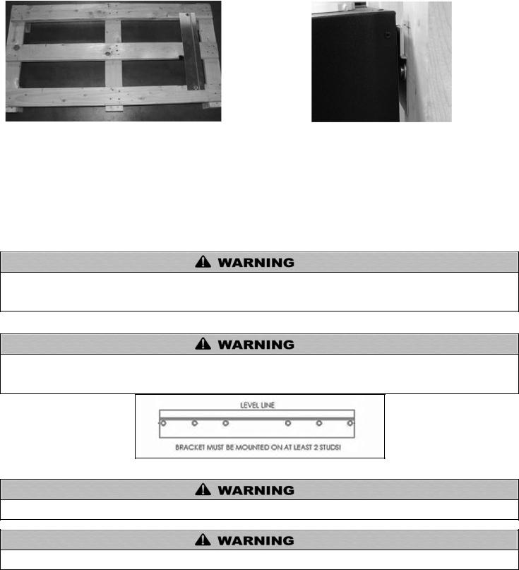
A. REMOVE THE BOILER FROM PACKAGING
Remove all sides of the shipping crate, and the wooden block that holds the boiler in place during shipping. Slide the boiler from the mounting bracket, which is affixed to the skid (Figure 4 and 5). Remove the mounting bracket from the crate (Figure 5). Take care to place the boiler in a safe location prior to installation to prevent damage to the mechanical connections.
WHL-016 REV. 3.4.15
18
Figure 4 – Pallet with Mounting Bracket Affixed |
Figure 5 –Boiler Mounted to Bracket |
B. WALL MOUNTING CONSIDERATIONS
These boilers are wall mounted. Use only the wall mounting instructions included in this manual.
Ensure the wall that the boiler is intended to be mounted on is comprised of cement, brick, block, or wooden studs spaced 16” apart from center. Ensure the wall is capable of supporting at least 250 lbs (115 kg) for 055 – 110 models, 300 lbs (136 kg) for 155 – 285 models, and 500 lbs (227 kg) for 399.
If flooding is possible, elevate the boiler to prevent floodwater from reaching the boiler.
Ensure the boiler is installed in a location that minimizes the risk of water damage due to leaking valves, pumps, unions, etc.
The mounting location must be capable of carrying the weight of the boiler and its related components. If the mounting location cannot support a minimum of 250 lbs. (115 kg), it is recommended to locate the boiler in a mounting location that can support the minimum weight. Failure to comply with the above and properly mount the boiler could result in substantial property damage, severe personal injury, or death.
C. WALL MOUNTING INSTRUCTIONS
This boiler is too heavy for one person to lift. It is highly recommended to install the boiler with two people. Use caution as to not drop the boiler, which could damage the boiler and cause property damage and/or severe personal injury. Verify that the boiler is properly and securely mounted before leaving unsupervised. Failure to comply with the above and properly mount the boiler could result in substantial property damage, severe personal injury, or death.
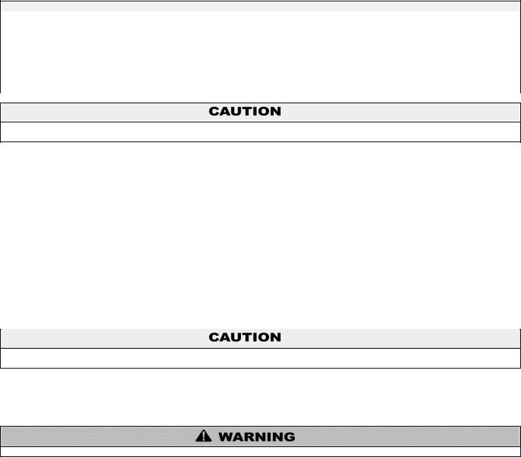
Figure 6 – Wall Mounting Bracket – NOTE: Drawing for Demonstration Purposes ONLY
This wall mounting system is not seismic rated and should not be applied as such. Failure to comply with the above and properly mount the boiler could result in substantial property damage, severe personal injury, or death.
DO NOT use the bolts included in shipping for wall mounting the boiler. Doing so may result in property damage, serious injury, or death.
1. MOUNTING TO A WOOD STUDDED WALL
a. The building frame (studs) must be 2 X 4 minimum and 16” on center (24” on the 399). If not, you must use ½” minimum plywood 24” x 48” with at least fourteen (14) #12 x 3” (3/16” x 3”) round head tapping screws to the frame of the building to provide proper support for the boiler. No alternate methods of mounting or fastening (ex. Toggle bolts, hollow wall anchors, or any other fastener) may be used.
WHL-016 REV. 3.4.15
19
b.The provided mounting bracket must be mounted directly to the center of at least 2 studs using standard steel or stainless steel ¼” x 2 ½” lag bolts for all models. Be sure the bracket is level and mark the hole location of the bracket height and horizontal stud location. Ensure the marked holes are located in the center of the building frame (studs).
c.For all models, 2 ½” is the minimum lag bolt length if the bracket is directly on stud. Increase lag bolt length for any materials covering the studs.
d.Predrill pilot holes on the marked stud locations. The pilot holes for bare studs should be 2” deep for all models. See table below for pilot hole diameter by wood type. Increase length for any material covering the stud. Ensure that the predrilled holes are straight and square to the wall. Failure to do so could lead to insufficient support or out of level boiler. See Figure 6.
NOTE: Bolt must embed into the wood structure a minimum of 2”.
d. Using the predrilled holes, mount the hanger bracket to the building frame (studs) using the appropriately sized standard steel (or stainless) lag bolt. Hang boiler on the wall mounted bracket. Be sure that the bracket is engaged before letting the boiler hang free. Slowly release the weight of the boiler while ensuring that the bracket is properly secured. Verify that the boiler is securely mounted before leaving the boiler unsupervised.
REQUIRED AMOUNT OF BOLTS FOR WALL MOUNTING THE BOILER
MODEL |
|
AMOUNT OF BOLTS |
055 –110 |
|
2 |
155 – 285 |
|
4 |
399 |
|
6 |
|
PILOT HOLE SIZE BY WOOD TYPE |
|
TYPE |
|
DRILL BIT SIZE |
SOFT |
|
3/32” |
HARD |
|
3/16” |
|
|
|
|
|
|
If the boiler is not installed vertically plumb, improper and unsatisfactory operation may occur, causing excessive condensation build-up, nuisance fault codes, and unnecessary maintenance.
2. MOUNTING TO A METAL FRAME
a.The provided mounting bracket must be mounted to the center of at least 2 studs using standard steel or stainless steel toggle bolts
3/16” diameter or larger, and at least 2” long for direct mounting on stud for 055 – 110 models, and 3/8” diameter or larger, and at least
2” long for 155 – 399 models for direct mounting on at least 18 gauge studs. Be sure the bracket is level and mark the hole location of the top bracket height and horizontal stud location. Ensure the marked holes are located in the center of the building frame (studs).
b.2” is the minimum toggle bolt length if the bracket is directly on stud. Increase length for any materials covering the studs.
c.Predrill holes on the marked stud locations. The predrilled holes should be ½” in diameter for 3/16” bolts, and ¾” in diameter for 3/8” bolts, to allow for the collapsed wings of the toggle to slide through. Ensure that the predrilled holes are straight and square to the wall. Failure to do so could lead to insufficient support of out of level boiler. See Figure 6.
d.Using the predrilled holes, mount the hanger bracket to the building frame (studs) with the toggle bolts. Ensure that the bolt toggles are through the stud and expanded catching the inside of the stud. Tighten the toggle bolt until the mounting bracket is secure. Hang boiler on the now wall mounted bracket. Be certain that the bracket is engaged before letting the boiler hang free. Slowly release the weight of the boiler while ensuring the bracket is properly secure. Verify that the boiler is securely mounted before leaving it unsupervised.
If the boiler is not installed upright and level, improper and unsatisfactory operation may occur, causing excessive condensation buildup, nuisance fault codes, and unnecessary maintenance.
PART 5 – BOILER PIPING
Failure to follow the instructions in this section WILL VOID the warranty and may result in property damage, serious injury, or death.
WHL-016 REV. 3.4.15
20
Never use dielectric unions or galvanized steel fittings when connecting to a stainless steel storage tank or boiler. Failure to follow this instruction can lead to premature failure of the boiler system. Such failures ARE NOT covered by warranty.
Plumbing of this product should only be done by a qualified, licensed plumber in accordance with all local plumbing codes. The boiler may be connected to a storage tank to supply domestic hot water. Westinghouse offers 60/80/119/175 gallon size storage tanks in either stainless steel or glass-lined construction. These storage tanks can be directly connected to the boiler supply and return connection.
The National Standard Plumbing Code, the National Plumbing Code of Canada, and the Uniform Plumbing Code limit the pressure of the heat transfer fluid to less than the minimum working pressure of the potable water system up to 30 psi maximum. The heat transfer fluid must be water or other non-toxic fluid having a toxicity of Class 1, as listed in Clinical Toxicology of Commercial Products, 5th Edition.
A. GENERAL PIPING INFORMATION
The building piping system must meet or exceed the piping requirements in this manual.
Use two wrenches when tightening water piping at the boiler. Use one wrench to prevent the boiler return or supply line from turning. Failure to prevent piping connections from turning could cause damage to boiler components.
The control module uses temperature sensors to provide both high limit protection and modulating temperature control. The control module may also provide low water protection (through the addition of an optional kit) by sensing the water level in the heat exchanger. An optional flow switch may be installed on the supply of the system to activate the boiler when there is enough flow. Some codes/jurisdictions may require additional external controls.
NOTE: The addition of a high temperature limiting device is important if the boiler is to be connected to a domestic hot water system.
B. RELIEF VALVE
To avoid water damage or scalding due to relief valve operation:
Discharge line must be connected to relief valve outlet and run to a safe place of disposal. Terminate the discharge line in a manner that will prevent possibility of severe burns or property damage should the relief valve discharge.
Discharge line must be as short as possible and the same size as the valve discharge connection throughout its entire length.
Discharge line must pitch downward from the valve and terminate at least 6” above the floor drain, making discharge clearly visible.
Discharge line shall terminate plain, not threaded, with a material serviceable for temperatures of 375oF or greater.
Do not pipe discharge to any location where freezing could occur.
No shutoff valve may be installed between the relief valve and boiler or in the discharge line. Do not plug or place any obstruction in the discharge line.
Test the operation of the relief valve after filling and pressurizing the system by lifting the lever. Make sure the valve discharges freely. If the valve fails to operate correctly, replace it with a new relief valve.
Test relief valve at least once annually to ensure the waterway is clear. If valve does not operate, turn the boiler “off” and call a plumber immediately.
Take care whenever operating relief valve to avoid scalding injury or property damage.
For boilers installed with only a pressure relief valve, the separate storage vessel must have a temperature and pressure relief valve installed. This relief valve shall comply with Relief Valves for Hot Water Supply Systems, ANSI Z21.22 CSA4.4.
FAILURE TO COMPLY WITH THE ABOVE GUIDELINES COULD RESULT IN FAILURE OF RELIEF VALVE OPERATION, RESULTING IN POSSIBILITY OF SUBSTANTIAL PROPERTY DAMAGE, SEVERE PERSONAL INJURY, OR DEATH.
WHL-016 REV. 3.4.15
21
C. BACKFLOW PREVENTER
Use a backflow preventer specifically designed for hydronic installations. This valve should be installed on the cold water fill supply line per local codes (see Piping Details, Part 5, Section G).
D. SYSTEM WATER PIPING METHODS
EXPANSION TANK AND MAKE-UP WATER
1. Ensure that the expansion tank is designed and sized to correctly handle system water volume and temperature. For sizing information, refer to expansion tank manufacturer’s sizing guidelines or the latest ASHRAE expansion tank sizing standards.
Expansion tanks must be sized according to total system volume. This includes all length of pipe, all fixtures, boilers, etc. Failure to properly size system expansion could result in wasted time, money, and possible property damage, personal injury, or death.
|
ADDED VOLUME TO SYSTEM BY BOILER |
MODEL |
GALLONS |
055 / 080 |
2.2 |
110 |
2.6 |
155 |
6.2 |
199 |
6.1 |
285 |
6.1 |
399 |
7.9 |
Table 3
Undersized expansion tanks cause system water to be lost from the relief valve, causing make-up water to be added. Eventual boiler failure can result due to excessive make-up water addition. SUCH FAILURE IS NOT COVERED BY WARRANTY.
2.The expansion tank must be located as shown in Part 5, Boiler Piping, or following recognized design methods. See expansion tank manufacturer’s instructions for details.
3.Connect the expansion tank to the air separator only if the air separator is on the side of the circulator. Always install the system fill connection at the same point as the expansion tank connection to the system.
DO NOT install automatic air vents on closed type expansion tank systems. Air must remain in the system and return to the tank to provide an air cushion. An automatic air vent would cause air to leave the system, resulting in improper operation of the expansion tank.
DIAPHRAGM (OR BLADDER) EXPANSION TANK
Always install an automatic air vent on top of the air separator to remove residual air from the system.
E. CIRCULATORS
DO NOT use the boiler circulator in any location other than the ones shown in this manual. The boiler circulator location is selected to ensure adequate flow through the boiler. Failure to comply with this caution could result in unreliable performance and nuisance shutdowns from insufficient flow.
Sizing Space Heat System Piping
1.See Piping Details, Part 5, Section G. In most diagrams, the space heating system is isolated from the boiler loop by the primary/secondary connection.
2.Size the piping and components in the space heating system using recognized design methods.
WHL-016 REV. 3.4.15

22
F. HYDRONIC PIPING WITH CIRCULATORS, ZONE VALVES, AND MULTIPLE BOILERS
This boiler is designed to function in a closed loop hydronic system. It is recommended to install a temperature and pressure gauge (not included with the boiler) to allow the user to monitor system pressure and outlet temperature from the boiler. It is important to note that the boiler has a minimal amount of pressure drop that must be calculated when sizing the circulators. Unless the system has a closed type expansion tank, each boiler installation must have an air elimination device that will remove air from the system.
Install the boiler so the gas ignition system components are protected from water (dripping, spraying, etc.) Allow clearance for basic service of boiler circulator, valves and other components.
Observe the minimum 1” clearance around all uninsulated hot water pipes when openings around pipes are not protected by noncombustible materials.
On a boiler installed above radiation level, some states and local codes require a low water cut off device, which is an optional part available through Westinghouse (Part # 7600P-104 for 055 – 110 models, 7600P-990 for 155 – 399 models). Check with local codes for additional requirements. If the boiler supplies hot water to heating coils in air handler units, flow control valves or other devices must be installed to prevent gravity circulation of boiler water in the coils during the cooling cycle.
Chilled water medium must be piped in parallel with, and isolated from, the boiler. Freeze protection for new or existing systems must use glycol that is specifically formulated for this purpose. Antifreeze must include inhibitors that will prevent the glycol from attacking the metallic system components. Make certain that the system fluid is checked for the correct glycol concentration and inhibitor level. The system should be tested at least once a year and as recommended by the producer of the glycol solution. Allowance should be made for the expansion of the glycol solution in the system piping. Example: 50% by volume glycol solution expands 4.8% in volume for a temperature increase from 32oF to 180oF, while water expands 3% with the same temperature rise.
G. PIPING DETAILS
Mixing valves are required for the protection of low temperature loops.
WHL-016 REV. 3.4.15
23
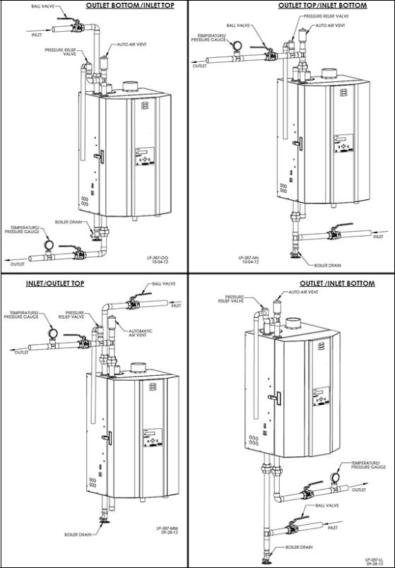
Figure 7 – Near Boiler Piping* – NOTE: This drawing is meant to show system piping concept only. Installer is responsible for all equipment and detailing required by local codes. *Top / Bottom Supply / Return Connections available on 155, 199, 285, and 399 Models ONLY.
NOTE: In piping applications utilizing a single zone, it is recommended that the installer use flow / check valves with weighted seats at or near the boiler to prevent gravity circulation.
WHL-016 REV. 3.4.15
24
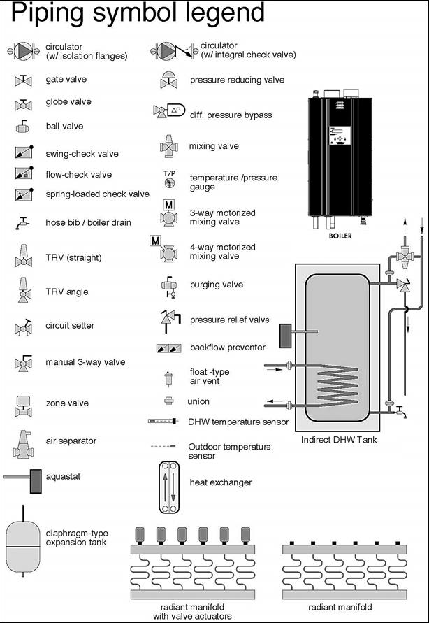
Figure 8 – Piping Symbol Legend
WHL-016 REV. 3.4.15
25
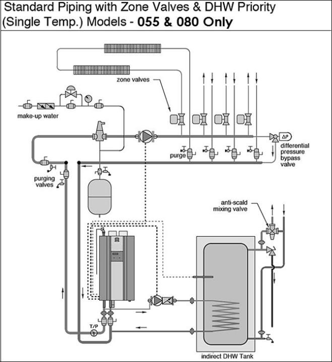
Figure 9 – Standard Piping with Zone Valves and DHW Priority - NOTES:
1.This drawing is meant to show system piping concept only. Installer is responsible for all equipment and detailing required by local codes.
2.All closely spaced tees shall be within 4 pipe diameters center to center spacing.
3.A minimum of 6 pipe diameters of straight pipe shall be installed upstream and downstream of all closely spaced tees.
4.The minimum pipe size for connecting a indirect water heater is 1”
5.The minimum pipe size for connecting an 055 or 080 - 1”.
6.Circulators are shown with isolation flanges. The alternative is standard flanges with full port ball valves. Purge valves can be used with circulator flanges as an alternative.
7.A mixing valve is recommended if the DHW temperature is set above the factory setting of 119oF.
8.Piping shown is Standard. VERY IMPORTANT: Minimum flow rates outlined in the manual must be maintained to minimize short cycling.
9.Install a minimum of 12 diameters of straight pipe upstream of all circulators.
WHL-016 REV. 3.4.15

26
Figure 10 - Standard Piping with Pumps and DHW Priority - NOTES:
1.This drawing is meant to show system piping concept only. Installer is responsible for all equipment and detailing required by local codes.
2.All closely spaced tees shall be within 4 pipe diameters center to center spacing.
3.A minimum of 6 pipe diameters of straight pipe shall be installed upstream and downstream of all closely spaced tees.
4.The minimum pipe size for connecting a indirect water heater is 1”
5.The minimum pipe size for connecting an 055 or 080 - 1”.
6.Circulators are shown with isolation flanges. The alternative is standard flanges with full port ball valves. Purge valves can be used with circulator flanges as an alternative.
7.A mixing valve is recommended if the DHW temperature is set above the factory setting of 119oF.
8.Piping shown is Standard.
9.Install a minimum of 12 diameters of straight pipe upstream of all circulators.
10.VERY IMPORTANT – Minimum flow rates outlined in this manual must be maintained through the heat exchanger to minimize short cycling.
WHL-016 REV. 3.4.15
27
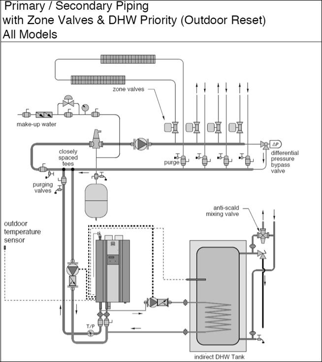
Figure 11 – Primary/Secondary Boiler Piping – Zone Valves and DHW Priority – Outdoor Reset - NOTES:
1.This drawing is meant to show system piping concept only. Installer is responsible for all equipment and detailing required by local codes.
2.All closely spaced tees shall be within 4 pipe diameters center to center spacing.
3.A minimum of 6 pipe diameters of straight pipe shall be installed upstream and downstream of all closely spaced tees.
4.The minimum pipe size for connecting a indirect water heater is 1”
5.The minimum pipe size for connecting an 055/080/110 - 1”, 155/199/285 – 1.25”, 399 – 1.5”.
6.Circulators are shown with isolation flanges. The alternative is standard flanges with full port ball valves. Purge valves can be used with circulator flanges as an alternative.
7.A mixing valve is recommended if the DHW temperature is set above the factory setting of 119oF.
8.Piping shown is Primary/Secondary. System flow (secondary loop) must be greater than the boiler’s primary loop flow.
9.Install a minimum of 12 diameters of straight pipe upstream of all circulators.
10.VERY IMPORTANT – Minimum flow rates outlined in this manual must be maintained through the heat exchanger to minimize short cycling.
WHL-016 REV. 3.4.15
 Loading...