


Owner’s Manual (page 2)
Read this manual for complete instructions
Manuel de l’utilisateur (page 12)
Lire ce manuel pour obtenir des directives complètes
Manual del usario (página 22)
Lea este manual para obtener las instrucciones completas
1112 • Form No. 0530803D
Quick Start Guide • Guide de démarrage rapide • Guía rápida para comenzar
Setup • Montage • Disposición
1 |
2 |
3 |
Read all warnings
Lisez tous les avertissements Lea todas las advertencias
4
Secure the paint can
Fixer le contenant
Seguro de recipiente
Prepare material
Préparez la peinture
Prepare el material
5
Insert the suction tube
Insérer le tube d’aspiration Inserte el tubo de succión
Attach paint can lid
Installer le couvercle de peinture Monte la tapa de pintura
6 |
or |
Attach roller arm
Fixer le bras du rouleau
Acople el brazo del rodillo
7 |
8 |
|
|
9 |
|
|
= |
|
|
|
PAINT |
|
|
|
|
|
= |
2 |
1 |
|
|
|
||
|
|
|
|
Plug in, switch to “PAINT” |
Adjust speed control |
Press and release to start |
||
Branchez, mettre l’interrupteur à la |
Réglez le contrôle de vitesse |
Appuyer et lâcher pour démarrer |
||
position “PAINT” |
Ajuste el control de velocidad |
Presione y suelte para arrancar |
||
Conecte, cambie el interruptor a la |
||||
|
|
|
||
posición “PAINT” |
Español |
Français |
English |
|
|
||||
ImportantSafety Safety
Information
Read all safety information before operating
the equipment. Save these instructions
This symbol indicates a hazardous situation, which, if not not avoided could result in death or serious injury.
To reduce the risks of fire or explosion, electrical shock and the injury to persons, read and understand all instructions included in this manual. Be familiar with the controls and proper usage of the equipment.
HAZARD: EXPLOSION OR FIRE
Solvent and paint fumes can explode or ignite, causing property damage and/or severe injury.
PREVENTION:
• Exhaust and fresh air introduction must be provided to keep the air within the work area free from accumulation of flammable vapors.
•Avoid all ignition sources such as static
electricity sparks, open flames, pilot lights, hot objects, cigarettes, and sparks from connecting and disconnecting power cords or working light switches.
•Fire extinguishing equipment must be present and in working order.
•Do not use materials with a flashpoint below 100° F (38° C). A fluid’s flashpoint is the temperature at which vapors from the fluid could ignite if exposed to a flame or spark. Consult your paint supplier for information about a fluid’s flashpoint.
•Keep the unit in a well ventilated location away from the work area. The pump contains arcing parts which emit sparks.
HAZARD: HAZARDOUS VAPORS
Paints, solvents, insecticides, and other materials may be harmful if inhaled, causing severe nausea, fainting, or poisoning.
PREVENTION:
•Use a respirator or mask whenever there is a chance that vapors may be inhaled. Read all instructions with the mask to insure that it will provide the necessary protection against the inhalation of harmful vapors.
HAZARD: GENERAL
May cause property damage or severe injury. PREVENTION:
•Read all instructions and safety precautions before operating any equipment. Never leave the unit running while unattended. Unplug whenever not in use.
•Never immerse the unit into any liquid.
•Comply with all appropriate local, state and national codes governing ventilation, fire prevention, and operation.
•This paint roller system is designed to be used with authorized parts only. When using this system with parts that do not comply with the minimum specifications and safety devices of the system manufacturer, the user assumes all risks and liabilities.
•Before each use, check all hoses for cuts, leaks, abrasion or bulging of cover or damage or movement of couplings. If any of these conditions exist, call
Customer Service.
Additional warnings are contained on the tag molded to the electrical cord of the unit. Be sure to read this tag before operating the unit.
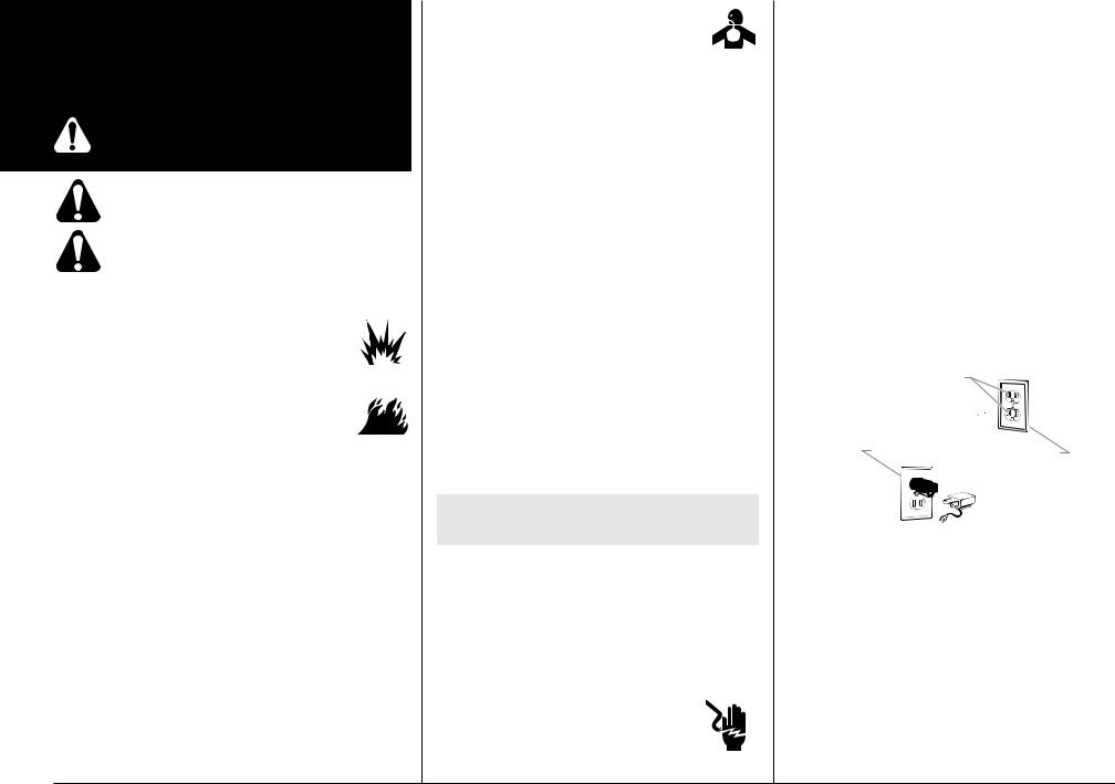
Grounding Instructions
This product must be grounded. In the event of an electrical short circuit, grounding reduces the risk of electric shock by providing an escape wire for the electric current. This product is equipped with a cord having a grounding wire with an appropriate grounding plug. The plug must be plugged into an outlet that is properly installed and grounded in accordance with all local codes and ordinances.
WARNING - Improper installation of the grounding plug can result in a risk of electric shock.
If repair or replacement of the cord or plug is necessary, do not connect the green grounding wire to either
flat blade terminal. The wire with insulation having a green outer surface with or without yellow stripes is the grounding wire and must be connected to the grounding pin.
Check with a qualified electrician or serviceman if the grounding instructions are not completely understood, or if you are in doubt as to whether the product is properly grounded. Do not modify the plug provided. If the plug will not fit the outlet, have the proper outlet installed by a qualified electrician.
This product is for use on a nominal 120 volt circuit and has a grounding plug that looks like the plug illustrated below. A temporary adapter which looks like the adapter illustrated in the figure below may be used to connect this plug to a 2 pole receptacle as shown if a properly grounded outlet is not available.
The temporary adapter should be used only until a properly grounded outlet as shown below can be installed by a qualified electrician. The green colored rigid ear lug or the grounding wire extending from the adapter must be connected to a permanent ground such as a properly grounded outlet box cover. Whenever the adapter is used, it must be held in place by a metal screw.
Grounded Outlet
Grounding Pin
Cover for grounded outlet box
Metal Screw
 Adapter

 Tab for
Grounding Screw
Extension Cord Selection
If an extension cord is used, make sure that it is of the 3-conductor type with NEMA connectors so a continuous grounding circuit is provided from the tool to the power circuit receptacle. Make sure your extension cord is in good condition. Also, be sure that the conductor size is large enough to prevent excessive voltage drop which will cause loss of power and possible motor damage to the unit. A 14 or 12 gauge cord is recommended.
If an extension cord is to be used outdoors, it must be marked with the suffix W-A following the cord type designation. For example, SJTW-A to indicate that it is acceptable for outdoor use.
English |
2 |
|
|
|
|

Parts and |
a |
c |
e |
0 |
9 |
|
|
|
h1 |
|
|
Variable Speed |
|
|
|
|
|
|
|
|
Components |
b |
|
|
|
|
|
h2 |
|
f |
|
|
||
Note: Some parts are not |
|
|
|
|
||
|
|
|
|
|
||
assembled out of the box. See |
|
d |
|
|
|
|
“Setup” section, page 4. |
|
|
|
|
||
|
|
|
|
|
||
Start |
General Description: |
h3 |
|
|
|
|
|
|
|
|
|
||
This high performance power roller is a |
|
Paint can shown |
|
|
|
|
|
|
precision power tool used for both interior and |
|
|
|
|
|
|
|
|
exterior painting and may be used with both |
|
for reference only. |
|
|
|
|
|
|
water (latex) and oil based paints. |
|
Not included. |
|
|
|
|
|
|
important: Use of oil-based paints must |
|
|
|
|
|
|
|
|
be limited to only those paints which can be |
|
|
|
|
|
|
|
|
cleaned with mineral spirits. Latex paints |
|
|
|
|
|
|
|
|
can be cleaned with soapy, lukewarm water. |
|
|
|
|
|
|
|
|
DO NOT use hot water when cleaning or |
|
|
|
|
f |
|
|
|
flushing the unit. |
|
o |
|
e |
|
|
|
|
Note: Some of the parts listed on this page |
|
|
|
|
|
|
||
can be replaced by calling technical service. |
|
|
|
|
|
|
|
m |
See page 32 for part numbers. |
|
|
|
i |
|
|
|
|
Specifications: |
|
|
|
|
|
|
|
|
|
|
|
|
|
l |
|
n |
|
Flow rate: 8 - 20 fluid oz. per minute (flow rate |
|
|
|
|
|
|
||
will depend on thickness of paint) |
|
|
|
|
j |
k |
|
|
Power source: 120 VAC |
|
|
|
|
|
|
|
|
Power requirement: 60 Hz current. |
|
g |
|
|
|
|
|
|
Capability: Most oil and water based paints |
|
|
|
|
|
|
|
|
|
|
|
|
|
|
|
|
|
and stains. Do not use with lacquers, lacquer |
|
|
h |
|
|
|
|
|
thinners or any other solvent with a flash point |
|
o1 |
|
|
|
|
p |
|
below 100° F (38°C). |
|
|
|
|
|
|
j |
|
Questions? |
Item |
Description |
Item |
Description |
|
|
Item |
Description |
Call Wagner Technical Service at: |
|
|
||||||
a |
Roller rest area |
h |
9” Roller assembly |
|
l |
Roller handle |
||
1-800-760-3844 |
|
|||||||
b |
Can lid |
|
h1 - 3/8” nap roller cover |
|
m |
Hose |
||
|
|
|
||||||
Register your product online at: |
c |
Suction tube |
|
h2 - Roller cap |
|
|
n |
Extension |
d |
Tower |
|
h3 - Roller core |
|
|
o |
Smart Edge™ Roller |
|
www.wagnerspraytech.com |
e |
Variable speed dial |
i |
Roller arm |
|
|
|
o1 - Roller cover |
|
f |
Paint flow reverse switch |
j |
Quick-release tabs |
|
p |
3/4” nap roller cover |
|
|
g |
Spatter shield |
k |
Handle button |
|
|
|
|
3 |
English |
|
Setup
Start Material Preparation:
Make sure the material you plan on using is thoroughly stirred and free from debris. Strain if necessary. Any impurities in the material can cause clogs in the pump system or roller assembly.
Note: If you plan to use material that is contained in anything but a round, one gallon container, you will not be able to attach the container to the unit. Refer to the Accessories section, page 32, to order parts that are compatible with other types of paint containers.
Roller handle rest area:
Use the carrying handle as a rest area for the roller handle and arm when they are not in use.
Note: The roller handle should not be placed into the handle rest area when it is attached to the extension! The spatter shield can be used as a rest for the roller arm when the extension is being used.
Note: During break periods, make sure that the roller is not saturated with paint, or it will drip and accumulate in the spatter shield.
1 |
(a) |
|
 (b)
(b)
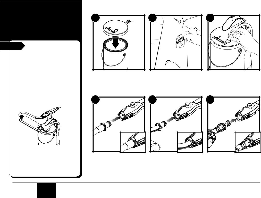
1. Tightly place the paint can lid on the paint can.
Align arrow (a) and paint can handle (b) as shown.
2
 (c)
(c)
2. Place paint can on the base and insert the lid tab onto the opening on the tower.
Press the tab over the tower post (c).
3
3. Insert the suction tube until it reaches the bottom of the paint can.
4 |
4. If using the extension, press the quick-release tabs on the handle and insert the extension into the handle.
Make sure they are securely fastened.
5 |
5. Press the quick-release tabs on the handle and attach the roller arm assembly to the handle (or extension).
Make sure they are securely fastened.
6 |
6. If using the Smart Edge Roller assembly, press the quickrelease tabs on the handle and attach the Smart Edge Roller to the handle (or extension).
English |
4 |
|
 Loading...