


 Loading...
R
505
HIGH PERFORMANCE 


 AIRLESS SPRAYER


 OWNER'S MANUAL


Easy Does It From Set Up to Clean Up
Read Warnings |
Assemble Cart |
Attach Tip to Gun |
Attach Return Hose |
Attach Paint Hose |
|
Prepare to Prime |
|
Attach Suction Set |
|
|
Prime Pump |
|||||||||
|
|
|
|
|
|
|
|
|
|
|
|
|
|
|
|
|
|
|
|
|
|
|
|
|
|
|
|
|
|
|
|
|
|
|
|
|
|
|
|
|
|
|
|
|
|
|
|
|
|
|
|
|
|
|
|
|
|
|
|
|
|
|
|
|
|
|
|
|
|
|
|
|
|
|
|
|
|
|
|
|
|
|
|
|
|
|
|
|
|
|
|
|
|
|
|
|
|
|
|
|
|
|
|
|
|
|
|
|
|
|
|
|
|
|
|
|
|
|
|
|
|
|
|
|
|
|
|
|
|
|
|
|
|
|
|
|
|
|
|
|
|
|
|
|
|
|
|
|
|
|
|
|
Set Pressure |
Spray |
Short Term Storage OR |
Clean Up |
Maintenance |
Optional Hopper Accessory |
PRINTED IN THE U. S. A. |
1 |
Questions? ... Need Help?
Wagner maintains a toll-free help line for you should you have any comments or problems with this Wagner product. Call us first ....for answers fast...
Wagner Technical Service
1-800-328-8251
Hours: Weekdays: 8:00 - 4:30 Central Time
Weekends: 9:00 - 4:00 Central Time
Form No. 0270993-11/93
CONTENTS
General Description ....................................................... |
2 |
Short Term Storage ...................................................... |
19 |
Safety Precautions ...................................................... |
3-6 |
Cleanup and Long Term Shutdown ........................ |
20-22 |
Extension Cord............................................................... |
7 |
Maintenance........................................................... |
23, 24 |
Grounding Instructions ................................................... |
7 |
Optional Hopper ........................................................... |
25 |
Pressure Relief Procedure ............................................. |
8 |
Trouble Shooting .................................................... |
26, 27 |
Set Up ....................................................................... |
9-11 |
Parts Lists ............................................................... |
28-30 |
Priming .................................................................... |
12-14 |
Accessories List ........................................................... |
31 |
Spraying .................................................................. |
15-18 |
Warranty........................................................ |
Back Cover |
Components:
The shipping carton for your 505 Painting System Cart frame with wheels, motor and pump attached. Cart handle
Pail bracket/cart foot Suction set and return tube Spray gun and filter
Spray tip and gasket
Three bolts, washers and wing nuts 25-foot 3/16-inch higher pressure hose
contains the following components:
Spare Outlet Spring, P/N 0047485
Spare Tip Seal , P/N 0156713
Return tube fitting , P/N 0088715
Operator’s manual
ARE LOCATED IN THE
LITERATURE SET WITH
REGISTRATION CARD
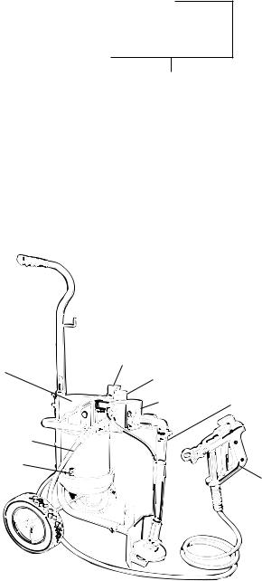
General Description
The Wagner 505 High Performance Airless Sprayer is a precision power tool used for spraying many types of materials. It is a relatively simple machine to operate, however, a basic understanding of its components is necessary.
Read and follow this instruction manual carefully for proper operating instructions, maintenance and safety information.
Specifications
Weight: ................................................... |
27 lbs. (12 kg ) |
Capacity: ............................................... |
Up to 1/3 gallon |
|
(1-1/4 liters) per minute |
Power Source: ............................ |
1/3 HP Electric Motor, |
|
totally enclosed, fan cooled. |
Power Requirement: |
......................... 15 amp minimum |
|
circuit on 115 VAC, 60 HZ current. |
|
Generator – 15 amp A/C. |
Spraying Pressure: .............................. |
Up to 2,500 psi. |
Safety Features: .................. |
Spray gun safety lock and |
|
pressure diffuser; built-in tip safety |
|
guard; priming knob for safe |
|
pressure release. |
Portability: ........................ |
Compact design, light weight |
|
for easy movement. |
Capability: ............................ |
Sprays a variety of paints, |
oil base, latex, primers, stains, preservatives and other nonabrasive materials, including pesticides and liquid fertilizers.
Pressure Control
Knob
Hydraulic Pump
Priming Knob
Paint Block |
Suction Set |
Paint Hose
On/Off Switch
Spray Gun
Figure 1 – Wagner 505 Airless Sprayer
2
SAFETY PRECAUTIONS
This manual contains information which must be read and understood before using the equipment. When you come to an area which has one of the following symbols, pay particular attention and make certain to heed the safeguard.
 WARNING
Important safety information indicates a hazard which may cause serious injury or loss of life.

 CAUTION
Important information that tells how to prevent damage to equipment or how to avoid causes of minor injuries.
Notes: Gives important information which should be given special attention.

 CAUTION
THIS UNIT IS PROVIDED WITH A THERMALLY PROTECTED AUTOMATIC RESET. IF AN OVERLOAD OCCURS THE THERMALLY PROTECTED AUTOMATIC RESET DISCONNECTS THE MOTOR FROM THE POWER SUPPLY.
•Motor will restart without warning when protector automatically resets.
•Always disconnect motor from power supply before working on equipment.
•When thermally protected automatic reset disconnects the motor from the power supply, relieve pressure by turning priming valve to "prime" A .
•Turn ON-OFF switch OFF.
CAUTION: THE CAUSE OF THE OVERLOAD SHOULD BE CORRECTED BEFORE RESTARTING. (SEE TROUBLE SHOOTING )
3

 WARNING
HAZARD |
PREVENTION |
Injection Injury - A high pressure stream of paint produced by this equipment can pierce the skin and underlying tissues, leading to serious injury and possible amputation.
DO NOT TREAT AS A SIMPLE CUT! Injectioncan lead to amputation. See a physician immediately.
NOTE TO PHYSICIAN: Injection into the skin is a traumatic injury. It is important to treat the injury surgically as soon as possible. DO NOT delay treatment to research toxicity. Toxicity is a concern with some coatings injected directly into the blood stream. Consultation with a plastic surgeon or reconstructive hand surgeon may be advisable.
•Maximum operating range of the gun - 2500 PSI fluid pressure.
•NEVER aim the gun at any part of the body.
•NEVER allow any part of the body to come in contact with the fluid stream. DO NOT come in contact with a fluid stream created by a leak in the fluid hose.
•NEVER put hand in front of the gun. Gloves will NOT provide protection against an injection injury.
•ALWAYS lock the gun trigger,shut fluid pump off and release all pressure before servicing, cleaning tip guard, changing tips, or leaving unattended. Simply turning off the electrical power will not release pressure in the system. The Prime Spray Valve must be turned to the prime A position to relieve the pressure.
•ALWAYS have the tip guard in place while spraying. The tip guard provides some protection against injection injuries but is mainly a warning device.
•ALWAYS remove spray tip before flushing or cleaning the system. Refer to Cleaning Instructions.
•Paint hose can develop leaks from wear, kinking, abuse etc. A leak is capable of injecting material into the skin. The paint hose should be inspected before each use.
•NEVER use a spray gun which does not have a trigger lock and trigger guard in place and in working order.
•All accessories must be rated at or above 2500 P.S.I. (Includes spray tips, guns, extensions, and hose).
•In case of skin injection see physician immediately.
4

 WARNING
HAZARD |
PREVENTION |
Explosion or fire - Solvent and paint fumes can explode or ignite, causing property damage and or severe injury.
•Exhaust and fresh air introduction must be provided to keep the air within the spray area free from accumulation of flammable vapors.
•Avoid all ignition sources such as static electricity sparks, open flames such as pilot lights, hot objects such as cigarettes, and sparks from connecting and disconnecting power cords and working light switches.
•Fire extinguishing equipment must be present and in working order.
•Keep the pump away from spray area to avoid solvent and paint fumes. The pump contains arcing parts which emit sparks.
•Do not spray paints and other inflammable fluids which have a flashpoint below 21° C (70° F). (Flashpoint is the temperature at which a fluid begins giving off a sufficient amount of flammable vapor that could ignite when exposed to a flame or spark.)
•High velocity flow of material through equipment may develop static electricity. The equipment being used, and objects in and around the spray area must be properly grounded to prevent static discharge and sparks.
•Use only conductive or grounded high pressure fluid hoses for airless applications. Be sure that gun is grounded through hose connections.
•Power cord must be connected to a grounded circuit. (See proper grounding instructions.)
•Follow the material and solvent manufacturer's safety precautions and warnings.
•WHEN FLUSHING EQUIPMENT use lowest possible pressure.
5

 WARNING
HAZARD |
PREVENTION |
|
|
Explosion hazard incompatible materials - May cause property damage or severe injury.
•DO NOT USE BLEACH.
•DO NOT use halogenated hydrocarbon solvents.
•Halogenated hydrocarbon solvents such as methylene chloride and 1,1,1 - Trichlorethane are not compatible with aluminum and may cause an explosion. If unsure of a material’s compatibility with aluminum, contact your coatings supplier.
Hazardous vapors - Paints, solvents, insecticides, and other materials may be harmful if inhaled causing severe nausea, fainting, or poisoning.
•Use a respirator or mask whenever there is a chance that vapors may be inhaled. Read all instructions with the mask to insure that it will provide the necessary protection against the inhalation of harmful vapors.
General - May cause property damage or severe injury.
•Read all instructions and safety precautions before operating.
•Comply with all appropriate local, state and national codes governing ventilation, fire prevention, and operation.
•The United States Government Safety Standards have been adopted under Occupational Safety and Health Act. These standards, particularly the General Standards, Part 1910 and construction Standard, Part 1926, should be consulted.
•This high pressure airless pump is designed to be used with authorized parts only. When using this pump with parts that do not comply with the minimum specifications and safety devices of the pump manufacturer, the user assumes all risks and liabilities.
•Before each use, check all hoses for cuts, leaks, abrasion or bulging of cover or damage or movement of couplings. If any of these conditions exist, replace the hose immediately. Never repair a paint hose. Replace it with another grounded hose.
•All hoses, swivels, guns, and accessories used with this unit must be pressure rated at or above 2500 PSI.
• DO NOT spray on windy days.
6
Extension Cord
Use only a 3-wire extension cord that has a 3-blade grounding plug and a 3-slot receptacle that will accept the plug on the product. Make sure your extension cord is in good condition. When using an extension cord, be sure to use one heavy enough to carry the current your product will draw. An undersized cord will cause a drop in line voltage resulting in loss of power and overheating. A 14 or 12 gauge cord is recommended.
NOTE: More than 100 feet of extension cord is not recommended. Use more paint hose, not more extension cord. Shorter extension cords will assure maximum electrical power for proper operation.
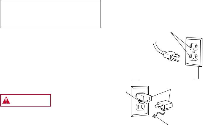
Grounding Instructions
This product must be grounded. In the event of an electrical short circuit, grounding reduces the risk of electric shock by providing an escape wire for the electric current. This product is equipped with a cord having a grounding wire with an appropriate grounding plug. The plug must be plugged into an outlet that is properly installed and grounded in accordance with all local codes and ordinances.
Improper installation of the
WARNINGgrounding plug can result in a risk of electric shock.
If repair or replacement of the cord or plug is necessary, do not connect the green grounding wire to either flat blade terminal. The wire with insulation having an outer surface that is green with or without yellow stripes is the grounding wire and must be connected to grounding pin.
Check with a qualified electrician or serviceman if the grounding instructions are not completely understood, or if in doubt as to whether the product is properly grounded. Do not modify the plug provided; if it will not fit the outlet, have the proper outlet installed by a qualified electrician.
This product is for use on a nominal 120 volt circuit, and has a grounding plug that looks like plug illustrated in Figure 2
(A) below. A temporary adapter which looks like the adapter illustrated in Figure 2 (B) and (C), may be used to connect this plug to a 2 pole receptacle as shown in Figure 2 (B) if a properly grounded outlet is not available. The temporary adapter should be used only until a properly grounded outlet as shown in Figure 2 (A) can be installed by a qualified electrician. The green colored rigid ear lug, or the like extending from the adapter must be connected to a permanent ground such as a properly grounded outlet box cover. Whenever the adapter is used, it must be held in place by a metal screw.
Grounded
Outlet
Grounding Pin 
(A)
Cover of Grounded Outlet Box
Adapter
Metal
Screw
(C)
(B)
Tab for Grounding Screw
Figure 2 – Grounding Methods
7
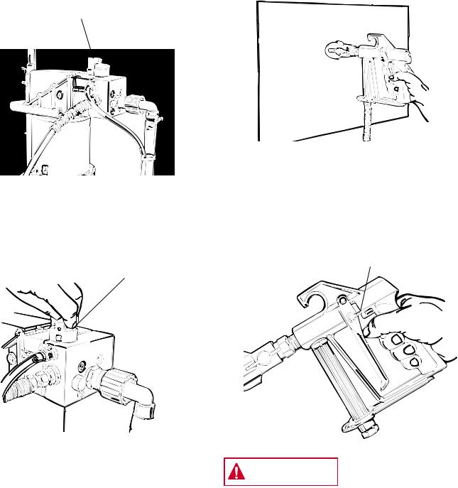
Pressure Relief Procedure
Follow this procedure after the unit is assembled and before any operation which involves the spray gun such as changing tips or accessories, or cleaning and maintenance.
1. Make sure PRESSURE CONTROL KNOB is at its lowest setting (counterclockwise).
Pressure Control
Knob
3.Trigger gun to remove any pressure which may still be in the hose.
2. Turn PRIMING KNOB to PRIME A position. |
4. Lock gun trigger in the Off position. |
|
Prime A |
Trigger Lock |
|
Spray B |
||
|
||
Knob |
|
Injection hazard possible. Do
WARNINGnot spray without tip guard in
place. NEVER trigger gun unless tip is completely turned to the spray or unclog position. ALWAYS engage trigger lock before removing, replacing or cleaning tip.
8
SET-UP
ASSEMBLE CART
Tools needed:
Some assembly is required to get your Wagner 505 Airless Sprayer ready to go. You will need two adjustable wrenches, a screw driver and a pair of pliers.
NOTE: Sprayer should remain unplugged during assembly.
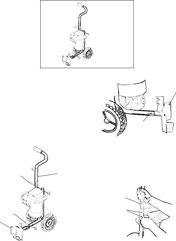
1.Slide pail bracket (1) onto cart frame and attach with one bolt, washer and wing nut (2). See Figure 2 and Figure 3 A. This bracket helps to keep the sprayer stable in addition to providing a rest for the paint bucket and a catch for the bucket handle.
Pail Bracket
Bolt, washer and wing nut
Figure 3A - Attaching Pail Bracket
|
|
2. Attach cart handle (3). Face the hose hook toward the |
|
|
front of the unit. Use two bolts, washers and wing nuts |
4 |
3 |
(4), tightening securely. See Figure 3B. |
|
|
Cart Handle |
2 |
Bolt, washer |
and wing nut |
1
Figure 2 – Cart Assembly Diagram |
Figure 3B - Attaching Cart Handle |
9
SET-UP
ATTACH TIP TO GUN
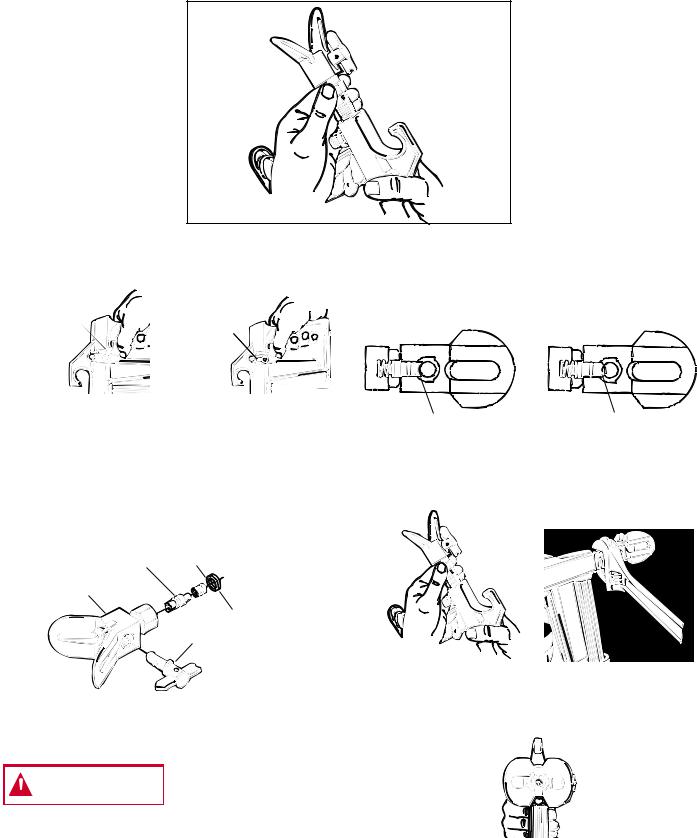
1. Lock gun. See Figure 4.
Locked
Position
Unlocked
Position
Figure 4 - Gun in Locked & Unlocked Position
2.If spray tip is not preassembled, (See Figure 5) insert tip (1) into tip guard, (2) and turn 90° counterclockwise to spray position (arrow pointing away from gun). Cylinder of tip forms a stop for the seal (3). Insert seal (3) aligning the curve of the seal with the curve of the tip.
3 4
2
Red Seal
1
Figure 5 – Spray Tip Assembly
WARNING POSSIBLE INJECTION  HAZARD. Do not spray without tip guard in place. Never trigger gun unless tip is in the spray or unclog position. Always engage trigger lock
before removing, replacing or cleaning tip.
3.Check seal alignment by removing tip and inspecting tip guard visually, See Figure 6. If needed, remove seal (3) and replace until properly aligned. Replace tip to spray position, (arrow away from gun). Insert red seal (4).
Correct Way |
Wrong Way |
Figure 6 - Spray Tip Assembly
4.Attach spray tip to gun. Tighten nut first by hand, then tighten with a wrench. See Figure 7.
Figure 7- Attach Tip to Gun
NOTE: When attaching tip to gun, align tip guard as shown in Figure 8. Then tighten with wrench.
Figure 8 - Vertical Tip Pattern
10
Loading...