


 HVLP
HVLP
ConversionGun
pistoletpulvÉrisateurbi-usage pistoladeconversiÓn
Owner’sManual•Manueldel’utilisateur•Manualdelusario
Questions?•Besoind’aide?•¿Necesitaayuda?
Call Wagner Technical Service at:
Appelez le service technique Wagner :
Llame Wagner Technical Service al:
1-800-880-0993
Register your product online at:
Enregistrement du produit en ligne sur le site : Regístrelo del producto en línea en:
www.wagnerspraytech.com
NOTE: This manual contains important warnings and instructions. Please read and retain for reference.
1012 • © Wagner Spray Tech. All Rights Reserved. Form No. 0529832A
Important Safety Information · Read all safety information before operating the equipment. Save these instructions.
Indicates a hazardous situation which, if not avoided, could result in death or serious injury.
To reduce the risks of fire or explosion, electrical shock and the injury to persons, read and understand all instructions included in this manual. Be familiar with the controls and proper usage of the equipment.
HAZARD: EXPLOSION HAZARD DUE TO
INCOMPATIBLE MATERIALS
Will cause property damage or severe injury.
PREVENTION:
•Do not use materials containing bleach or chlorine.
•Do not use halogenated hydrocarbon solvents such as bleach, mildewcide, methylene chloride and 1,1,1 - trichloroethane. They are not compatible with aluminum.
•Contact your coating supplier about the compatibility of material with aluminum.
HAZARD: GENERAL
Can cause severe injury or property damage.
PREVENTION:
•Read all instructions and safety precautions before operating any equipment.
•Follow all appropriate local, state, and national codes governing ventilation, fire prevention, and operation.
•The United States Government Safety Standards have been adopted under the Occupational Safety and Health Act (OSHA). These standards, particularly Part 1910 of the General Standards and Part 1926 of the Construction Standard should be consulted.
•Use only manufacturer authorized parts. User assumes all risks and liabilities when using parts that do not meet the minimum specifications and safety devices of the manufacturer.
•Before each use, check all hoses for cuts, leaks, abrasion or bulging of cover. Check for damage or movement of couplings. Immediately replace the hose if any of these conditions exist. Never repair a hose.
Replace it with an identical replacement hose.
•Do not spray outdoors on windy days.
•Wear clothing to keep paint off skin and hair.
•Never aim the spray gun at any part of the body.
HAZARD: HAZARDOUS VAPORS
Paints, solvents, insecticides, and other
materials can be harmful if inhaled or come in contact with the body. Vapors can cause severe nausea, fainting, or poisoning.
PREVENTION:
•Use a respirator or mask if vapors can be inhaled. Read all instructions supplied with the mask to be sure it will provide the necessary protection.
•Wear protective eyewear.
•Wear protective clothing as required by coating manufacturer.
HAZARD: EXPLOSION OR FIRE
Solvent and paint fumes can explode or ignite. Property damage and/or severe injury can occur.
PREVENTION:
•Provide extensive exhaust and fresh air introduction to keep the air within the spray area free from accumulation of flammable vapors.
•Avoid all ignition sources such as static electric sparks, open flames, pilot lights, and hot objects. Connecting or disconnecting power cords or working light switches can make sparks.
•Do not smoke in spray area.
•Fire extinguisher must be present and in good working order.
•The power cord must be connected to a grounded circuit.
•Follow the material and solvent manufacturer’s safety precautions and warnings.
•Use extreme caution when using materials with a flashpoint below 70° F (21° C). Flashpoint is the temperature that a fluid can produce enough vapors to ignite.
•Plastic can cause static sparks. Never hang plastic to enclose a spray area. Do not use plastic drop cloths when spraying flammable materials.
Table of Contents |
|
Safety................................................................................................ |
2 |
Introduction...................................................................................... |
3 |
Using an HVLP Spray Gun............................................................. |
3-4 |
Preparing to Spray........................................................................................ |
3 |
Selecting a Spray Pattern........................................................................... |
3 |
Spray Pattern Size......................................................................................... |
4 |
Adjusting the Material Flow...................................................................... |
4 |
Spraying............................................................................................................ |
4 |
Adjusting the Suction Tube....................................................................... |
4 |
Cleaning the Spray Gun................................................................... |
5 |
Maintenance.................................................................................. |
5-7 |
Adjusting the Packing Nut......................................................................... |
5 |
Replacing the Needle Packing and Air Valve Seals........................... |
5 |
Replacing the Check Valve, Valve Seal, and Air Tubes..................... |
6 |
Replacing the Cup Gasket.......................................................................... |
7 |
Converting to a Single Pin Trigger.................................................. |
7 |
Choosing a Projector Set................................................................. |
7 |
Changing a Projector Set............................................................................ |
7 |
Optional Accessories........................................................................ |
8 |
Material reduction/projector set chart........................................... |
9 |
Troubleshooting.............................................................................. |
9 |
Regulator Cup Gun Parts List.................................................. |
26–27 |
Français........................................................................................... |
10 |
Español............................................................................................ |
18 |
Warranty......................................................................................... |
28 |
English |
2 |
© Wagner Spray Tech. All rights reserved. |
|
|
|
Introduction
This spray gun is designed for use as a High Volume/Low Pressure (HVLP) painting system.
With an HVLP system, the highest quality professional finish can be achieved with little preparation or setup time. HVLP systems are not intended to replace airless systems. Instead, they are meant to compliment airless by improving the final finish on the substrate, minimizing waste, and reducing labor time.
This HVLP spray gun with regulator is designed to be used with an air compressor. Please review all the information contained in this manual before operating your HVLP spray gun.
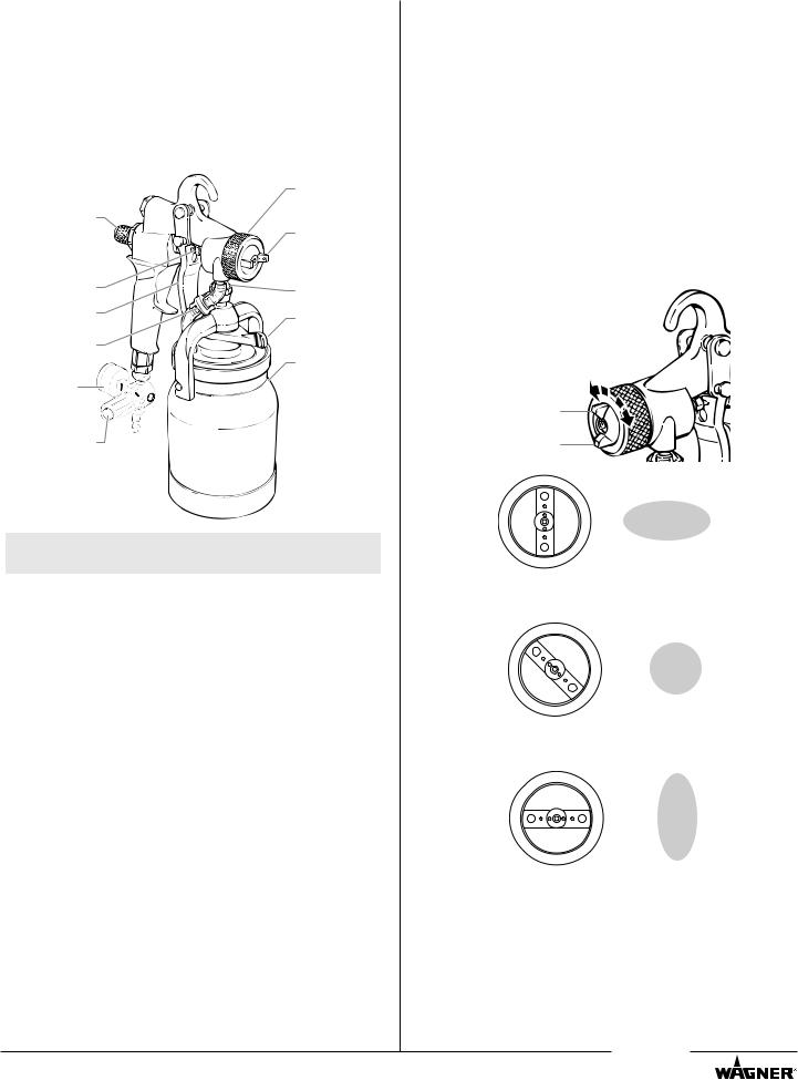
Air Cap Ring
Material Flow |
|
Adj. Knob |
Air Cap |
|
|
Packing Nut |
Fluid Inlet |
|
|
Trigger |
Cup Locking |
|
|
Check Valve |
Lever |
|
|
|
1-Quart Cup |
Pressure |
Assembly |
|
|
Gauge |
|
Regulator |
|
Note: The cup locking lever secures the cup to the spray gun.
Using an HVLP Spray Gun
Preparing to Spray
1.Release the cup locking lever and remove the cup.
2.Make sure that the cup and the cup gasket is clean and in position. Fill the cup with the desired painting material.
3.Place the cup on the spray gun and tighten the cup locking lever.
4.Attach the air supply hose to the air inlet fitting at the bottom of the gun handle.
5.Turn on the air supply.
Selecting a Spray Pattern
The spray pattern is adjusted by turning the air cap into either a vertical, horizontal, or diagonal position. To turn the air cap, grasp the two front tabs and twist. Never trigger the gun while adjusting the spray pattern.
Air Cap Tabs 
Vertical |
Horizontal |
Tip Position |
Pattern |
Diagonal |
Round |
Tip Position |
Pattern |
Horizontal |
Vertical |
Tip Position |
Pattern |
© Wagner Spray Tech. All rights reserved. |
3 |
English |
|
|
|

Spray Pattern Size
To change the spray pattern size without changing the spray pattern shape, turn the air cap ring.
Smaller |
Bigger |
Pattern |
Pattern |
Air Cap Ring |
|
Turning the ring clockwise will make the pattern bigger. Turning the ring counterclockwise will make the pattern smaller. As you reduce the spray pattern size, you will need to move closer to the surface.
Adjusting the Material Flow
Each individual job and material may require slight adjustments in the material flow.
Turn the material flow adjustment knob clockwise for less fluid and counterclockwise for more fluid.
Material Flow 

Adjustment Knob
More |
Less |
Fluid |
Fluid |
Spraying
Hold the spray gun between 1 and 8 inches from the spraying surface, depending on the size of the spray pattern that you need. The closer to the surface you hold the gun, the smaller the spray pattern.
Keep the gun at right angles to the spraying surface in order to apply an even coat of material. If you keep the spray gun moving at a smooth and constant speed, the spray material is less likely to run or sag.
Correct
Begin |
Trigger |
Even |
Release |
End |
pass |
gun |
stroke |
trigger |
pass |
Always squeeze the trigger of the spray gun after you begin your spray pass and release it before the pass is done. For best results, make the spray passes about 20 inches long and overlap each pass by 4 or 5 inches. Remember to keep the gun at right angles to the spraying surface.
Incorrect
Adjusting the Suction Tube
The suction tube on your spray gun lets you get the most out of the material in your cup no matter at what angle you need to spray.
NOTE: Before adding material to the cup, rotate the suction tube by hand to the desired direction.
a.If you are going to be spraying in a downward direction, the angled end of the suction tube should be pointing toward the front of the gun.
b.If you are going to be spraying in an upward direction, the angled end of the suction tube should be pointing toward the rear of the gun.
a |
b |
English |
4 |
© Wagner Spray Tech. All rights reserved. |
|
|
|
Cleaning the Spray Gun
It is very important to clean your HVLP spray gun thoroughly after each use.
1.Empty the spray material from the cup.
2.Pour a small amount of the appropriate solvent in the cup and attach the cup to the spray gun.
3.Shake and spray the gun in a well ventilated area.
NOTE: Do not restrict the nozzle when cleaning. Back flushing of the system is not necessary.
4.Repeat the steps above until the solvent appears clear.
5.Wipe the interior/exterior of the cup and the spray gun with the appropriate solvent until it is clean.
6.Remove the needle, fluid nozzle, and air cap and clean them thoroughly. Make sure that the air holes and material
passages are completely clean. Never use metal tools or picks to clean the air cap or nozzle.
important: Any attempt to remove the fluid inlet fitting will result in damage to the gun body and void the warranty.
NOTE: Remove the needle packing only when replacing with a new needle packing. Do not remove the needle packing for cleaning.
7.Disassemble, clean, and dry the check valve and air tubes after each use.
important: DO NOT clean the air tubes with hot solvents such as lacquer thinner. Hot solvents will damage the air tubes.
Note: Lubricate all of the threaded parts on the spray gun with petroleum jelly when you put them back
together. This will help keep them working properly.
important: Do not use any lubricants containing silicone. Silicone can cause problems when used with some paints.
Maintenance
Perform the following maintenance procedures to keep your HVLP spray gun working properly.
Adjusting the Packing Nut
If material leaks from around or through the packing nut, readjust the packing nut.
1.Disconnect the air hose from the air inlet and remove the cup assembly.
2.Pull the trigger all the way back and hold.
3.Tighten the packing nut using a 3/8 inch wrench until the needle remains retracted inside the nozzle when you release the trigger.
4. Loosen the packing nut slowly |
Packing Nut |
until the needle moves freely |
|
back into position in the nozzle. |
|
Once you have adjusted the nut, reconnect the air hose and the cup assembly. Squeeze the trigger to see if the leaking has stopped. If it has not, make sure the packing nut is as tight as possible, while allowing the needle to move freely. If adjusting the packing nut does not stop the leak, replace the packing.
Replacing the Needle Packing and Air Valve Seals
NOTE: Remove the needle packing only when replacing with a new needle packing. Do not remove the needle packing for cleaning.
The needle packing and the air valve seals can be replaced separately. If you are replacing only one of them, use the appropriate steps from the following procedures.
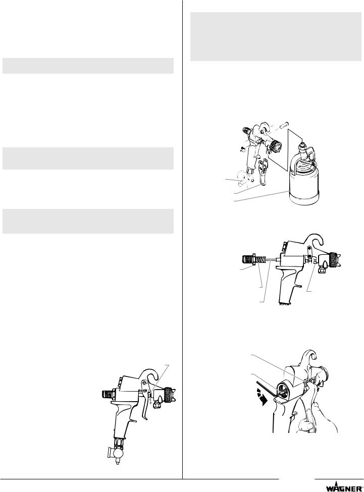
Removing the Needle and Housing
1.Disconnect the air hose from the air inlet.
2.Remove the material hose or cup assembly.
3.Remove the snap rings from the trigger retaining pins and slide the pins out of the gun.
4.Remove the trigger.


 Trigger
Retaining
Pins
Snap Rings

Regulator |
Trigger |
Cup Assembly
5.Loosen the packing nut using a 3/8 inch wrench.
6.Loosen and remove the material flow adjustment housing, needle, seal, and spring using a wrench.
Material
Adjustment
Housing
Seal and |
Packing Nut |
|
Spring |
||
|
||
Needle |
|
7.Insert an 1/8 inch hex wrench into the back of the needle guide shaft.
8.Hold the retaining nut with a wrench and turn the 1/8 inch hex wrench counterclockwise to remove the retaining nut.
9.Pull the needle guide shaft out of the gun body.
Retaining Nut
Needle
Guide Shaft
© Wagner Spray Tech. All rights reserved. |
5 |
English |
|
|
|
Replacing the Air Valve Seals
1.Remove the old rear air valve seal. It may stay on the end of the needle guide shaft spring or in the material flow adjustment housing.
2.Slide the new rear seal into the material adjustment housing.
3.Remove the front seal retaining clip using a snap-ring pliers.
4.Slide the old front air valve seal off of the needle guide shaft.
5.Place the new front air valve seal on the needle guide shaft with the beveled side facing the gun.
NOTE: Make sure that the new front air valve seal looks like the one that was just removed.
SIDE VIEW
Front Air Valve Seal
 Beveled Side
6.Snap the front seal retaining clip onto the needle guide shaft.
Front Seal Retaining Clip
Front Air
Valve Seal
Needle
Guide Shaft
Spring
Rear Air
Valve Seal


 Material Flow Adjustment Housing
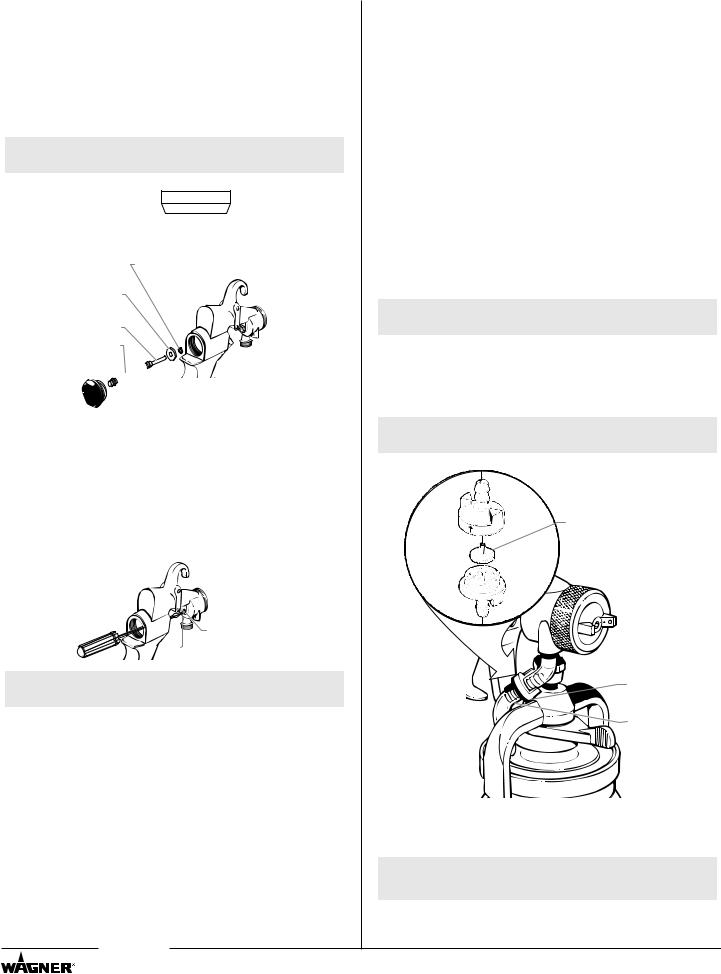
Removing the Packing
1.Remove the packing nut using a 3⁄8 inch wrench.
2.Insert a long, narrow-bladed flathead screwdriver through the back of the gun and into the packing hole.
3.Press the screwdriver firmly into the packing and turn counterclockwise. This should back the old packing out of the threaded hole. If it does not, push the screwdriver more firmly into the packing and try again. If this still does not remove the packing, use a pick tool to pull the packing out.
Packing Hole |

 Packing Nut
NOTE: Make sure all of the old packing is removed before installing the new packing.
Installing the New Packing and Reassembling the Gun
1.Place the new packing into the packing hole.
2.Thread the packing nut one turn into the packing hole. Do not tighten.
3.Push the needle guide shaft through the back of the gun body and thread on the retaining nut.
4.Grasp the material flow adjustment housing with the needle attached. Slide the needle with the spring and the rear
air valve seal through the needle guide shaft and into the packing nut. Tighten the material flow adjustment housing securely using a wrench.
5.Tighten the packing nut securely using a 3/8 inch wrench, then loosen the packing nut a quarter turn.
6.Assemble the trigger by inserting the retaining pin or pins and attaching the snap rings.
7.Pull the trigger to make certain the needle moves freely. If the needle sticks, loosen the packing nut. If the packing leaks, tighten the packing nut.
Replacing the Check Valve, Valve Seal, and Air Tubes
The check valve is a one-way valve designed to allow air into the cup, pressurizing the cup’s contents. Because it is a one-way valve, it prevents paint from seeping up the air tube into the air passages of the gun. It also eliminates any delay in material flow when the gun is triggered by maintaining pressure in the cup.
The check valve rotates open easily for cleaning. It contains a valve seal that can be removed and cleaned with soap and water for waterborne materials or a compatible solvent for other materials. To replace the check valve, the valve seal, and/or the air tubes:
1.Pull the lower air tube from the bottom of the check valve.
2.Pull the check valve from the upper air tube.
3.Unscrew the two halves of the check valve.
4.Remove the worn valve seal.
5.Clean the check valve body with a solvent appropriate to the type of material being used.
Note: Thoroughly clean the inside of the top half of the check valve but do not scratch it.
6.Insert a new valve seal, stem up, into the top of the check valve as shown.
7.Tighten the two halves of the check valve together.
8.Insert the top of the check valve into the upper air tube.
Note: Insert the check valve into the air tube so that the arrow on the valve points toward the gun.
GUN
 Valve Seal


 Air Tube


 Check Valve
Air Tube
9.If the lower air tube is too long, trim the tube so that it fits the gun.
10.Push the lower air tube onto the bottom of the check valve.
Note: Make sure to attach the shorter air tube to the gun fitting and the longer air tube to the cup lid air nipple.
English |
6 |
© Wagner Spray Tech. All rights reserved. |
|
|
|
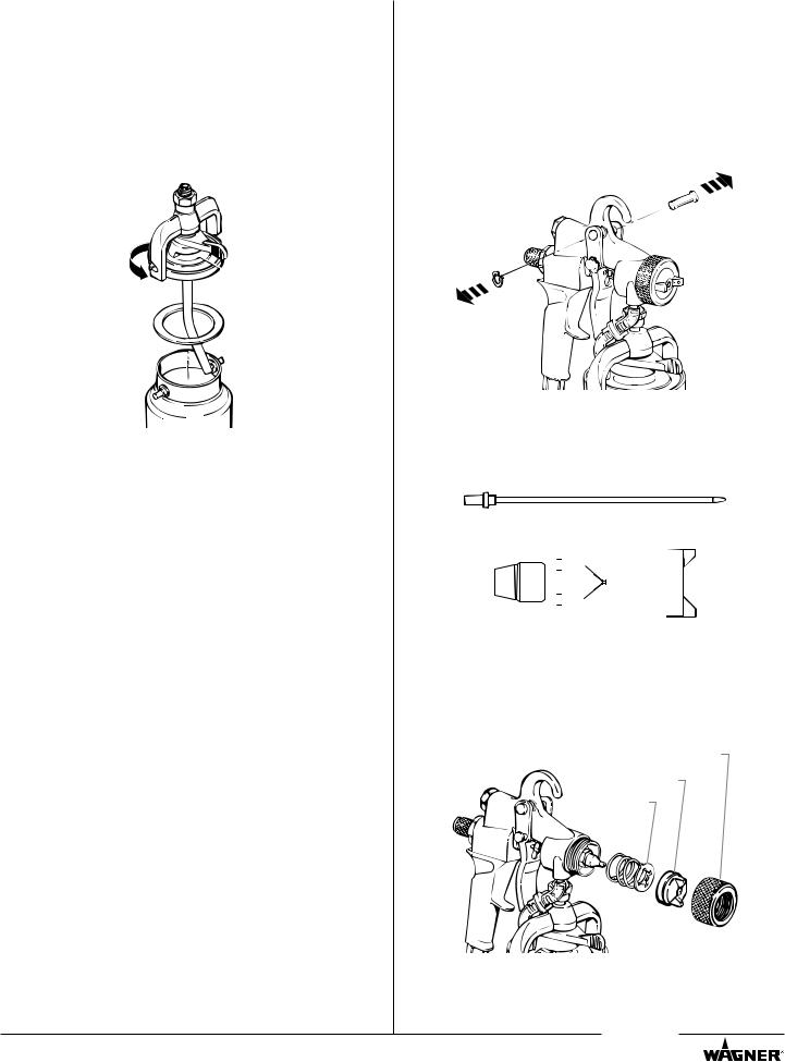
Replacing the Cup Gasket
The cup gasket must be replaced periodically due to normal wear. It is important to inspect the cup gasket during each cleaning.
1.Release the cup locking lever.
2.Hold the cup and twist the spray gun in the direction indicated by the arrows on the bridge.
3.Lift the spray gun away from the cup.
4.Pull the worn cup gasket out of the lid.
5.Press a new cup gasket into the lid.
6.Place the spray gun onto the top of the cup.
Bridge


 Cup Locking
Lever
 Lid
Lid
Cup Gasket
7.Turn the spray gun opposite the direction indicated by the arrows on the bridge until the pegs on the cup are in the notches of the bridge.
8.Tighten the cup locking lever.
Converting to a Single Pin Trigger
The trigger on your HVLP spray gun can be converted to a single pin setup for a softer pull. Trigger pull is reduced by removing the upper trigger pin and operating the gun with only the lower trigger pin in place. This setup reduces finger fatigue and provides greater control when spraying thin, light viscosity materials such as stains, varnishes, and sealers.
1.Remove the retaining clip on the upper trigger pin by placing the flat edge of a screwdriver between the clip and the pin and gently prying it off.
2.Pull the trigger pin out from the opposite side of the gun.
Choosing a Projector Set
Your HVLP spray gun should be fitted with the proper projector set for the type of work you will be performing. A projector set consists of a needle assembly, a fluid nozzle, and an air cap.
Needle Assembly
|
|
|
|
|
|
|
|
|
|
|
|
|
|
|
|
|
|
|
|
|
|
|
|
|
|
|
|
|
|
|
|
|
|
|
|
|
|
|
|
|
|
|
|
|
|
|
|
|
|
|
|
|
|
|
|
|
|
|
|
|
|
|
|
|
Fluid Nozzle |
|
|
|
|
||||||||
|
|
|
|
|||||||||
|
|
Air Cap |
||||||||||
You should choose a projector set based on two things: the type of material to be sprayed and the finish desired.
The chart on page 9 should help you to make the right choice.
Changing a Projector Set
1.Remove the air cap ring, air cap, and spring plate.
Air Cap Ring
Air Cap
Spring Plate
© Wagner Spray Tech. All rights reserved. |
7 |
English |
|
|
|
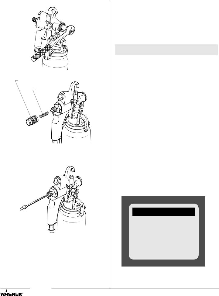
2.Remove the fluid nozzle.
3. Remove the material flow adjustment knob and spring.
Material Flow Adjustment Knob
Spring
4.Remove the needle.
important: If the needle does not slide out easily, loosen the packing nut to prevent the needle or packing from being damaged.
5.Install the new projector set in reverse order.
Optional Accessories
Part Number |
Description |
|
0277090 |
Projector set, low air flow, #2A complete |
|
0277091 |
Projector set, low air flow, #3A complete |
|
0277092 |
Projector set, low air flow, #4A complete |
|
0277093 |
Projector set, low air flow, #5A complete |
|
0277094 |
Projector set, low air flow, #6A complete |
|
0508124 |
Cover, clip-on, 1 quart |
|
0279941 |
Deluxe tip accessory kit |
|
0550962 |
17-Piece gun cleaning kit |
|
0295267 |
Standard Low CFM Kit |
|
Note: The “low air flow” projector sets and air caps are suitable for low CFM compressors.
Repair Kits
Part Number |
Description |
|
|
0297051 |
Check valve repair kit (Includes 3 assemblies) |
||
0276257 |
Check valve membrane kit |
||
|
(includes 10 membranes) |
||
0297052 |
Gasket, cup, white (includes 6 gaskets) |
||
0276258 |
Gasket, cup, Thiokol - black (includes 6 gaskets) |
||
0277943 |
HVLP gun repair kit |
||
|
Includes: |
||
|
• front air valve seal |
||
|
• rear air valve seal |
||
|
• |
needle packing |
|
|
• air control valve o-ring (2) |
||
|
• |
check valve assembly |
|
|
• check valve tube, short |
||
|
• check valve tube, long |
||
|
• |
cup gasket |
|
Questions?
Call Wagner Technical Service at:
1-800-880-0993
Register your product online at:
www.wagnerspraytech.com
Proper registration will serve as proof of purchase in the event your original receipt becomes misplaced or lost.
English |
8 |
© Wagner Spray Tech. All rights reserved. |
|
|
|

Material Reduction/Projector Set Chart
Before spraying, the material being used must be thinned with an appropriate solvent and the proper projector set must be installed. It is always best to follow the material manufacturers recommendations and thinning procedures.
There are two simple methods of measuring the proper thickness of a material:
1.Dip a paint stick into the material and remove it, watching carefully as the material runs off. When the material begins to form drops, the drops should fall about 1 second apart.
2.Use a viscosity cup (P/N 0153165). Dip the cup into the material and remove it. Use a watch or clock to time how long the material drains from the cup in a continuous stream. Once the continuous stream breaks, stop timing and refer to the table below. Add the appropriate solvent and continue testing until the proper thickness is reached for the type of material you are using.
Material |
% of reduction |
Time |
Solvent |
Projector Set |
|
|
|
|
|
Latex |
20-25% |
30-35 sec. |
Water |
5 |
Oil |
10-20% |
20-30 sec. |
Mineral Spirits |
4 |
Epoxy |
1-10% |
30-35 sec. |
Mfg. Recommendations |
5 |
Clear wood finish |
Full strength |
NA |
Mfg. Recommendations |
4 |
Varnish |
Mfg. Recommendations |
NA |
Naphtha |
3 |
Polyurethane |
10% |
18-22 sec. |
M.E.K. |
3 |
Sealer |
Full strength |
NA |
Mineral spirits |
3 |
Oil-based primer |
15-20% |
30-35 |
Mineral spirits |
4 |
Fast-dry enamel |
25% |
20-25 |
Mineral spirits |
4 |
Stain |
Full strength |
NA |
Mfg. Recommendations |
3 |
Metal primer |
15% |
25-30 sec. |
Mineral spirits |
4 |
Industrial enamel |
15% |
30-35 sec. |
Mineral spirits |
4 |
Aluminum paint |
Full strength |
NA |
Mineral spirits |
4 |
Lacquer sealer |
Mfg. Recommendations |
18-22 sec. |
Lacquer thinner |
3 |
Lacquer |
50% |
18-22 sec. |
Lacquer thinner |
3 |
Troubleshooting
Problem |
Cause |
Solution |
||||||||||
A. Little or no paint flow |
1. |
Dried paint blocking fluid nozzle |
1. |
Disassemble and clean |
||||||||
|
|
|
2. |
No air pressure in paint cup or pot |
2. |
Inspect air tube, cup or pot gasket, clean or replace. |
||||||
|
|
|
3. |
Check valve in air tube plugged |
3. |
Clean or replace the check valve assembly |
||||||
|
|
|
4. |
No fluid pressure |
4. |
Check material supply |
||||||
|
|
|
5. |
Blockage in material hose |
5. |
Clean by flushing with solvent |
||||||
|
|
|
|
|
|
|
|
|
|
|
||
B. |
Paint leaking |
1. |
Improper size needle or nozzle |
1. |
Replace |
|||||||
|
|
|
2. |
Damaged needle or nozzle |
2. |
Replace |
||||||
|
|
|
3. |
Loose nozzle |
3. |
Tighten |
||||||
|
|
|
4. |
Loose packing nut |
4. |
Tighten |
||||||
|
|
|
5. |
Needle not closing properly |
5. |
a) Loosen packing nut |
||||||
|
|
|
|
|
|
|
|
b) Replace needle spring |
||||
|
|
|
|
|
|
|
|
c) Remove dried paint from needle |
||||
|
|
|
|
|
|
|
|
|
|
|
||
C. Paint is backing up past the |
1. |
Gun is being tilted too much when it is not |
1. |
Tilt the gun only when spraying |
||||||||
|
check valve |
|
spraying |
|
|
|
|
|
|
|||
|
|
|
2. |
Check valve leaks |
2. |
Clean or replace the check valve |
||||||
|
|
|
|
|
|
|
|
|
|
|
||
D. |
Poor spray pattern |
1. |
Air holes in air cap ears are clogged |
1. |
Remove and clean air holes |
|||||||
|
|
|
2. |
Nozzle is clogged |
2. |
Clean with appropriate solvent |
||||||
|
|
|
3. |
Damaged nozzle or needle |
3. |
Remove and replace |
||||||
|
|
|
|
|
|
|
|
|
|
|
||
E. |
Pulsating spray |
1. |
Loose or damaged packing |
1. |
Tighten or replace |
|||||||
|
|
|
|
|
|
|
|
|
|
|
||
F. Pattern is heavy in the middle |
1. |
Too much fluid pressure |
1. |
Reduce pressure |
||||||||
|
|
|
|
|
|
|
|
|
|
|
||
G. |
Gun spitting paint |
1. |
Valve in air tube is not operating properly |
1. |
Replace valve assembly |
|||||||
|
|
|
2. |
Material too thick |
2. |
Thin material |
||||||
|
|
|
3. |
Projector set is too small. |
3. |
Install the proper projector set. |
||||||
|
|
|
|
|
|
|
|
|
|
|
||
H. Paint build up on the air cap |
1. |
Improper adjustment of cap |
1. |
Adjust the air cap properly so that paint flows freely |
||||||||
|
|
|
|
|
|
|
|
through the cap |
||||
|
|
|
|
|
|
|
|
|
|
|
||
I. |
Too much overspray |
1. |
Air pressure too high |
1. |
Reduce air pressure |
|||||||
|
|
|
2. |
Material too thin |
2. |
Add unthinned paint |
||||||
|
|
|
3. |
Spray gun too far from surface |
3. |
Move closer |
||||||
|
|
|
|
|
|
|
|
|
|
|
|
|
© Wagner Spray Tech. All rights reserved. |
|
9 |
|
|
|
|
English |
|
|
|||
|
|
|
|
|
|
|
|
|
|
|
|
|
 Loading...