


Translation of the Original
Operating Manual
Version 05/2015
Electrostatic AirCoat Spray Gun
for manual operation
for flat or round jet nozzles
B_03154

EDITION 05/2015 |
ORDER NUMBER DOC2319150 |
|
OPERATING MANUAL
Table of Contents
1 |
ABOUT THESE INSTRUCTIONS |
6 |
1.1 |
Preface |
6 |
1.2 |
Warnings, Notices and Symbols in these Instructions |
6 |
1.3 |
Languages |
7 |
1.4 |
Abbreviations |
7 |
1.5 |
Terminology for the Purpose of this Manual |
8 |
2 |
CORRECT USE |
9 |
2.1 |
Device Type |
9 |
2.2 |
Type of Use |
9 |
2.3 |
Use in an Explosion Hazard Area |
9 |
2.4 |
Safety Parameters |
9 |
2.5 |
Processible Working Materials |
10 |
2.6 |
Reasonably Foreseeable Misuse |
11 |
2.7 |
Residual Risks |
11 |
3 |
IDENTIFICATION |
12 |
3.1 |
CE Explosion Protection Identification |
12 |
3.2 |
Identification "X" |
12 |
3.3 |
Type Plate |
13 |
4 |
GENERAL SAFETY INSTRUCTIONS |
14 |
4.1 |
Safety Instructions for the Operator |
14 |
4.1.1 |
Electrical Equipment |
14 |
4.1.2 |
Personnel Qualifications |
14 |
4.1.3 |
Safe Work Environment |
14 |
4.2 |
Safety Instructions for Staff |
15 |
4.2.1 |
Safe Handling of WAGNER Spray Devices |
15 |
4.2.2 |
Grounding the Device |
16 |
4.2.3 |
Product Hoses |
16 |
4.2.4 |
Cleaning and Flushing |
17 |
4.2.5 |
Handling Hazardous Liquids, Varnishes and Paints |
18 |
4.2.6 |
Touching Hot Surfaces |
18 |
4.3 |
Protective and Monitoring Equipment |
18 |
4.4 |
Use in Areas Subject to Explosion Hazards |
19 |
4.4.1 |
Safety Regulations |
19 |
4.5 |
Safety-Relevant Information about Discharges |
19 |
5 |
DESCRIPTION |
20 |
5.1 |
Structure (Standard Variant) |
20 |
5.1.1 |
Securing the Spray Gun Against Actuation |
21 |
5.2 |
Mode of Operation |
21 |
5.3 |
Protective and Monitoring Equipment |
23 |
5.4 |
Scope of Delivery |
23 |
5.5 |
Technical Data |
24 |
5.6 |
Spraying Procedure |
25 |
5.6.1 |
Spraying Procedure for AirCoat Round Spray |
25 |
5.6.2 |
Spraying Procedure for AirCoat Fan Spray |
25 |
5.6.3 |
Electrostatic Effect |
26 |
3

EDITION 05/2015 |
ORDER NUMBER DOC2319150 |
|
OPERATING MANUAL
Table of Contents
6 |
ASSEMBLY AND COMMISSIONING |
27 |
6.1 |
Training Assembly/Commissioning Staff |
27 |
6.2 |
Storage Conditions |
27 |
6.3 |
Installation Conditions |
27 |
6.4 |
Assembly and Installation |
27 |
6.4.1 |
Typical Electrostatic Spraying System |
28 |
6.4.2 |
Ventilation of the Spray Booth |
29 |
6.4.3 |
Air Supply |
31 |
6.4.4 |
Product Supply |
31 |
6.4.5 |
Grounding |
32 |
6.5 |
Preparation of Lacquer |
34 |
6.5.1 |
Viscosity Conversion Table |
34 |
6.6 |
Commissioning |
35 |
6.6.1 |
Safety Instructions |
35 |
6.6.2 |
Preparation for Commissioning |
35 |
6.6.3 |
Commissioning |
35 |
6.6.3.1 |
Gun Cables and Gun Cable Extensions |
36 |
6.6.4 |
Verifying a Safe Operational Condition |
37 |
7 |
OPERATION |
38 |
7.1 |
Training the Operating Staff |
38 |
7.2 |
Safety Instructions |
38 |
7.2.1 |
Emergency Deactivation |
39 |
7.2.2 |
General Rules for Making Adjustments to the Spray Gun |
39 |
7.3 |
Work |
40 |
7.3.1 |
Filling with Working Material |
41 |
7.3.2 |
Checking the Spray Pattern (Without Electrostatics) |
41 |
7.3.3 |
Spraying |
43 |
7.3.4 |
Pressure Relief / Work Interruption |
44 |
7.3.5 |
Flushing Out Clogged Round Jet Nozzles |
45 |
7.3.6 |
Replacing Round Jet Nozzle's Nozzle Insert |
45 |
7.3.7 |
Changing from AirCoat Round Jet to AirCoat Flat Jet |
46 |
7.3.8 |
Replacing the AirCoat Flat Jet Nozzles |
48 |
7.3.9 |
Cleaning of the Nozzle Parts |
49 |
7.3.10 |
Eliminate Nozzle Clogging |
50 |
7.3.11 |
Changing the Valve Housing |
52 |
8 |
CLEANING AND MAINTENANCE |
54 |
8.1 |
Cleaning |
54 |
8.1.1 |
Cleaning Staff |
54 |
8.1.2 |
Safety Instructions |
54 |
8.1.3 |
Cleaning and Flushing the Device |
56 |
8.2 |
Maintenance |
58 |
8.2.1 |
Maintenance Staff |
58 |
8.2.2 |
Safety Instructions |
58 |
8.2.3 |
Safety Checks |
59 |
8.2.4 |
Product Hoses, Tubes and Couplings |
60 |
4

EDITION 05/2015 |
ORDER NUMBER DOC2319150 |
|
OPERATING MANUAL
Table of Contents
9 |
TROUBLESHOOTING AND RECTIFICATION |
61 |
10 |
REPAIR WORK |
63 |
10.1 |
Repair Staff |
63 |
10.2 |
Safety Instructions |
63 |
10.3 |
Spray Gun |
64 |
10.3.1 |
Tools |
64 |
10.3.2 |
Disassembly of the Spray Gun |
65 |
10.3.3 |
Cleaning the Parts After Disassembly |
69 |
10.3.4 |
Assembling the Spray Gun |
70 |
11 |
FUNCTIONAL CHECK AFTER REPAIR |
76 |
11.1 |
Checking the High-voltage |
76 |
11.2 |
Air Test |
78 |
11.3 |
Product Pressure Test |
78 |
11.4 |
Test of Spray Pattern |
78 |
12 |
DISPOSAL |
79 |
13 |
ACCESSORIES |
80 |
13.1 |
Round Spray Nozzles |
80 |
13.1.1 |
ACR 5000 Round Jet Nozzle Cap |
80 |
13.1.2 |
AirCoat Round Jet Nozzle Inserts |
80 |
13.2 |
Flat Jet Nozzles |
80 |
13.2.1 |
ACF 5000 Air Caps (Flat Jet) |
80 |
13.2.2 |
ACF5000 AirCoat Flat Jet Nozzles |
81 |
13.3 |
Filter |
83 |
13.4 |
Hoses and Electric Cables |
84 |
13.4.1 |
Standard Hose Sets and Components |
84 |
13.4.2 |
Hose Sets for Low-resistance Products |
86 |
13.4.3 |
Product Hose 1.5 mm |
88 |
13.4.4 |
Gun Cables and Gun Cable Extensions |
88 |
13.5 |
Miscellaneous |
89 |
14 |
SPARE PARTS |
91 |
14.1 |
How Can Spare Parts Be Ordered? |
91 |
14.2 |
GM 5000EAC Spray Gun |
92 |
14.2.1 |
GM 5000EAC Adapter |
94 |
14.2.2 |
GM 5000EAC Handle |
96 |
14.3 |
Accessories Spare Parts Lists |
98 |
14.3.1 |
Fan Spray Nozzles |
98 |
14.3.2 |
ACR 5000 Round Jet Nozzle Cap |
99 |
15 |
WARRANTY AND CONFORMITY DECLARATIONS |
100 |
15.1 |
Important Notes Regarding Product Liability |
100 |
15.2 |
Warranty Claim |
100 |
15.3 |
CE Declaration of Conformity |
101 |
15.4 |
EC Type Examination Certificate |
102 |
15.5 |
Notes on German Regulations and Guidelines |
105 |
5
EDITION 05/2015 |
ORDER NUMBER DOC2319150 |
|
OPERATING MANUAL
1 ABOUT THESE INSTRUCTIONS
1.1 PREFACE
The operating manual contains information about safely operating, maintaining, cleaning and repairing the device.
The operating manual is part of the device and must be available to operating and service staff.
The device may only be operated by trained staff and in compliance with this operating manual. Operating and service personnel should be instructed according to the safety instructions.
This equipment can be dangerous if it is not operated according to the instructions in this operating manual.
1.2 WARNINGS, NOTICES AND SYMBOLS IN THESE INSTRUCTIONS
Warning instructions in this operating manual highlight particular dangers to users and to the device and state measures for avoiding the hazard. These warning instructions fall into the following categories:
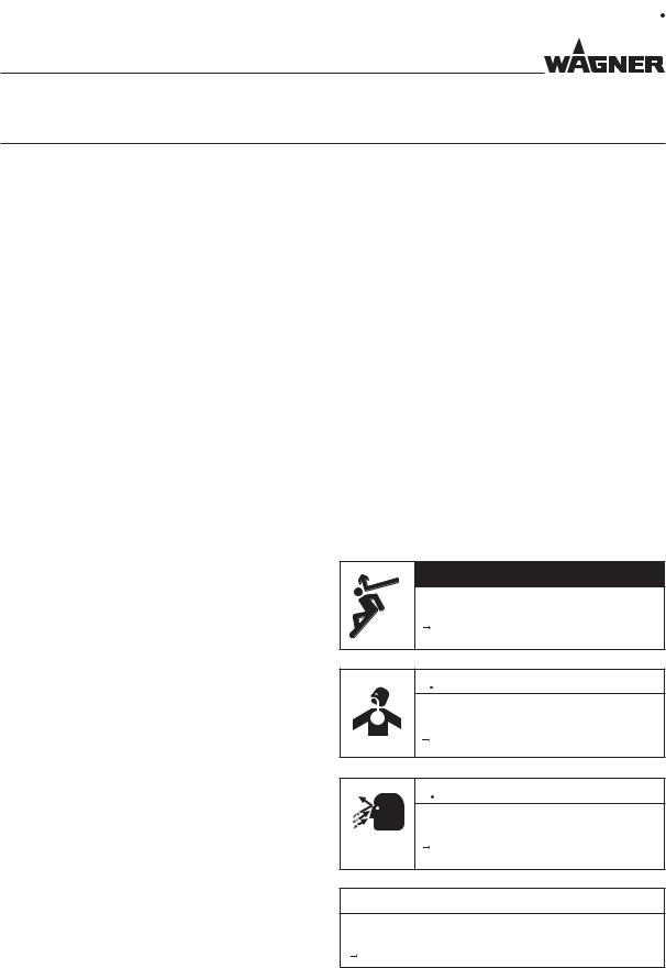
Danger - immediate risk of danger. Non-observance will result in death or serious injury.
Warning - possible imminent danger. Non-observance may result in death or serious injury.
Caution - a possibly hazardous situation. Non-observance may result in minor injury.
Notice - a possibly hazardous situation. Non-observance may result in damage to property.
 DANGER
This notice warns you of a hazard!
Possible consequences of not observing the warning instructions. The signal word indicates the hazard level.
The measures for preventing the danger and its consequences.
 WARNING
This notice warns you of a hazard!
Possible consequences of not observing the warning instructions. The signal word indicates the hazard level.
The measures for preventing the danger and its consequences.
 CAUTION
This notice warns you of a hazard!
Possible consequences of not observing the warning instructions. The signal word indicates the hazard level.
The measures for preventing the danger and its consequences.
NOTICE
This notice warns you of a hazard!
Possible consequences of not observing the warning instructions. The signal word indicates the hazard level.
The measures for preventing the danger and its consequences.
Note - provides information about particular characteristics and how to proceed.
6
EDITION 05/2015 |
ORDER NUMBER DOC2319150 |
|
OPERATING MANUAL
1.3 LANGUAGES
The GM 5000EAC operating manual is available in the following languages:
Language |
Order No. |
|
Language |
Order No. |
|
|
|
|
|
German |
2310481 |
|
English |
2319150 |
French |
2320152 |
|
Italian |
2320153 |
Spanish |
2320154 |
|
Dutch |
2358832 |
Danish |
2359979 |
|
Swedish |
2360027 |
Additional languages on request or at:
1.4 ABBREVIATIONS
Order No. |
Order number |
|
Spare part |
|
Marking in the spare parts lists |
|
AirCoat |
|
Electrostatic AirCoat |
|
Manual gun (gun, manual) |
|
Low-resistance |
|
Stainless steel |
|
Position |
|
Number of pieces |
|
Wrench size |
7

EDITION 05/2015 |
ORDER NUMBER DOC2319150 |
|
OPERATING MANUAL
1.5 TERMINOLOGY FOR THE PURPOSE OF THIS MANUAL
Cleaning |
Manual cleaning of devices and device parts with cleaning agent |
Flushing |
Internal flushing of paint-wetted parts with flushing agent |
Staff qualifications |
|
Trained person |
Is instructed in the tasks assigned to him/her, the potential risks |
|
associated with improper behavior as well as the necessary |
|
protective devices and measures. |
Electrically trained |
Is instructed by an electrician about the tasks assigned to him/ |
person |
her, the potential risks associated with improper behavior as |
|
well as the necessary protective devices and measures. |
Electrician |
Can assess the work assigned to him/her and detect possible |
|
hazards based on his/her technical training, knowledge and |
|
experience in relevant provisions. |
Skilled person |
A person who, based on his/her technical training, experience |
in the context of BGI 764 |
and recent vocational experience, has sufficient technical |
|
knowledge in the area of electrostatic coating and is familiar |
|
with the relevant and generally accepted rules of technology |
|
so that he/she can inspect and assess the status of devices and |
|
coating systems based on workplace safety. |
|
Additional requirements for skilled persons can also be |
|
referred to in TRBS 1203 (2010): Expert knowledge in the areas |
|
of protection against excessive pressure, electrical hazards, and |
|
explosion protection (where applicable). |
|
|
8

EDITION 05/2015 |
ORDER NUMBER DOC2319150 |
|
OPERATING MANUAL
2 CORRECT USE
2.1 DEVICE TYPE
Electrostatic manual spray gun for manual coating of grounded work pieces.
2.2 TYPE OF USE
The GM 5000EAC electrostatic manual spray gun is suitable for spraying liquid products, particularly coating products, using the AirCoat method. Coating products containing solvents of explosion class II A may be used.
WAGNER forbids any other use!
2.3 USE IN AN EXPLOSION HAZARD AREA
The GM 5000EAC electrostatic manual spray gun is suitable for coating electrically conductive objects with liquid coating products and can be used in potentially explosive areas. (See Chapter 3. "Explosion Protection Identification".)
2.4 SAFETY PARAMETERS
WAGNER accepts no liability for any damage arising from incorrect use.
 Use the device only to work with the products recommended by WAGNER.
 Only operate the device as a whole.
 Do not deactivate safety fixtures.
 Use only WAGNER original spare parts and accessories.
The device may only be operated under the following conditions:
 The operating staff must be trained on the basis of this operating manual.
 The safety regulations listed in this operating manual must be observed.
 The operating, maintenance and repair information in this operating manual must be observed.
 The statutory requirements and accident prevention regulation standards in the country of use must be observed.
The electrostatic manual spray gun may only be operated if all parameters are set and all measurements/safety checks are carried out correctly.
9
EDITION 05/2015 |
ORDER NUMBER DOC2319150 |
|
OPERATING MANUAL
2.5 PROCESSIBLE WORKING MATERIALS
Lacquers containing solvents of explosion class II A can be processed with the GM 5000EAC spray gun.
The spray gun basic version is suitable for processing sprayed substances with an electrical resistance of > 150 kΩ (according to the WAGNER scale).
Equipped with a special product hose for low-resistance sprayed substances (available as an accessory), you can also successfully process sprayed substances with an electrical resistance > 50 kΩ (according to the WAGNER scale).
The application effectiveness is always dependant on the composition of the product being used, e.g., pigments or resin.
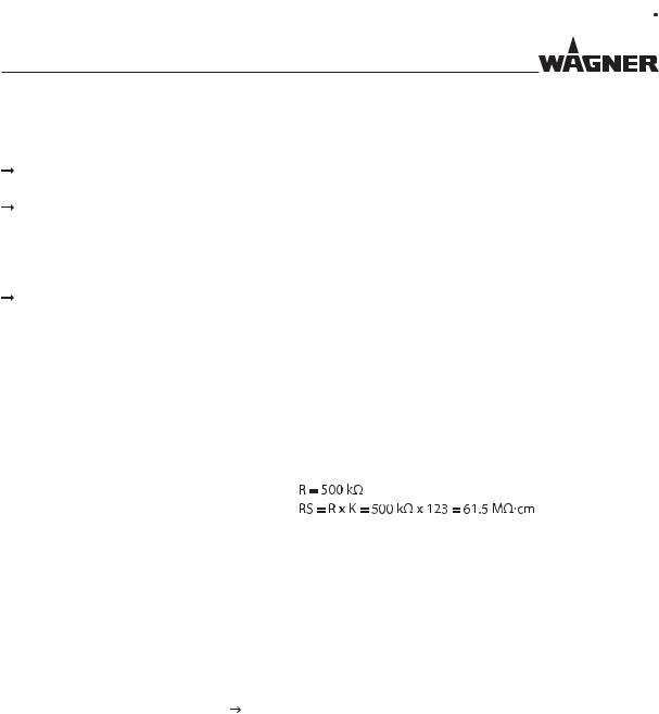
Conversion of Paint Resistance
There are paint resistance measuring devices available on the market that do not directly measure the specific paint resistance.
Multiplying the result of the measurement with the device-specific cell constant (K), we obtain the specific resistance value of the product.
Example:
With WAGNER's paint resistance measuring device the cell constant is K =123.
Measured value according to the WAGNER scale
Specific resistance (RS)
Note:
Using sprayed substances with too low an electrical resistance, the application of electrostatics does not show any effect, i.e. there is no "paint wrap around" on the object to be sprayed.
The suitability of the spray product with regard to the charging ability can be read from the actual values for high-voltage (kV) and for the spray current (μA) shown in the illuminated displays either on the VM 5000 control unit or on the spray gun.
High kV value, low μA value |
= ok |
Low kV value, high μA value |
= excessive conductivity of the paint |
|
No wrap-around |
 Please contact your localWAGNER dealer and the lacquer manufacturer if you encounter application problems.
10
EDITION 05/2015 |
ORDER NUMBER DOC2319150 |
|
OPERATING MANUAL
2.6 REASONABLY FORESEEABLE MISUSE
The forms of misuse listed below may result in physical injury or property damage:
use with non-authorized control units; coating work pieces which are not grounded;
working with an ungrounded lacquer supply system;
performing unauthorized conversions or modifications to the device; processing inadmissible coating products;
processing dry or similar coating products, e.g., powder;
using defective components, spare parts or accessories other than those described in the "Accessories" chapter of this operating manual;
continuing work with a defective or kinked product hose; working with incorrectly set values;
processing food.
2.7 RESIDUAL RISKS
Residual risks are risks which cannot be ruled out even in the event of correct use.
If necessary, warning and prohibition signs at the relevant points of risk indicate residual risks.
Residual risk |
Source |
Consequences |
Specific measures |
Lifecycle phase |
Skin contact with |
Handling of |
Skin irritations, |
Wear protective |
Operation, |
lacquers and |
lacquers and |
allergies |
clothing |
maintenance, |
cleaning agents |
cleaning agents |
|
Observe safety data |
disassembly |
|
|
|
sheets |
|
|
|
|
|
|
Lacquer in air |
Lacquering outside |
Inhalation of |
Observe work and |
Operation, |
outside the defined |
the defined working |
substances |
operation instructions |
maintenance |
working area |
area |
hazardous to health |
|
|
|
|
|
|
|
11
EDITION 05/2015 |
ORDER NUMBER DOC2319150 |
|
OPERATING MANUAL
3 IDENTIFICATION
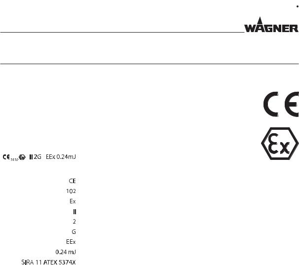
3.1 CE EXPLOSION PROTECTION IDENTIFICATION
As defined in the Directive 94/9/EC (ATEX), the device is suitable for use in potentially explosive areas.
Device type: |
GM 5000EAC electrostatic manual spray gun |
Manufacturer: |
J. Wagner AG |
|
CH-9450 Altstätten, Switzerland |
|
|
SIRA 11 ATEX5374X |
|
|
European Communities |
|
Notified body: PTB |
|
Explosion-proof equipment |
|
Device class II (not mining) |
|
Category 2 device (suitable for zone 1) |
|
Ex-atmosphere gas |
|
Explosion protection for electrical devices |
|
Maximum ignition energy |
|
Number of type examination certificate |
|
"X": see chapter 3.2 |
Temperature notes
-Maximum surface temperature: 85 °C; 185 °F
-Maximum permissible product temperature: 50 °C; 122 °F
-Permissible ambient temperature: 0 to +40 °C; +32 to +104 °F
3.2 IDENTIFICATION "X"
Note:
The EC Type Examination Certificate from SIRA can be found in Chapter 15.4.
This certification covers the following:
-use of the spray gun in Zone 1;
-use of the VM 5000 or VM 500 control unit as related equipment for the spray gun.
The control unit may be used in zone 2. This usage is certified by the manufacturer (see operating manual of the control unit).
12
EDITION 05/2015 |
ORDER NUMBER DOC2319150 |
|
OPERATING MANUAL
Cable connections
Only cable assigned to the device may be used (see Chapter 13).
Permissible Device Combinations
The GM 5000EAC manual spray gun may only be connected to the control units listed below:
-VM 500 control unit
-VM 5000 control unit
 WARNING
Incorrect use!
Risk of injury and damage to the device.
 Connect the GM 5000EAC manual spray gun only to original
WAGNER control units.
3.3 TYPE PLATE
J. Wagner AG
CH-9450 Altstätten
GM 5000EAC
Art. Nr.: |
2309823 |
high voltage: |
max. 80kV DC |
current: |
max. 100μA DC |
max. mat. pressure: 25MPa; 250bar; 3626psi max. air pressure: 0.8MPa, 8bar; 116psi
1Warning: Danger of becoming injured by high-pressure jet
2 Device type
3 Article number
4 Maximum high-voltage
5 Maximum current
6 Maximum product pressure
7 Maximum air pressure
8Do not dispose of used electrical equipment with household refuse
9 Identification and test centre
10 
B_04366
|
8 |
0102 II 2 G |
9 |
EEx 0.24 mJ |
SIRA 11 ATEX 5374X
For Electro. Fin. Appl. CL. I, GP. D, Spray Matl. 10
Serial number
The serial number (S) on the underside of the handle.
S |
B_03558 |
13
EDITION 05/2015 |
ORDER NUMBER DOC2319150 |
|
OPERATING MANUAL
4 GENERAL SAFETY INSTRUCTIONS
4.1 SAFETY INSTRUCTIONS FOR THE OPERATOR
 Keep this operating manual at hand near the device at all times.
 Always follow local regulations concerning occupational safety and accident prevention.
4.1.1ELECTRICAL EQUIPMENT
Electrical devices and equipment
 To be provided in accordance with the local safety requirements with regard to the operating mode and ambient influences.
 May only be maintained by skilled electricians or under their supervision. With open housings, there is a danger from line voltage.
 Must be operated in accordance with the safety regulations and electrotechnical regulations.
 Must be repaired immediately in the event of problems.
 Must be decommissioned if they pose a hazard or are damaged.
 Must be de-energized before work is commenced on active parts. Inform staff about planned work. Observe electrical safety regulations.
 Connect all devices to a common grounding point.
 Only operate the device with a properly installed socket with a protective ground wire connection.
 Keep liquids away from electrical devices.
4.1.2PERSONNEL QUALIFICATIONS
 Ensure that the device is only operated, maintained and repaired by trained persons.
4.1.3SAFE WORK ENVIRONMENT
 Ensure that the floor in the working area is static dissipative in accordance with EN 61340-4-1 (resistance must not exceed 100 megohms).
 Ensure that all persons within the working area wear static dissipative shoes. Footwear must comply with EN 20344. The measured insulation resistance must not exceed 100 megohms.
 Ensure that during spraying, persons wear static dissipative gloves. Grounding takes place via the spray gun handle.
 If protective clothing is worn, including gloves, it has to comply with EN 1149-5. The measured insulation resistance must not exceed 100 megohms.
 Paint mist extraction systems/ventilation systems must be fitted on site according to local regulations.
 Ensure that the following components of a safe working environment are available: - Product/air hoses adapted to the working pressure.
- Personal safety equipment (breathing and skin protection).
14

EDITION 05/2015 |
ORDER NUMBER DOC2319150 |
|
OPERATING MANUAL
 Ensure that there are no ignition sources such as naked flames, sparks, glowing wires, or hot surfaces in the vicinity. Do not smoke.
 Ensure that the pipe joints, hoses, equipment parts and connections are permanently, technically leak-proof:
-Periodic preventative maintenance and service (replacing hoses, checking tightness strength and connections etc.).
-Regular monitoring of leaks and defects via visual inspection and odor testing, e.g., daily before commissioning, at the end of work or weekly.
 In the event of defects, immediately bring the device or system to a stop and arrange to have repairs carried out immediately.
4.2 SAFETY INSTRUCTIONS FOR STAFF
 Always follow the information in this manual, particularly the general safety instructions and the warning instructions.
 Always follow local regulations concerning occupational safety and accident prevention.
  Anyone fitted with a pacemaker must not enter the high-voltage area!
4.2.1SAFE HANDLING OF WAGNER SPRAY DEVICES
The spray jet is under pressure and can cause dangerous injuries. Avoid injection of paint or flushing agents:
 Never point the spray gun at people.
 Never reach into the spray jet.
 Before all work on the device, in the event of work interruptions and functional faults: - Switch off the energy/compressed air supply.
- Relieve the pressure from the spray gun and device. - Secure the spray gun against actuation.
- In the event of functional faults, remedy the fault as described in the "Troubleshooting" chapter.
 If necessary or at least every 12 months, the liquid ejection devices should be checked for safe working conditions by an expert (e.g., WAGNER Service Technician) in accordance with the guidelines for liquid ejection devices (ZH 1/406 and BGR 500 Part 2 Chapter 2.29 and 2.36).
- For shut down devices, the examination can be suspended until the next start-up.  Carry out the work steps as described in the "Pressure Relief" chapter:
-if pressure relief is required.
-If the spraying work is interrupted or stopped.
-Before the device is cleaned on the outside, checked or serviced.
-Before the spray nozzle is installed or cleaned.
In the event of skin injuries caused by paint or flushing agents:
 Note the paint or flushing agent that you have been using.
 Consult a doctor immediately.
Avoid risk of injury from recoil forces:
 Ensure that you have firm footing when operating the spray gun.
 Only hold the spray gun briefly in a position.
15

EDITION 05/2015 |
ORDER NUMBER DOC2319150 |
|
OPERATING MANUAL
4.2.2GROUNDING THE DEVICE
Friction, flowing liquids and air or electrostatic coating processes create charges. Flames or sparks can form during discharge. Grounding prevents electrostatic charging.
 Ensure that the device is grounded.
 See chapter "Grounding".
 Ground the work pieces to be coated.
 Ensure that all persons inside the working area are grounded, e.g., that they are wearing static dissipative shoes.
 Wear static dissipative gloves when spraying. The grounding takes place via the spray gun handle.
 The spray substance supply (spray substance tank, pump, etc.) must be grounded.
4.2.3PRODUCT HOSES
 Ensure that the hose material is chemically resistant to the sprayed products and the flushing agents used.
 Ensure that the product hose is suitable for the pressure generated.
 Ensure that the following information can be seen on the high-pressure hose: - Manufacturer
- Permissible operating pressure - Date of manufacture
 Make sure that the hoses are laid only in suitable places. Hoses should not be laid in the following places under any circumstances:
-in high-traffic areas,
-at sharp edges,
-on moving parts or
-on hot surfaces.
 Ensure that the hoses are never run over by vehicles (e.g., fork lifts), or that the hoses are never put under pressure from the outside in any other way.
 Ensure that the hoses are never kinked. Observe maximum bending radii.
  Make sure that the hoses are never used to pull or move the equipment.
  Suction hoses may not be subjected to pressure.
Several liquids have a high expansion coefficient. In some cases their volume can rise with consequent damage to pipes, fittings, etc. and cause fluid leakage.
When the pump sucks liquid from a closed tank, ensure that air or a suitable gas can enter the tank. Thus a negative pressure is avoided. The vacuum could implode the tank (squeeze) and can cause it to break. The tank would leak and the liquid would flow out.
The pressure created by the pump is a multiplication of the inlet air pressure.
16
EDITION 05/2015 |
ORDER NUMBER DOC2319150 |
|
OPERATING MANUAL
4.2.4CLEANING AND FLUSHING
 Relieve the pressure from the device.
 De-energize the device electrically.
 Preference should be given to non-flammable cleaning and flushing agents.
 Observe the specifications of the paint manufacturer.
 Ensure that the flash point of the cleaning agent is at least 15 K above the ambient temperature or that cleaning is undertaken at a cleaning station with technical ventilation.
 Take measures for workplace safety (see Chapter 4.1.3).
 When commissioning or emptying the device, please note that an explosive mixture may temporarily exist inside the lines and components of equipment:
-depending on the coating product used,
-depending on the flushing agent (solvent) used, explosive mixture inside the lines and items of equipment.
 Only electrically conductive tanks may be used for cleaning and flushing agents.
  The tanks must be grounded.
An explosive gas/air mixture forms in closed tanks.
 Never spray into a closed tank when using solvents for flushing.
External cleaning
When cleaning the exterior of the device or its parts, also observe the following:  Disconnect the pneumatic supply line.
 Use only moistened cloths and brushes. Never use abrasive agents or hard objects and never spray cleaning agents with a gun. Cleaning the device must not damage it in any way.
 Ensure that no electrical component is cleaned with nor even immersed into solvent.
  Which cleaning agent is used to clean the spray gun depends on which parts of the spray gun have to be cleaned and which product has to be removed. When cleaning the spray gun, only use non-polar cleaning agents to prevent conductive residues on the surface of the spray gun. Should it however, be necessary to use a polar cleaning agent, all residues of this cleaning agent have to be removed by using a non-conductive and non-polar cleaning agent, once the cleaning is finished.
17

EDITION 05/2015 |
ORDER NUMBER DOC2319150 |
|
OPERATING MANUAL
4.2.5HANDLING HAZARDOUS LIQUIDS, VARNISHES AND PAINTS
 When preparing or working with lacquer and when cleaning the device, follow the working instructions of the manufacturer of the lacquers, solvents and cleaning agents being used.
 Take the specified protective measures, in particular wear safety goggles, protective clothing and gloves, as well as skin protection cream if necessary.
 Use a mask or breathing apparatus if necessary.
 For sufficient health and environmental safety: Operate the device in a spray booth or on a spraying wall with the ventilation (extraction) switched on.
 Wear suitable protective clothing when working with hot products.
4.2.6TOUCHING HOT SURFACES
 Only touch hot surfaces if you are wearing protective gloves.
 When operating the device with a coating product with a temperature of > 43 °C; 109.4 °F: - Identify the device with a warning label "Warning – hot surface".
Order No. |
|
9998910 |
Instruction label |
9998911 |
Protection label |
Note: Order the two stickers together.
4.3 PROTECTIVE AND MONITORING EQUIPMENT
 Protective and monitoring equipment must not be removed, modified or rendered unusable.
 Regularly check for perfect functioning.
 If defects are detected on protective and monitoring equipment, the system must not be operated until these defects are remedied.
18
EDITION 05/2015 |
ORDER NUMBER DOC2319150 |
|
OPERATING MANUAL
4.4 USE IN AREAS SUBJECT TO EXPLOSION HAZARDS
The spray gun may be used in potentially explosive areas. The following safety regulations must be observed and followed.
4.4.1SAFETY REGULATIONS
 Observe safety instructions in Chapter 3.2.
Safe handling of WAGNER spray devices
Mechanical sparks can form if the device comes into contact with metal.
In an explosive atmosphere:
 Do not knock or push the device against steel or rusty iron.
 Do not drop the spray gun.
 Use only tools that are made of a permitted material.
Ignition temperature of the coating product
 Ensure that the ignition temperature of the coating product is above the maximum surface temperature.
Surface spraying, electrostatics
 Never spray device parts using electrostatic equipment (electrostatic spray gun!).
Medium supporting atomizing
 To atomize the product, use only weakly oxidizing gases, e.g., air.
Cleaning
If there are deposits on the surfaces, the device may form electrostatic charges. Flames or sparks can form during discharge.
 Remove deposits from the surfaces to maintain conductivity.
  Use only a damp cloth to clean the device.
4.5 SAFETY-RELEVANT INFORMATION ABOUT DISCHARGES
The plastic parts of the spray gun are charged electrostatically by the high-voltage field of the spray gun. Contact with plastic parts harmless discharges (brush discharges) may occur. They are completely non-hazardous for human health.
When keeping a distance of 4 to 10 mm; 0.15 to 0.4 inch between spray gun and object to be sprayed, the corona discharge at the end of the electrode is visible in the dark.
19

EDITION 05/2015 |
ORDER NUMBER DOC2319150 |
|
OPERATING MANUAL
5 DESCRIPTION
5.1 STRUCTURE (STANDARD VARIANT)
Note:
The nozzle parts (pos. 6; 7; 13 and 14) do not belong to the basic equipment of the spray gun. The different versions can be found in Chapter 13 "Accessories".
|
|
|
|
|
9 |
|
1 |
|
|
|
|
|
|
|
|
|
8 |
|
2 |
3 |
|
|
22 |
|
|
4 |
|
||
|
|
|
|
||
|
|
15 |
6 |
7 |
|
21 |
|
16 |
|
10 |
|
|
|
|
|||
|
|
|
|
||
|
|
5 |
|
|
11 |
|
20 |
|
17 |
|
18 |
|
19 |
Pos |
Description |
1 |
Suspension hook |
2 |
Display (spray current and recipe) |
3 |
Display standby |
4 |
Operating button (standby and recipe change) |
5 |
Protection against contact with union nut |
6 |
Air cap for flat jet nozzle |
|
(see accessories in Chapter 13.2.1) |
7 |
ACF 5000 flat jet nozzle |
|
(see accessories in Chapter 13.2.2) |
8 |
Adapter |
9 |
Cover |
10 |
Handle |
11 |
Trigger lock |
12 |
Trigger lever |
|
|
|
|
12 |
|
|
|
|
|
|
|
|
||
|
|
13 |
||
14 |
|
|
B_03156 |
|
|
|
|
||
|
|
|||
Pos |
Description |
|||
13 |
Round jet nozzle adapter |
|||
|
|
(see accessories in Chapter 13.1.1) |
||
14 |
Round jet nozzle insert |
|||
|
|
(see accessories in Chapter 13.1.2) |
||
15 |
Sealing plug |
|||
16 |
Air regulation |
|||
17 |
Electric cable connection |
|||
18 |
Atomizing air connection |
|||
19 |
Product connection |
|||
20 |
Filter housing with filter |
|||
21 |
Type plate left |
|||
22 |
Type plate right |
|||
S |
B_03558 |
Note:
The gun type (T) is specified on the type plate and the serial number (S) is specified on the underside of the handle.
20
EDITION 05/2015 |
ORDER NUMBER DOC2319150 |
|
OPERATING MANUAL
5.1.1SECURING THE SPRAY GUN AGAINST ACTUATION
Secure the spray gun against actuation:
 Use the trigger lock (11) to engage the trigger (12).
Note: To secure the entire spraying system, pressure must be relieved as described in Chapter 7.3.4.
5.2 MODE OF OPERATION
When the spray gun is connected to the control unit and the control unit is switched on, the pre-defined recipe (R1, R2 or R3) is shown on the gun display (2) as follows.
Recipe 1 

Recipe 2 

Recipe 3 

2
Recipe change R1  R2
R2  R3
R3  R1
R1
Press the operating button (4) and hold the button pressed for at least 2 seconds to go forward 1 recipe.
3
4
B_03182
Display (2) 
 = Recipe values changed temporarily:
If the operating key (4) is pressed for 2 seconds, the saved recipe values for the previously selected recipes numbers will be reloaded from the memory.
During spraying mode (trigger lever pressed), the status is shown in the display (2) by LEDs.
LED display |
Description |
|
|
LEDs 1 - 3 light up green. |
The spray gun is working in an optimal |
|
high-voltage spray current range. |
One or both right-hand LEDs illuminate |
Spray current too high. |
in orange. |
Possible causes: |
|
|
(Warning display: You can continue |
- Spray gun too close to the work piece |
working without any limitations.) |
- Contamination of the spray gun |
|
|
|
- Paint conductivity too high |
|
|
21
EDITION 05/2015 |
ORDER NUMBER DOC2319150 |
|
OPERATING MANUAL
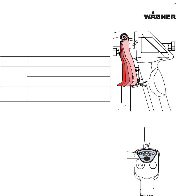
The trigger can be used to activate, one after the other, the various functions of the spray gun.
Distance Description
1AirCoat air opens.
2AirCoat air opened and electrostatic (high-voltage) activated.
 Display (2) for "spray current" on the spray gun
  to
to  activated.
3AirCoat air opened and electrostatic (high-voltage) activated and product valve opened.
4Overall way of trigger.
-An increase in the force needed to pull the trigger back will be perceived at the position where the product valve opens.
-For spraying without high-voltage, the high-voltage can be switched off using the operating button (4). Press the operating button (4) briefly: High-voltage is switched off. The standby display (3) illuminates.
-In the event of a malfunction the spray gun switches to "standby" operating mode and the display (3) illuminates.
-The relationship between forming air and atomizing air is set using the air regulator (16).
1
 2
2
 3
3
4
B_03157
2
3
4
16
B_03262
22
EDITION 05/2015 |
ORDER NUMBER DOC2319150 |
|
OPERATING MANUAL
5.3 PROTECTIVE AND MONITORING EQUIPMENT
The following functions are provided for safety:
-trigger lock (11);
-anti-contact guard for flat jet nozzle (5).
 WARNING
Protective and monitoring equipment!
Risk of injury and damage to the device.
 Protective and monitoring equipment must not be removed, modified or rendered unusable.
 Regularly check for perfect functioning.
 If defects are detected on protective and monitoring equipment, the system must not be operated until these defects are remedied.
5.4 SCOPE OF DELIVERY
Order No. Description
2309871 GM 5000EAC spray gun
Without control unit, product and air hose, electric cable, air cap and nozzle.
Each spray gun includes the following as standard equipment:
Order No. Description
2309368 Assembly tool valve needle
2325263 Assembly tool clamping screw
2319653 Protection gloves against spray mist
2310487 CE Declaration of Conformity
2310481 Operating manual, German
See Chapter 1.3 Operating manual in local language
The spray gun basic version can be adapted optimally to any application depending upon the requirements and the desired accessories with the help of spray gun configuration.
The delivery note shows the exact scope of delivery.
23
EDITION 05/2015 |
ORDER NUMBER DOC2319150 |
|
OPERATING MANUAL
5.5 TECHNICAL DATA
Maximum air pressure |
0.8 MPa; 8 bar; 116 psi |
|
Maximum product pressure |
25 MPa; 250 bar; 3626 psi |
|
Fluid inlet |
NPSM 1/4"-18 |
|
Air connection |
G 1/4" A |
|
Input voltage |
maximum 20 Vpp |
|
Input current |
maximum 1.0 A AC |
|
Output voltage |
maximum 80 kV DC |
|
Output current |
maximum 100 μA DC |
|
Operating temperature range |
0 °C – 40 °C; 32 °F – 104 °F |
|
Maximum permissible product temperature: |
50 °C; 122 °F |
|
Maximum surface temperature |
85 °C; 185 °F |
|
|
Quality standard 6.5.2 according to ISO 8573.1, 2010 |
|
Compressed air quality: free from oil and water |
6: Particle density ≤ 5 mg/m3 |
|
5: Humidity: Pressure dew point ≤ +7 °C |
||
|
||
|
2: Oil content ≤ 0.1 mg/m3 |
|
Weight (without hose set) |
710 g (including union nut, nozzle, air cap and edge filter) |
|
Sound level at 0.3 MPa; 3 bar; 43.5 psi air pressure |
73 dB(A) * |
|
and 11 MPa; 110 bar; 1,549 psi product pressure |
|
*A-rated sound pressure level measured at 1 m distance, LpA1m, in accordance with DIN EN 14462: 2005.
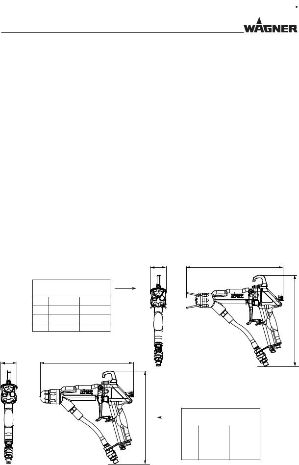
Dimensions |
B |
A |
|
|
|
||
|
GM 5000EAC F |
|
|
|
with flat jet nozzle |
|
|
|
mm |
inch |
|
A |
280 |
11.02 |
|
B |
46 |
1.81 |
|
C |
264 |
10.39 |
|
B |
A |
B_03155 |
C |
GM 5000EAC R |
||||
|
|
|
|
||
|
|
|
with round jet nozzle |
||
|
|
|
|
mm |
inch |
|
|
|
A |
264 |
10.39 |
|
|
|
B |
46 |
1.81 |
|
|
|
C |
264 |
10.39 |
B_03193
C
24
EDITION 05/2015 |
ORDER NUMBER DOC2319150 |
|
OPERATING MANUAL
5.6 SPRAYING PROCEDURE
5.6.1SPRAYING PROCEDURE FOR AIRCOAT ROUND SPRAY
In the AirCoat process, the spray product is atomized under a pressure of 3-15 MPa; 30-150 bar; 435-2,176 psi. With the help of an air pressure of 0-0.25 MPa; 0-2.5 bar; 0-36 psi, a soft, spray jet is produced. The spray jet diameter can be adjusted by turning the nozzle nut.
|
|
AirCoat air |
Nozzle nut |
|
|
Spray product |
|
|
|
AirCoat air |
|
Advantages |
|
|
|
- |
Large application volume |
|
Spray jet |
- |
Low fogging tendency |
"? |
|
|
|
|
|
-Good finish
-High viscosity products can easily be applied
-High endurance of the nozzles
- Jet width adjustment |
Multi-channel swirl |
|
nozzle |
||
|
5.6.2SPRAYING PROCEDURE FOR AIRCOAT FAN SPRAY
In the AirCoat process, the spray product is atomized under a pressure of 3-15 MPa; 30-150 bar; 435-2,176 psi. With the help of the AirCoat air, with a pressure of 0-0.25 MPa; 0-2.5 bar; 0-36 psi, a soft, flat spray jet is produced which largely eliminates the problem of overlapping in the peripheral zones. With shaping air, there is the possibility of reducing the width of the spray jet.
Advantages
-Large application volume
-Low fogging tendency
-Good finish
-High viscosity products can easily be applied
-High endurance of the nozzles
-Jet width adjustment
Variable spray jet width
Shaping air
Air cap
B_00020
Atomizing air
25
EDITION 05/2015 |
ORDER NUMBER DOC2319150 |
|
OPERATING MANUAL
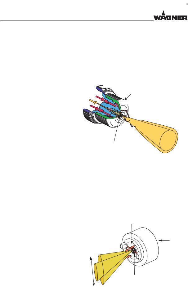
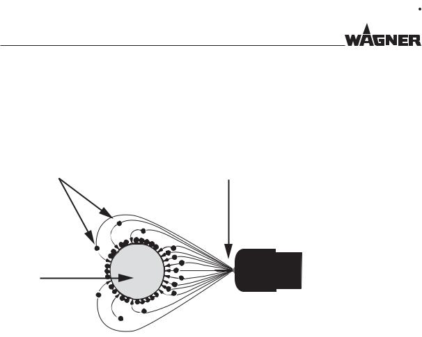
5.6.3ELECTROSTATIC EFFECT
The spray gun produces an electrostatic field by means of the high-voltage electrode. As a result, the paint particles atomized by the spray gun are carried to the grounded work piece by kinetic and electrostatic energy, where they adhere finely dispersed to the object to be sprayed.
Paint particle |
Electrode |
Object to be sprayed
grounded
"?
Advantages
-Very high application effectiveness
-Low over spray
-Coating of entire circumferences due to the electrostatic effect
-Savings in working time
26
EDITION 05/2015 |
ORDER NUMBER DOC2319150 |
|
OPERATING MANUAL
6 ASSEMBLY AND COMMISSIONING
6.1 TRAINING ASSEMBLY/COMMISSIONING STAFF
 WARNING
Incorrect installation/operation!
Risk of injury and damage to the device.
 The assembly and commissioning staff must have the technical skills to safely undertake commissioning.
 When assembling, commissioning and carrying out all work, read and follow the operating manuals and safety regulations for the additionally required system components.
A skilled person must check to ensure that the device is in a reliable state after it is installed and commissioned.
6.2 STORAGE CONDITIONS
Until the point of assembly, the device must be stored in a dry location, free from vibrations and with a minimum of dust. The device must be stored in closed rooms.
The air temperature at the storage location must be between -20 °C and +60 °C (-4 °F and +140 °F).
The relative air humidity at the storage location must be between 10 and 95% (without condensation).
6.3 INSTALLATION CONDITIONS
The air temperature at the installation site must be in a range between 0 and 40 °C; 32 and 132 °F.
The relative air humidity at the installation site must be between 10 and 95% (without condensation).
6.4 ASSEMBLY AND INSTALLATION
Check the delivery package against the delivery note. Become familiar with the function of the spray gun and all the other components used. Carefully read the accompanying operating manual. Note the special requirements of the designated electrostatic AirCoat spray procedure.
27
EDITION 05/2015 |
ORDER NUMBER DOC2319150 |
|
OPERATING MANUAL
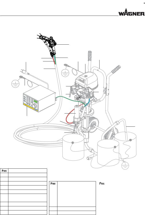
6.4.1TYPICAL ELECTROSTATIC SPRAYING SYSTEM
16
21 15
14
3
R1 |
80 |
|
|
|
60 |
|
|
||
|
100 |
|
||
|
|
|
||
R2 |
40 |
80 |
|
|
20 |
|
|||
|
60 |
|
||
R3 |
10 |
40 |
EXT |
|
kV |
||||
|
20 |
|
||
|
|
|
||
|
|
μA |
|
VM 5000
13
B_03158
Description
1 GM 5000EACF spray gun
2Gun cable
3 Grounding cable
4 Pneumatic pump
5Sliding tables
6Air pressure regulator + air filter
7 Product suction system
8Return hose
9High-pressure filter
1 |
|
|
2 |
3 |
5 |
|
4 |
|
|
|
12
6
11
10 

9
17
7
8
18 |
19 |
|
20
|
Description |
|
|
Description |
10 |
Compressed air connection |
|
17 |
Return valve |
11 |
Stop valve |
|
18 |
Tank for return flow |
12 |
Air pressure regulator |
|
19 |
Paint tank |
13 |
VM 5000 control unit |
|
20 |
Tank for flushing agent |
14 |
Protective hose |
|
21 |
Mains cable |
15Air hose
16Product hose
28
EDITION 05/2015 |
ORDER NUMBER DOC2319150 |
|
OPERATING MANUAL
The GM 5000EAC spray gun must be combined with various components to make up a spraying system (spraypack). The system shown in the figure is only one example of an electrostatic spraying system. Your WAGNER distributor would be happy to assist you in creating a spraying system solution that meets your individual needs. You must familiarize yourself with the operating manuals and the safety regulations of all additional system components before starting commissioning.
 WARNING
Incorrect installation/operation!
Risk of injury and damage to the device.
 When commissioning and for all work, read and follow the operating manual and safety regulations for the additionally required system components.
6.4.2VENTILATION OF THE SPRAY BOOTH
The electrostatic spraying equipment may only be operated in defined spraying areas and in accordance with the EN 12215 standard or under comparable ventilation conditions. The electrostatic spraying equipment must be locked to the technical ventilation so that the coating product supply and the high-voltage are not effective as long as the technical ventilation is not operated with the minimum exhaust air volume flow or a larger exhaust air volume flow.
Ensure that the excess coating product (overspray) will be collected up safely.
 WARNING
Toxic and/or flammable vapor mixtures!
Risk of poisoning and burns.
 Operate the device in a spray booth approved for the working materials.
– or –
 Operate the device on an appropriate spraying wall with the ventilation (extraction) switched on.
 Observe national and local regulations for the outgoing air speed.
29

EDITION 05/2015 |
ORDER NUMBER DOC2319150 |
|
OPERATING MANUAL
30
 Loading...