


 Loading...
VIVOTEK - Built with
 Reliability
RX9401 H.265 Video Receiver
User’s Manual
H.265/H.264 • 16 CH • HDMI • ONVIF


 Rev. 1.6.1.11


 Rev. 1.0


 Rev. 1.1

User's Manual - 1 

VIVOTEK - Built with Reliability
Table of Contents
Chapter One Hardware Installation and Initial Configuration 5
Introducing the Network Video Recorder 5 Special Features 6 Safety 6 Chassis Dimensions 7 Physical Description 8 Topology 9 Hardware Installation 10 Interface Connections 11 Initial Configuration - via a Local Console 12 Initial Configuration - via a Web Console (Optional) 15 LED Indicators 17 Power Up and Power Down 18
Section One Management over a Local Console 19
Chapter Two Introduction to the Local Console Interface 19
2-1. How to Begin 21 2-2. Operation on a Camera View Cell 25 2-2-1. PTZ Panel 25 2-2-2. Digital Zoom Panel 29 2-2-3. Others 30 2-2-4. Right-click Commands 31
Chapter Three Configuation Using the Local Console 32
The Main Control Portal 32 3-1. Layout 32 3-2. Settings 33 3-2-1. Settings - Overview 33 3-2-2. Settings - Camera - Management 34 3-3-1. Settings - System - Information 39 3-3-2. Settings - System - Maintenance 40 3-3-3. Settings - System - Display 41 3-4. Settings - User 42 3-5. Settings - Network 43 Settings - Network - IP 43 Settings - Service 44 3-6. Information 45
Section Two Management over a Web Console 46
Technical Specifications ............................................................................................................................................ |
49 |
Safety and Compatibility............................................................................................................................................ |
51 |
2 - User's Manual
VIVOTEK - Built with Reliability
Revision History
* Rev. 1.0: Initial release.
* Rev. 1.1: Corrected the video feed from camera that is used for streaming.
Technology License Notice
Notices from HEVC Advance:
THIS PRODUCT IS SOLD WITH A LIMITED LICENSE AND IS AUTHORIZED TO BE USED ONLY IN CONNECTION WITH HEVC CONTENT THAT MEETS EACH OF THE THREE FOLLOWING QUALIFICATIONS: (1) HEVC CONTENT ONLY FOR PERSONAL USE; (2) HEVC CONTENT THAT IS NOT OFFERED FOR SALE; AND (3) HEVC CONTENT THAT IS CREATED BY THE OWNER OF THE PRODUCT. THIS PRODUCT MAY NOT BE USED IN CONNECTION WITH HEVC ENCODED CONTENT CREATED BY A THIRD PARTY, WHICH THE USER HAS ORDERED OR PURCHASED FROM A THIRD PARTY, UNLESS THE USER IS SEPARATELY GRANTED RIGHTS TO USE THE PRODUCT WITH SUCH CONTENT BY A LICENSED SELLER OF THE CONTENT. YOUR USE OF
THIS PRODUCT IN CONNECTION WITH HEVC ENCODED CONTENT IS DEEMED ACCEPTANCE OF THE LIMITED AUTHORITY TO USE AS NOTED ABOVE.
H.264
THIS PRODUCT IS LICENSED UNDER THE AVC PATENT PORTFOLIO LICENSE FOR THE PERSONAL AND NON-COMMERCIAL USE OF A CONSUMER TO (i) ENCODE VIDEO IN COMPLIANCE WITH THE AVC STANDARD ("AVC VIDEO") AND/OR (ii) DECODE AVC VIDEO THAT WAS ENCODED BY A CONSUMER ENGAGED IN A PERSONAL AND NON-COMMERCIAL ACTIVITY AND/OR WAS OBTAINED FROM A VIDEO PROVIDER LICENSED TO PROVIDE AVC VIDEO. NO LICENSE IS GRANTED OR SHALL BE IMPLIED FOR ANY OTHER USE. ADDITIONAL INFORMATION MAY BE OBTAINED FROM MPEG LA, L.L.C. SEE HTTP://WWW.MPEGLA.COM
User's Manual - 3
VIVOTEK - Built with Reliability
Read Before Use
The use of surveillance devices may be prohibited by law in your country. The Network Video Receiver is not only a high-performance web-ready camera but can also be part of a flexible surveillance system. It is the user’s responsibility to ensure that the operation of such devices is legal before installing this unit for its intended use.
It is important to first verify that all contents received are complete according to the Package Contents listed below. Take note of the warnings in the Quick Installation Guide before the Network Video Receiver is installed; then carefully read and follow the instructions in the Installation chapter to avoid damage due to faulty assembly and installation. This also ensures the product is used properly as intended.
The Network Video Receiver is a network device and its use should be straightforward for those who have basic networking knowledge. It is designed for various applications including video sharing, video recording, general security/surveillance, etc. The Configuration chapter suggests ways to best utilize the Network Video Recorder and ensure proper operations. For creative and professional developers, the URL Commands of the Network Video Recorder section serves as a helpful reference to customizing existing homepages or integrating with the current web server.
NOTE:
The operating system and management software are installed on a flash memory mounted on the main board. Except for the plug-ins for the onscreen control, there is no need to install software.
Package Contents
■ RX9401 |
■ Mouse |
■ Power adapter |
■ Quick Installation Guide |
|
|
Symbols and Statements in this Document
|
|
i |
|
INFORMATION: provides important messages or advices that might help prevent inconvenient |
|||||
|
|
|
or problem situations. |
||||||
|
|
|
|
|
|
|
|
|
NOTE: Notices provide guidance or advices that are related to the functional integrity of the |
|
|
|
|
|
|
|
|
|
machine. |
|
|
|
|
|
|
|
|
||
|
|
|
|
|
|
|
|
|
Tips: Tips are useful information that helps enhance or facilitate an installation, function, or |
|
|
|
|
|
|
|
|
|
|
|
|
|
|
|
|
|
|
||
|
|
|
|
|
|
|
|
|
process. |
|
|
|
|
|
|
|
|
||
|
|
|
|
|
|
|
|
|
WARNING! or IMPORTANT: These statements indicate situations that can be dangerous or |
|
|
|
|
|
|
|
|
|
hazardous to the machine or you. |
|
|
|
|
|
|
|
|
|
Electrical Hazard: This statement appears when high voltage electrical hazards might occur |
|
|
|
|
|
|
|
|
|
to an operator. |
4 - User's Manual
VIVOTEK - Built with Reliability
Chapter One Hardware Installation and
Initial Configuration
Introducing the Network Video Recorder
VIVOTEK’s RX9401 is an H.265 Single-Channel Ultra-HD Video Receiver. Delivering high-quali- ty and detailed images, it is equipped for up to 16-CH network cameras and a maximum network camera resolution of 8-Megapixels. The RX9401 can drive an HD monitor directly via HDMI, and supports decode options of 4K 30 fps, four H.265 1080p 120 fps, nine H.265 720p 270 fps, or sixteen H.265 D1 480 fps. The RX9401 offers a more cost-effective and PC alternative solution with no costly VMS client fee, no HDD noise and no failure issues. It is suitable for standalone viewers through local viewing. Secured and simplified IT management reduce the requirement for end user training, further reducing long-term costs.
Space-saving, Flexible Installation
Compact size with fanless design for any small scale video surveillance installation, the RX9401 is perfect for a single display application that requires space-saving solutions. For more fexible installation, it supports, wall or desktop mount options.
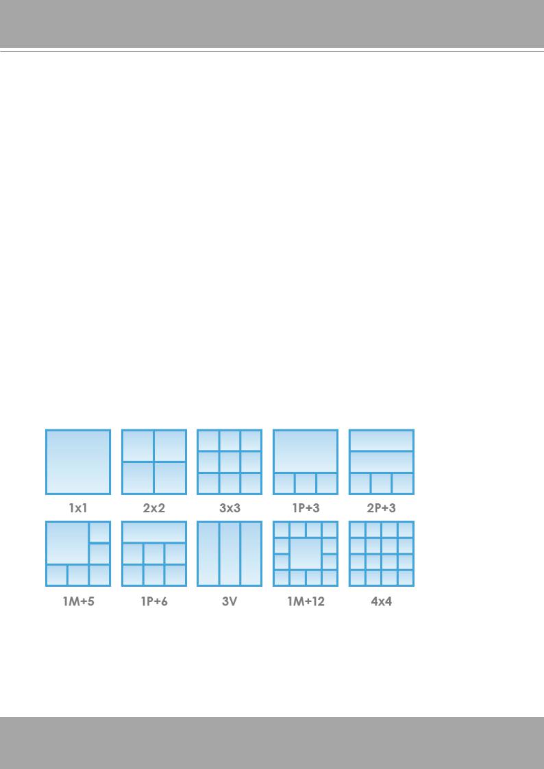
Various Split-window Layout & Fisheye Dewarp Support
The RX9401 provides various split modes for layout display (1x1, 2x2, 3x3, 1P+3, 2P+3, 1M+5, 1P+6, 3V, 1M+12, 4x4) and supports VIVOTEK’s fisheye camera Fisheye Dewarp function, which provides multiple de-warping modes to ensure the correct angle of video view and detailed information for fexible usage.
User's Manual - 5

VIVOTEK - Built with Reliability
Special Features
● Runs on embedded Linux |
● Fisheye Dewarp |
● 1 x HDMI for local display up to 4K resolution |
● Supports cameras of up to 8MP resolution |
● Up to 16 Channel IP Camera Input |
● ONVIF Compliance (Project Support Func- |
|
tion) |
● 1 x Gigabit RJ45 uplink Ethernet port; |
● Supports Various Split-window Layout Dis- |
|
play Modes |
● 2 x USB 2.0 Port (1 in Front / 1 in Back) |
● Snapshot / Export Media |
● Size: 198 mm (W) x 200 mm (D) x 47 mm (H)● PiP Video Control |
|
● One Button Auto Setup |
● Configuration Backup / Restore |
● Compatible with VIVOTEK VAST Central Management Software*
Safety
Connect the system to an earthed main power outlet.
Never open the housing of the power supply unit.
Install and operate the system only in a dry, weather-proof location.
Observe the following safety factors:
•Is there visible damage to the system or power cord?
•Is the system operating correctly?
•Has the system been exposed to rain or moisture?
•Has the system been in a long storage under harsh conditions or exposed to unconforming stress?
The relevant electrical engineering regulations must be complied with at all times during the installation.
Ensure that all maintenance and repair work is handled by qualified personnel such as electrical engineers or network specialists.
Read this manual before installing or operating the system. The documentation contains important safety instructions about permitted uses.
The rated AC input is: 100-240V~ 1.5A, 60-50Hz; the max. consumption: 9.24W (DC12V, 1.5A)
If a fault occurs, disconnect the power cord from the power supply.
Do not install the system close to heaters or other heat sources. Avoid locations with direct sunlight.
All ventilation openings must not be blocked.
Use only the cables shipped with system or use appropriate cables that can withstand electromagnetic interference.
6 - User's Manual
VIVOTEK - Built with Reliability
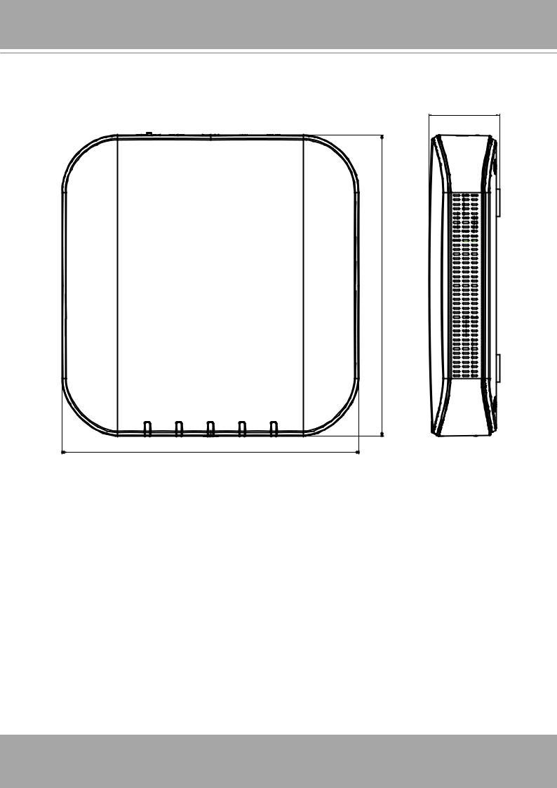
Chassis Dimensions
200 |
198
47 |
User's Manual - 7
VIVOTEK - Built with Reliability
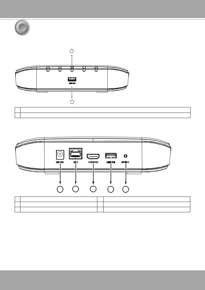
1 Physical Description
 Front View
1
2
1 Activity LED: Please refer to page 17 for LED definitions.
2 USB 2.0 port
 Rear View
1 |
2 |
3 |
4 |
5 |
1 |
Power socket (DC12V, 1.5A) |
4 |
USB port |
2 |
10/100Mbps uplink port |
5 |
Reset button |
3 |
HDMI |
|
|
8 - User's Manual
VIVOTEK - Built with Reliability
 IMPORTANT:
It is important to leave a clearance of 10cm around the chassis. The clearance is required to ensure an adequate airflow through the chassis to ventilate heat.
To ensure normal operation, maintain ambient airflow. Do not block the airflow around chassis such as placing the system in a closed cabinet.
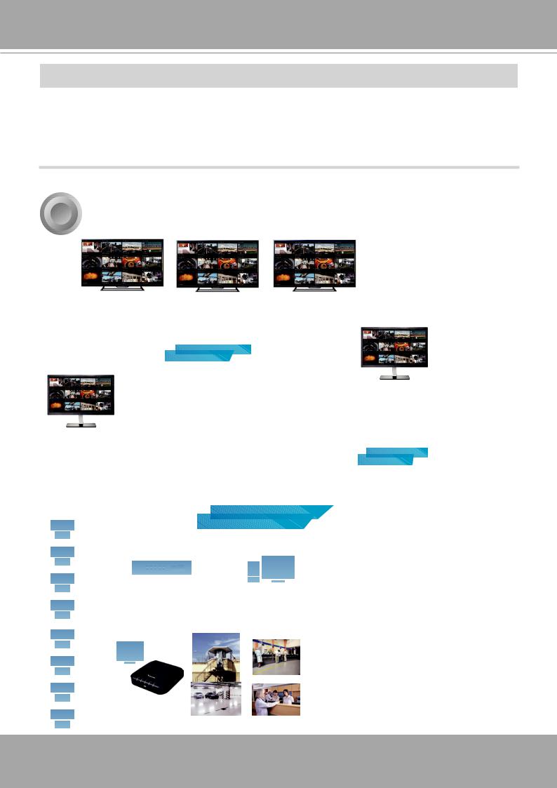
2 Topology
Surveillance center
TV wall
CMS
LAN/WAN |
station |
|
IP cameras
Remote site
NVR
LAN
Recording & Management
LAN
Server Center |
|
Control Center |
NVR |
|
|
|
|
VAST |
Live Monitoring |
Sub Center |
Public Area |
|
||
|
Guard Station |
Banking |
RX9401 |
|
|
|
Parking Station |
Hospital |
User's Manual - 9
VIVOTEK - Built with Reliability
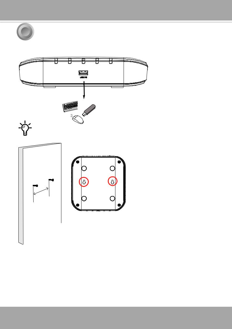
3Hardware Installation
1.Connect a mouse and/or keyboard to the USB connectors at the front or the rear of the receiver.
If you prefer to hang the Receiver on wall, drill and install two screws 104mm apart.
104mm
10 - User's Manual

VIVOTEK - Built with Reliability
4Interface Connections
1.Connect to a monitor using an HDMI cable.
2.Connect CAT5e or better-quality Ethernet cable to the network.
3.Connect USB devices such as mouse, keyboard, or USB thumb drive (formatted in FAT format), or UPS.
4.Connect the power adaptor to the power mains and the system.
LAN/WAN
USB 2.0
AC100~240V 50/60Hz, 1.5A
Pressing the Reset button for longer than 10 seconds will restore the factory detaults.
User's Manual - 11
VIVOTEK - Built with Reliability
5 Initial Configuration - via a Local Console
A local console requires the following:
1.A monitor or TV is connected via an HDMI cable.
2.A mouse and/or a keyboard are connected to the system.
3.It is presumed that the system has not been configured yet. The Installation wizard only appears for an unconfigured machine or one that was restored to its default.
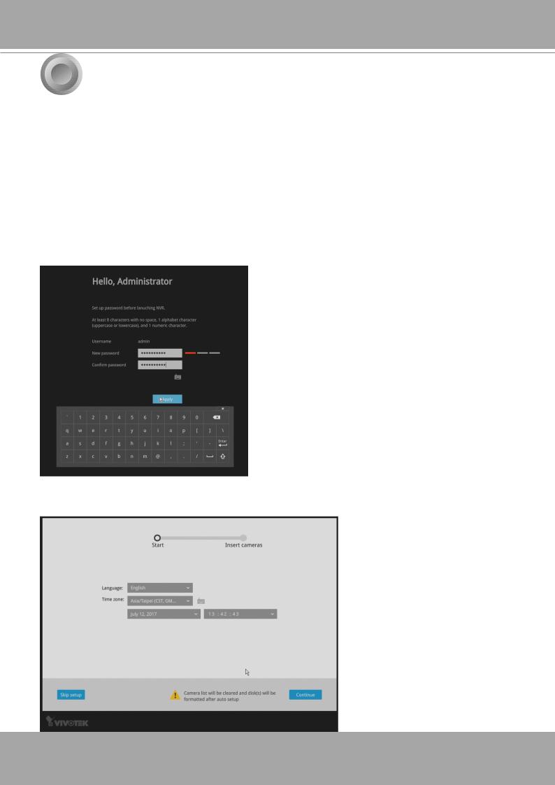
Follow the onscreen messages to complete the initial configuration:
1.When started for the first time, the system will prompt for the forceful configuration of a password. This ensures security from malicious network attack.
The applicable alpha-numeric characters are [0-9][a-z][A-Z][!][$][%][-][.][@][^][_][~], with a max. length of 64 characters.
Click the Apply button when the new password is accepted.
2.Select the UI language, Time zone, and current date and time. Click on the Continue button to proceed.
12 - User's Manual
VIVOTEK - Built with Reliability
 IMPORTANT:
Except in the initial setup, changing system time can produce disruptions to the existing recordings. Turning the current system time back to a time when video recording was taking place can generate duplicate files. And those files may not be playable.
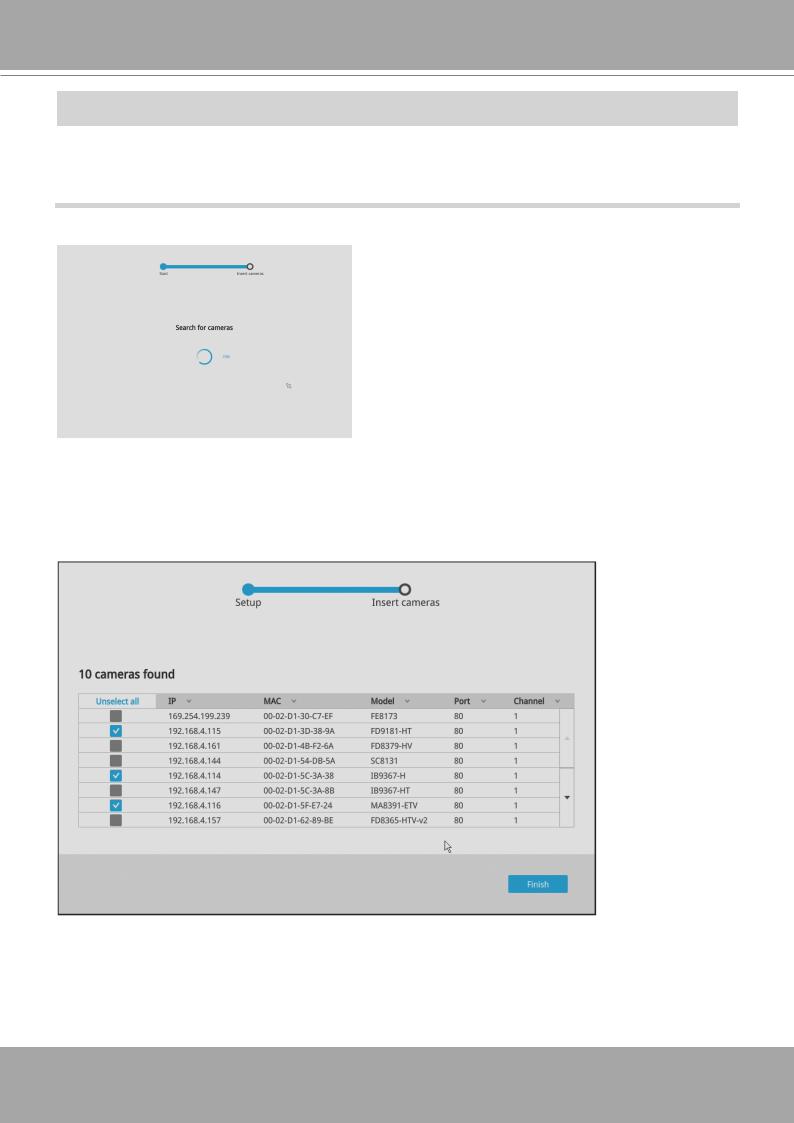
3. The system will then start to scan the local subnet for connected cameras.
4.All cameras detected on the network will be automatically listed. If necessary, deselect the cameras you want to exclude from the configuration.
Cameras properly installed in the same subnet should all be listed. If you cannot find a camera, examine its network connections or network configuration.
User's Manual - 13
VIVOTEK - Built with Reliability
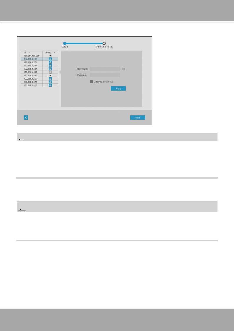
Enter the credentials for each selected cameras on screen. Click Finish to proceed.
 NOTE:
NOTE:
1.The resolution and fps (frame rate per second) of stream 1 may vary depending on the specifications of different cameras.
2.Up to two clients viewing 2x 720P streams is acceptable. If more clients are simultaneously viewing more video streams, the machine can be stressed.
 NOTE:
NOTE:
Although the system supports MAC Binding, the system should be able to detect VIVOTEK's cameras within the network regardless of the presence of a DHCP server. Ideally, cameras and the Receiver should reside in the same subnet. If a camera's IP is changed for some reasons, the system should be able to detect its new IP.
14 - User's Manual
VIVOTEK - Built with Reliability
6Initial Configuration - via a Web Console (Optional)
1.Connec the power cord to start the Receiver. Wait for the system status LED to light green.
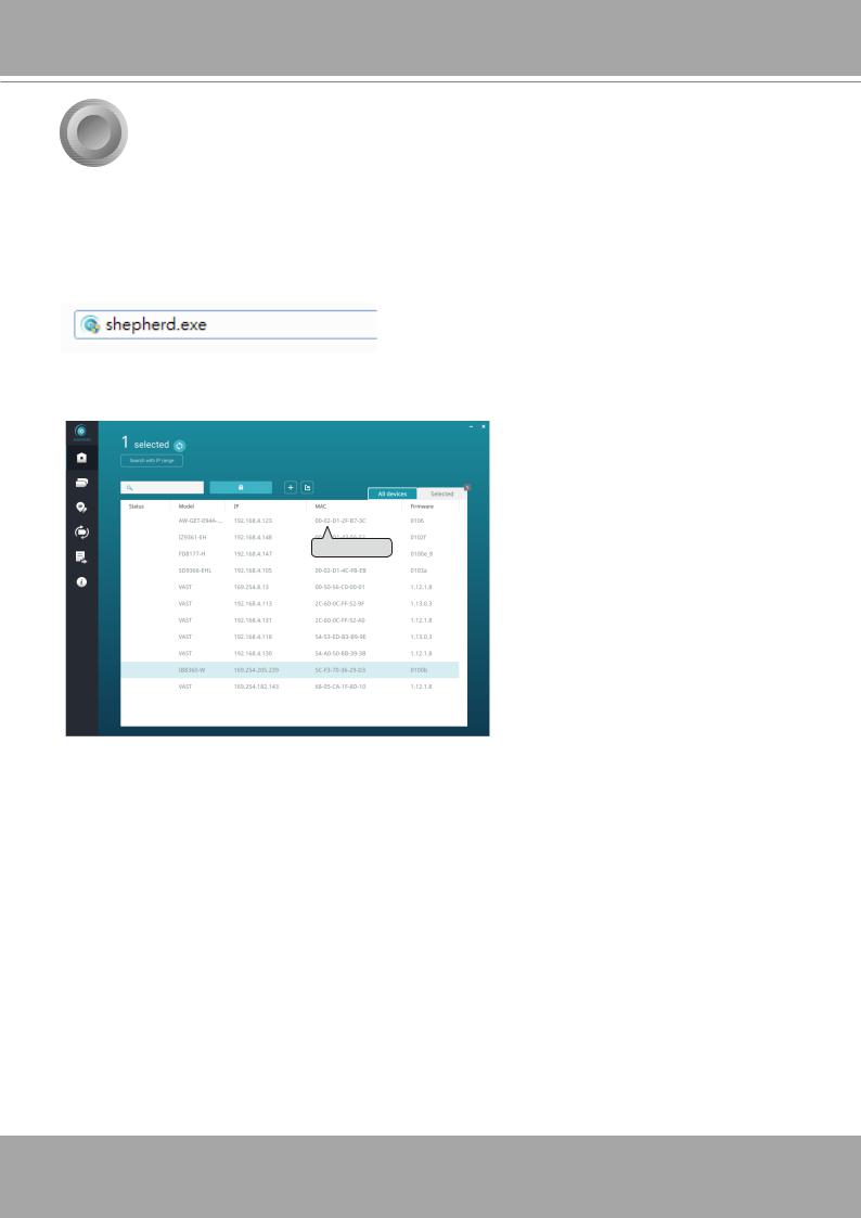
2.From a management computer, download and execute the Shepherd utility software. Follow the onscreen instructions to complete the installation.
3.Start the Shepherd utility. The Shepherd utility will discover the Receiver located in the same subnet.
IB8360RX94 1-W |
192.168.4.151 |
00-02-D1-73-02-02 |
0002D1730202
4. Double-click on the RX9401 entry to start a web session with the Receiver system.
User's Manual - 15
VIVOTEK - Built with Reliability
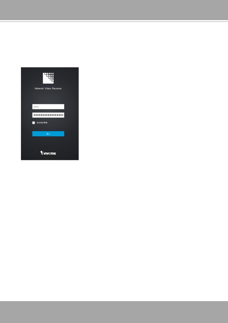
5.If you have configured a user name and password on the local console, use them to log in. Ideally, the initial configuration is performed via the local console. Expand the menu on the right of the Login button. Select and click on the Settings button to begin your configuration.
If accessed for the first time and no password has been configured, enter admin and admin as user name and password.
6. Refer to the later discussions for the rest of the configuration procedure.
16 - User's Manual
Loading...