


 Loading...
IB8360-W Wireless Bullet
Network Camera
User’s Manual
2MP • 12M IR • Smart Stream II • Video Rotation
WiFi • IP66 • UV Protection
 Rev. 1.0:

 Rev. 1.0

VIVOTEK
Table of Contents
Overview |
..............................................................................................................................................................3 |
Revision History 3 Read Before Use 4 Package Contents 4 Symbols and Statements in this Document 5 Physical Description 5 Hardware Installation 7 Software Installation 21 Ready to Use 22
Accessing the Network Camera 23
Using Web Browsers |
23 |
Using RTSP Players |
26 |
Using 3GPP-compatible Mobile Devices |
27 |
Using VIVOTEK Recording Software |
28 |
Main Page ...................................................................................................................................................... |
29 |
Client Settings .................................................................................................................................................. |
34 |
Configuration.................................................................................................................................................... |
39 |
System > General settings |
40 |
System > Homepage layout |
42 |
System > Logs |
45 |
System > Parameters |
47 |
System > Maintenance |
48 |
Media > Image |
52 |
Media > Video |
63 |
Media > Video |
64 |
Network > General settings |
72 |
Network > Streaming protocols |
79 |
Network > SNMP (Simple Network Management Protocol) |
87 |
Network > FTP |
88 |
Wireless > WLAN |
89 |
Wireless > WPS |
91 |
Security > User accounts |
92 |
Security > HTTPS (Hypertext Transfer Protocol over SSL) |
93 |
Security > Access List |
100 |
PTZ > PTZ settings |
105 |
Event > Event settings |
109 |
Applications > Motion detection |
123 |
Applications > Tampering detection |
126 |
Applications > Audio detection |
127 |
Applications > Package management - a.k.a., VADP (VIVOTEK Application Development Platform) |
129 |
Recording > Recording settings |
132 |
Local storage > SD card management |
137 |
Local storage > Content management |
138 |
Appendix |
141 |
2 - User's Manual

VIVOTEK
URL Commands for the Network Camera 141 Technical Specifications 347 Technology License Notice 349 Electromagnetic Compatibility (EMC) 352
Overview
VIVOTEK’s IB8360 and IB8360-W (wireless) are stylish 2-megapixel mini outdoor bullet network cameras, specifically designed for boutique retail applications. Delivering a resolution of 1920x1080 at 30 fps, having IR illuminators effective up to 12 meters, and including SNV technology for low light environments, these remarkable cameras provide users with superior image quality around the clock.
When coupled with VIVOTEK’s Smart Stream II technology, the IB8360/IB8360-W can reduce both bandwidth and storage consumption by up to 50%* while retaining the same superb image quality as a Full HD camera. Built to withstand challenging weather conditions, the IB8360/IB8360-W is armed with weather-proof IP66-rated housing to withstand rain and dust, and ensure smooth operation.
VIVOTEK provides two easy-to-install options for this compact camera; the IB8360-W boasts a 802.11b/g/n compatible wireless connection, and the IB8360 is designed for Power over Ethernet (PoE) functionality. Both cameras were designed and constructed for simple installation and easy connection.
* Depending on scene monitored.
Revision History
■ Rev. 1.0: Initial release.
User's Manual - 3

VIVOTEK
Read Before Use
The use of surveillance devices may be prohibited by law in your country. The Network Camera is not only a high-performance web-ready camera but can also be part of a flexible surveillance system. It is the user’s responsibility to ensure that the operation of such devices is legal before installing this unit for its intended use.
It is important to first verify that all contents received are complete according to the Package Contents listed below. Take note of the warnings in the Quick Installation Guide before the Network Camera is installed; then carefully read and follow the instructions in the Installation chapter to avoid damage due to faulty assembly and installation. This also ensures the product is used properly as intended.
The Network Camera is a network device and its use should be straightforward for those who have basic networking knowledge. It is designed for various applications including video sharing, general security/surveillance, etc. The Configuration chapter suggests ways to best utilize the Network Camera and ensure proper operations. For creative and professional developers, the URL Commands of the Network Camera section serves as a helpful reference to customizing existing homepages or integrating with the current web server.
Package Contents
■IP8360-W and camera stand
■Screws and anchors
■Power adaptor
■Quick Installation Guide
4 - User's Manual
VIVOTEK
Symbols and Statements in this Document
|
i |
|
INFORMATION: provides important messages or advices that might help prevent |
||||
|
|
inconvenient or problem situations. |
|||||
|
|
|
|
|
|
|
NOTE: Notices provide guidance or advices that are related to the functional integrity of |
|
|
|
|
|
|
|
the machine. |
|
|
|
|
|
|
|
Tips: Tips are useful information that helps enhance or facilitae an installation, function, |
|
|
|
|
|
|
|
|
|
|
|
|
|
|
|
|
|
|
|
|
|
|
|
or process. |
|
|
|
|
|
|
|
WARNING: or IMPORTANT:: These statements indicate situations that can be |
|
|
|
|
|
|
|
dangerous or hazardous to the machine or you. |
|
|
|
|
|
|
|
Electrical Hazard: This statement appears when high voltage electrical hazards might |
|
|
|
|
|
|
|
occur to an operator. |
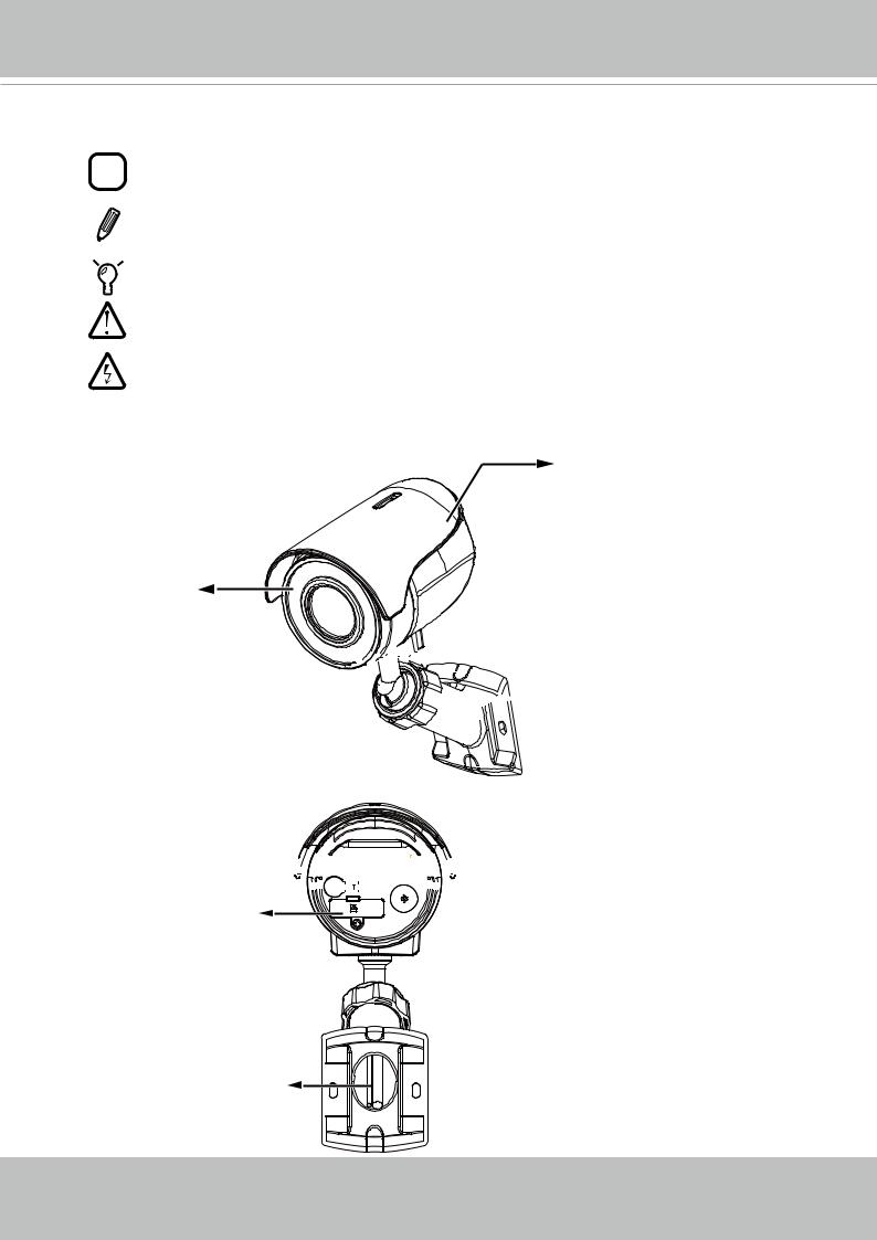
Physical Description
Sun shield
 Front View
IR LED
Lens 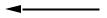

Status LED 


 Fastening ring
 Rear View
WPS / Reset / Restore 


 button


MicroSD/SDHC/SDXC Card slot
12V DC power cord
User's Manual - 5
VIVOTEK
Dimension Drawing
98.33
74.98
163.73
 NOTE:
NOTE:
•Use the camera only with a DC power supply that is UL listed, and limited power source (LPS) certified. The power supply should bear the UL listed and LPS marks.
The power supply must also meet any safety and compliance requirements for the country of use.
•When installing the camera, do not use excessive force.
6 - User's Manual
VIVOTEK
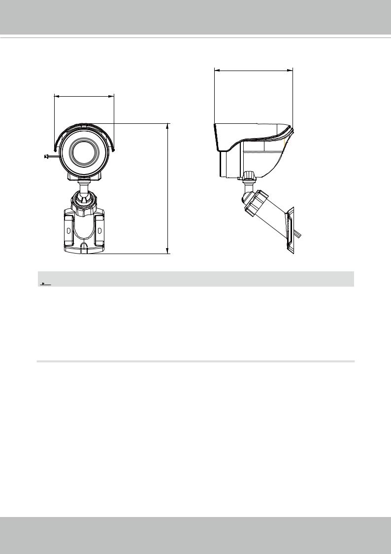
Hardware Installation
1.Jot down the camera's MAC address for later reference.


 XXXXXX


 0002D10766AD
2.Find an appropriate position. Drill holes on the wall for the included plastic anchors. Install the camera by driving screws through the mounting holes on the bracket. The anchors may not be necessary if you install the camera on a wooden wall or calcium silicate board. If preferred, drill a routing hole on the wall for routing the power cord.
If you need to route cables along the wall, use a pincer to remove the break-off tabs.
< 10 kgf-cm
User's Manual - 7
VIVOTEK
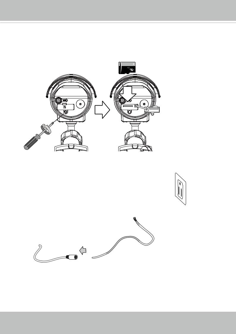
3.Install a MicroSD card if onboard storage is preferred. The card slot is accessed through a rubber seal. Use a small Phillips screwdriver to open the seal.
Please properly fasten the seal and screw after the installation to ensure it is waterproof.
64GB 10
 1
1
I
4. Connect the included power adaptor between the camera and the power mains.
8 - User's Manual
VIVOTEK
 IMPORTANT:
Refer to the functional description and LED definitions below when configuring the camera.
WPS Button Usage |
|
Function |
LED Behavior |
- |
White - operating in AP mode (default status). |
Reset - press less than 3 seconds, |
Off then Red, then White. |
WPS - press 3 to 5 secs, |
Flashing Blue for 2 mins, then Red, then Green. |
Restore default - press longer than 7 secs. |
Flashing Red and Green |
LED Definitions
LED Color |
Indication |
Steady Red |
Power on and system booting |
All LED off |
Power off |
Blink Red / Green every 0.15 sec |
Upgrading F/W |
Blink Orange every 0.15 sec |
Restoring default |
Blink Green every 1 sec |
Wireless AP linked |
Blink Blue every 0.15 sec |
WPS searching |
Blink White every 0.5 sec |
Operating in AP mode |
Steady Red |
Network Failed |
Blink Red / Green every 1 sec |
Connected to network |
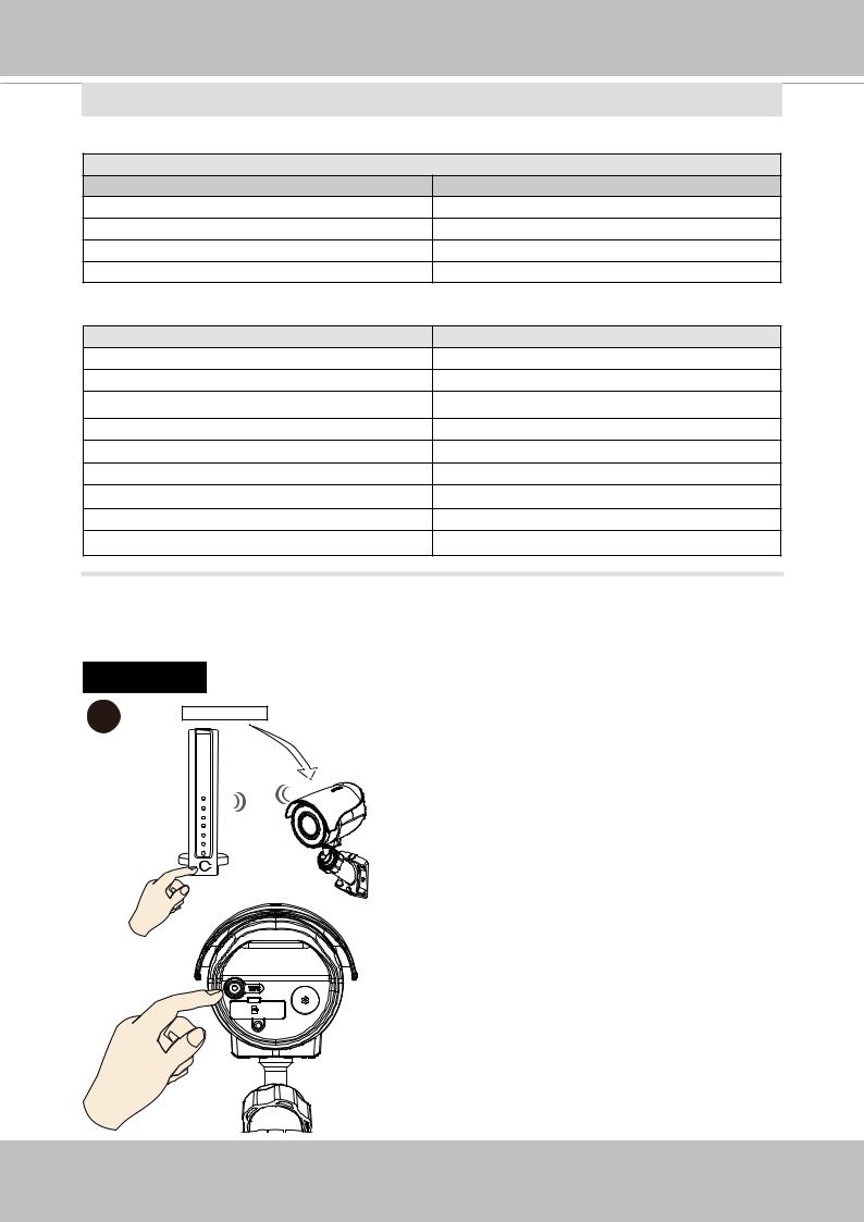
5.Connecting to network. There are 3 different ways to connect the camera to a wireless network.
A:WPS
A-1 |
WEP or WPA-PSK |
A-1. Press the WPS button for 3 to 5 |
|
||
|
|
seconds. You may need to use your |
|
|
finger nail to press. |
|
|
A-2. Press the WPS button on your |
|
|
wireless AP (router). Some router/ |
|
|
AP have a virtual button on their |
|
WPS |
management software instead. Refer |
|
AP |
to your AP's documentation for details |
|
using its WPS function. |
|
|
|
|
WPS |
|
When WPS configuration is done, |
|
wireless connectivity will be established |
|
|
|
3 ~ 5secs and the security encryption, such as |
|
|
WEP or WPA-PSK, will be synchronized |
|
|
with the AP. Install and use VIVOTEK's |
|
|
IW2 utility to find the camera. By default, |
|
|
the camera's firmware uses the DHCP |
|
|
client mode. |
User's Manual - 9
VIVOTEK
 NOTE:
NOTE:
1.WPS may not work if your AP is configured with a "hidden" SSID.
2.If no WPS-enabled AP is detected, the camera will repeat trying to connect by every 20 seconds. If the camera still can not detect an AP after 2 minutes, the wireless setup will be cancelled.
3.If a camera is assigned with a fiex IP outside the AP's network segment, wireless configuration will fail.
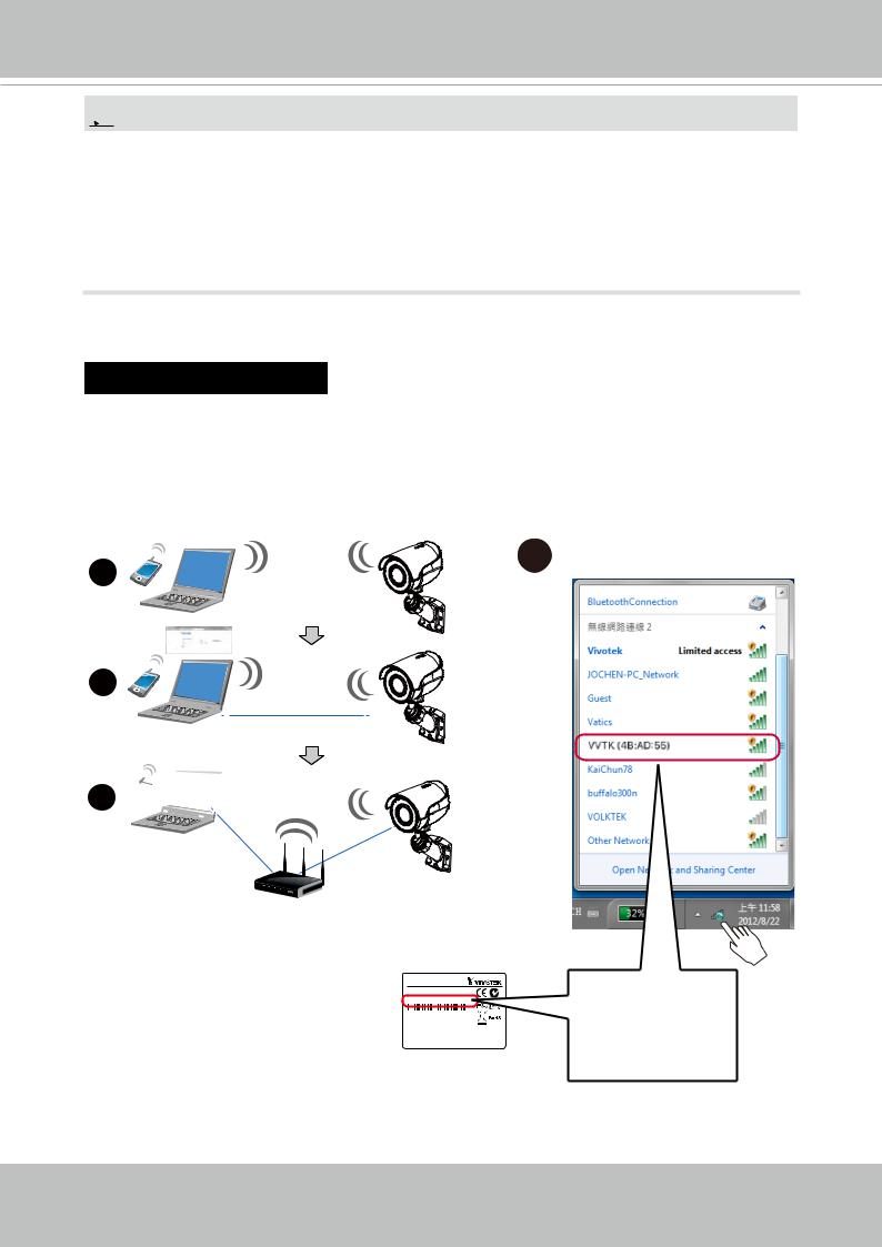
B: WiFi w/o WPS
B-1. When your device has wireless connectivity, e.g., a notebook. Use it to connect search and connect the camera. The camera comes using the AP mode as the default.
B-2. Search your wireless network. You should be able to find the camera displayed as "VVTK and the last 3 octets of the MAC address."
1
2
3 

B-1
AP mode
Client mode
AP
Network Camera
Model No: XXXXXX
MAC: 0002D14BAD55
This device complies with part 15 of the FCC Rules the following two conditions:
(1)this device may not cause harmful interference,
(2)this device must accept any interference
that may cause undesired operation.
Pat. 6,930,709
MAC 4B:AD:55
10 - User's Manual
VIVOTEK
B-2. Select the camera and right-click to display the Connect button. Click to connect.
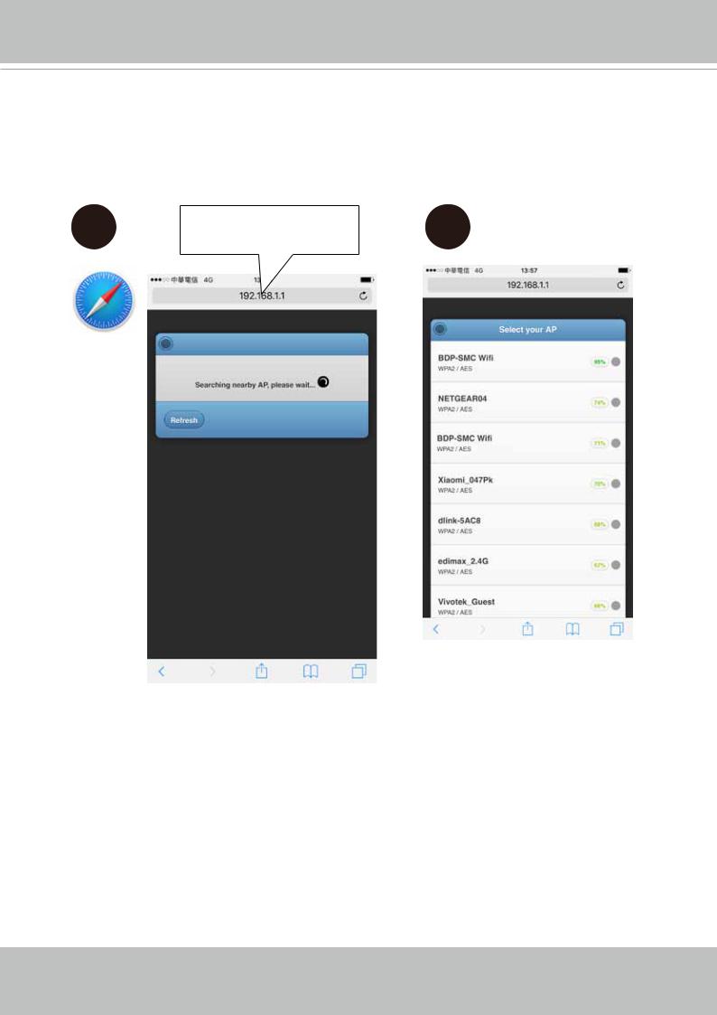
B-3. Open a web browser, enter the camera's default IP: 192.168.1.1.
B-2 |
B-3 |
192.168.1.1
B-4. The camera will search for the other APs within the network. Select an AP you prefer your camera to connect to.
B-5. Enter the credentials for log in to your AP. Please move to Step 6.
B-4 |
B-5 |
 6
6
User's Manual - 11
VIVOTEK
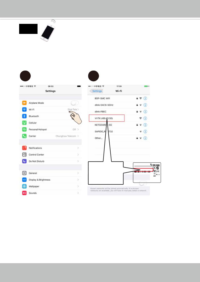
C:
C-1. You can also use your cell phone to connect the camera. Open your Wi-Fi setting page.
C-2. You should be able to find the camera displayed as "VVTK and the last 3 octets of the MAC address." Identify the camera using its MAC address.
C-1 |
C-2 |
MAC 4B:AD:55
Camera
XXXXXX 0002D14BAD55
with part 15 of the FCC Rules. Operation is subject to conditions:
not cause harmful interference, and
accept any interference received, including interference undesired operation.
Made in Taiwan
12 - User's Manual
VIVOTEK
C-3. Open a web browser window. Enter the camera's default IP: 192.168.1.1.
C-4. The camera will search for the other APs within the network. Select an AP you prefer your camera to connect to.
C-3 |
192.168.1.1 |
C-4 |
User's Manual - 13

VIVOTEK
C-5. Enter the credentials for log in to your AP.
C-6. When the camera is connected to an AP, it enters the client mode. You should then install and open the iViewer utility from your app store.
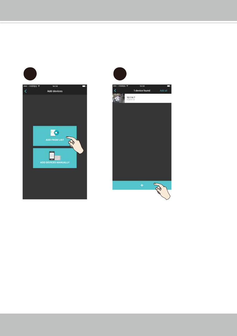
C-7. Add the camera to your iView utility.
C-5 |
C-6 |
C-7 |
iViewer
14 - User's Manual
VIVOTEK
C-8. You can click on Add from List. The iViewer will search within your current network for the camera.
C-9. Once found, you can add the camera into your configuration. Please refer to the documentation that came with iViewer for information.
C-8 |
C-9 |
User's Manual - 15
VIVOTEK
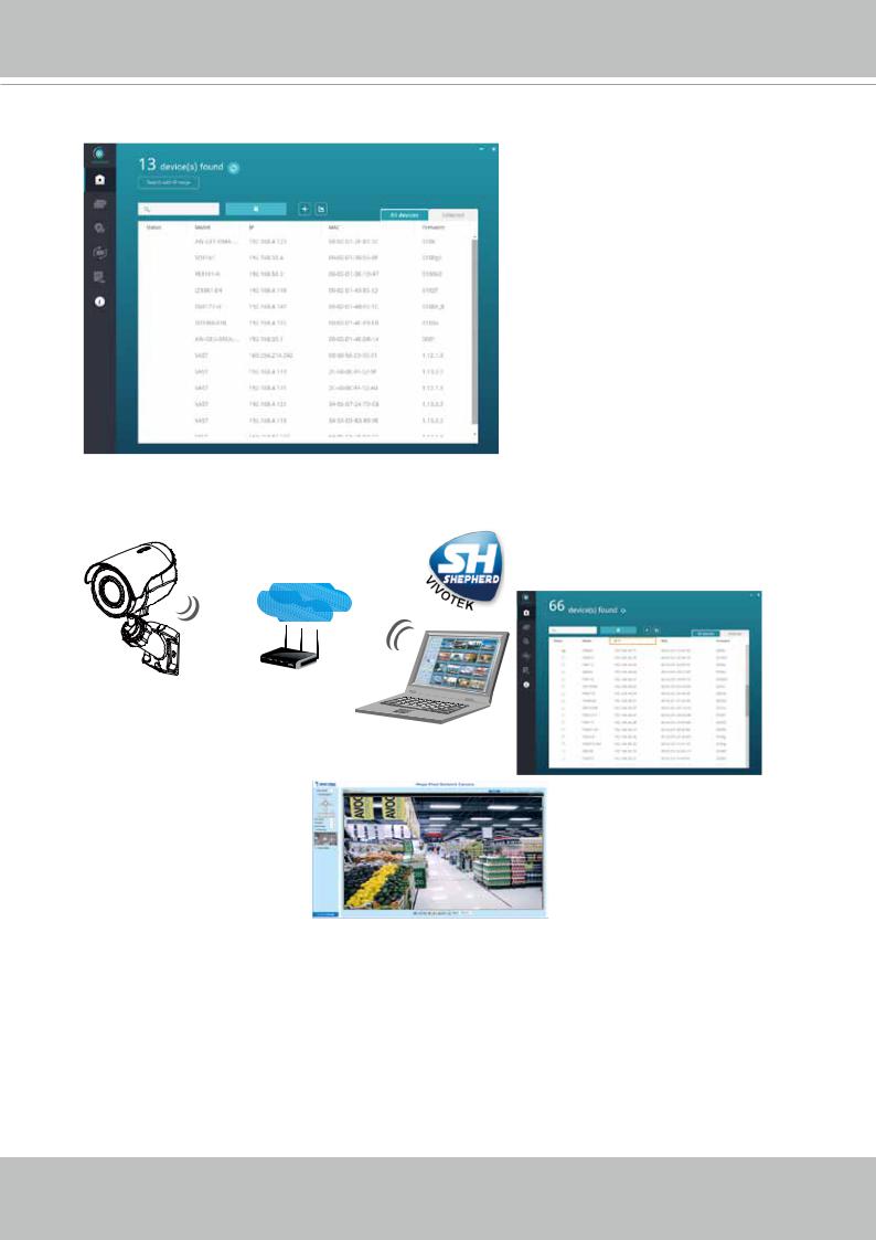
6.Open the Shepherd utility. The utility will search for cameras within the network.
7.Double-click on the camera to open a web console with the camera. You can now start viewing the live stream.
Shepherd
LAN
Browser
16 - User's Manual
VIVOTEK
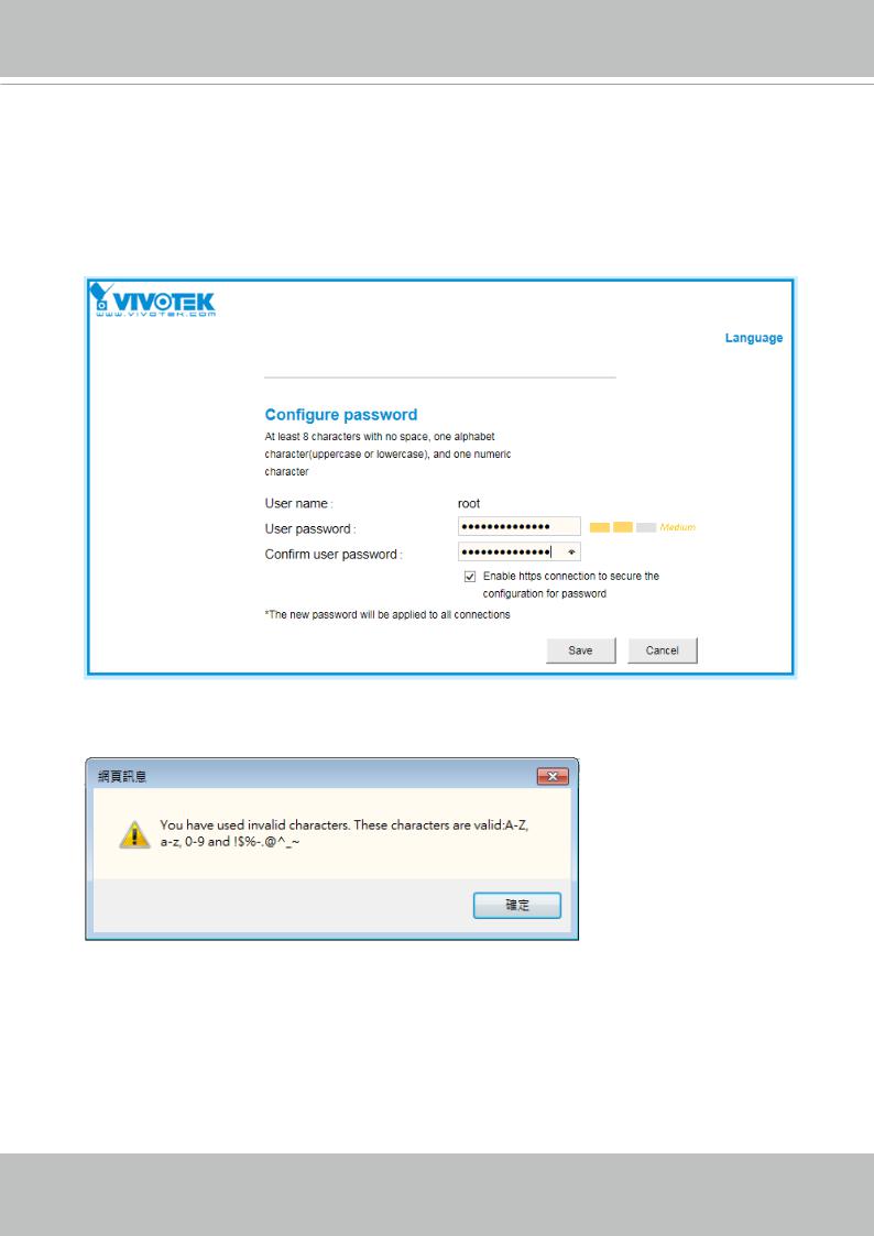
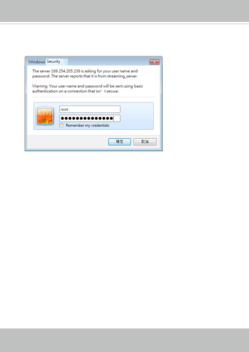
Forceful Password Configuration
The first time you log in to the camera, the firmware will prompt for a password configuration for security concerns.
Enter the combination of alphabetic and numeric characters to fulfill the password strength. requirement. The default name for the camera administrator is “root”, and can not be changed.
Some, but not all special ASCII characters are supported: !, $, %, -, ., @, ^, _, and ~. You can use them in the password combination.
User's Manual - 17
VIVOTEK
Another prompt will request for the password you configured. Enter the password and then you can start configure your camera and see the live view.
18 - User's Manual
VIVOTEK
SD/SDHC/SDXC Card Capacity
This network camera is compliant with SD/SDHC/SDXC 16GB / 8GB / 32GB / 64GB and other preceding standard SD cards.
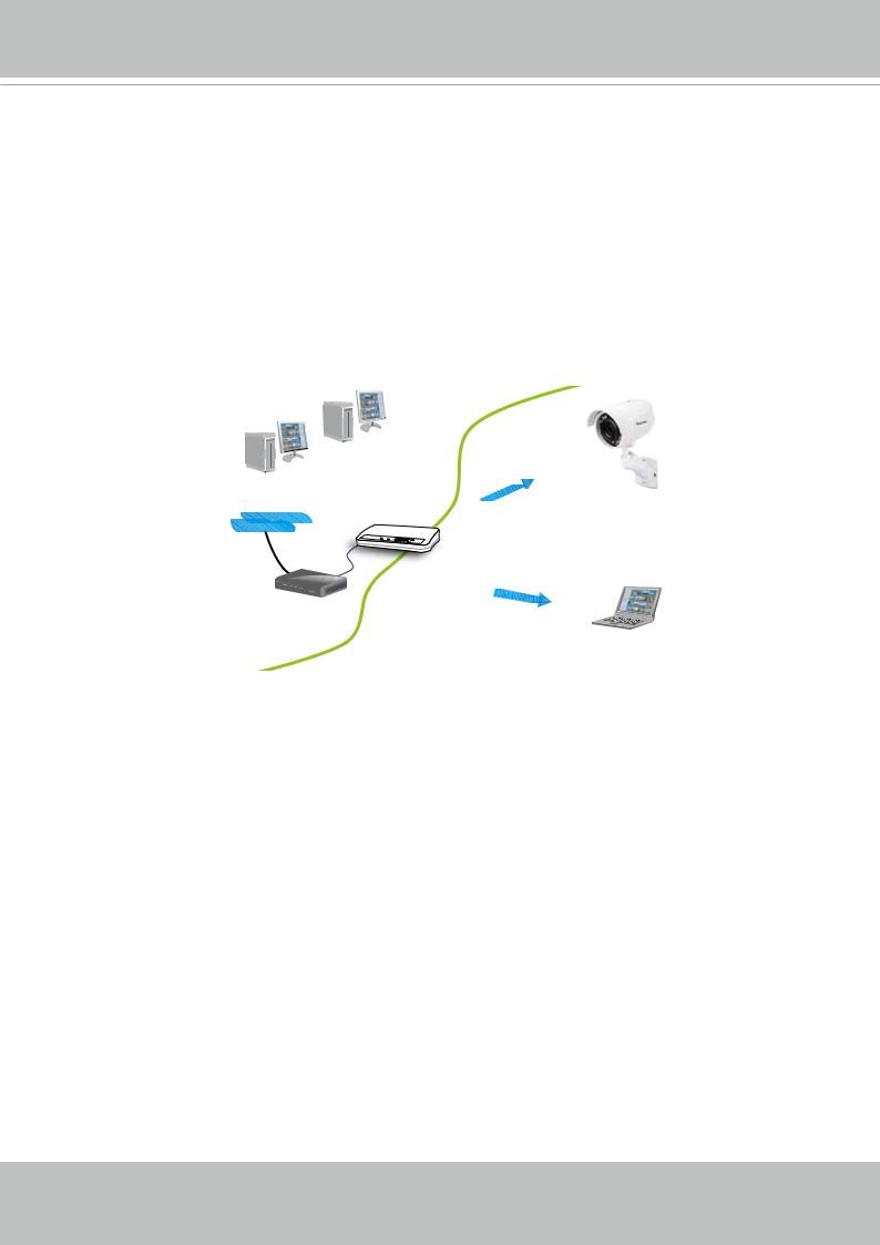
Internet connection via a router
Before setting up the Network Camera over the Internet, make sure you have a router and follow the steps below.
1.Connect your Network Camera behind a router, the Internet environment is illustrated below. Regarding how to obtain your IP address, please refer to Software Installation on page 21 for details.
Internet
WAN (Wide Area Network )
Router IP address : from ISP
LAN (Local Area Network)
Router IP address : 192.168.0.1
IP address : 192.168.0.3 Subnet mask : 255.255.255.0 Default router : 192.168.0.1
Cable or DSL Modem
IP address : 192.168.0.2
Subnet mask : 255.255.255.0
Default router : 192.168.0.1
2.In this case, if the Local Area Network (LAN) IP address of your Network Camera is
192.168.0.3, please forward the following ports for the Network Camera on the router.
■HTTP port: default is 80
■RTSP port: default is 554
■RTP port for video: default is 5556
■RTCP port for video: default is 5557
If you have changed the port numbers on the Network page, please open the ports accordingly on your router. For information on how to forward ports on the router, please refer to your router’s user’s manual.
3. Find out the public IP address of your router provided by your ISP (Internet Service
Provider).
Use the public IP and the secondary HTTP port to access the Network Camera from the
Internet. Please refer to Network Type on page 73 for details.
Internet connection with static IP
Choose this connection type if you are required to use a static IP for the Network Camera.
Please refer to LAN setting on page 72 for details.
User's Manual - 19
VIVOTEK
Internet connection via PPPoE (Point-to-Point over Ethernet)
Choose this connection type if you are connected to the Internet via a DSL Line. Please refer to
PPPoE on page 73 for details.
Configure the router, virtual server or firewall, so that the router can forward any data coming into a pre-configured port number to a network camera on the private network, and allow data from the camera to be transmitted to the outside of the network over the same path.
From |
Forward to |
122.146.57.120:8000 |
192.168.2.10:80 |
122.146.57.120:8001 |
192.168.2.11:80 |
... |
... |
When properly configured, you can access a camera behind the router using the HTTP request such as follows: http://122.146.57.120:8000
If you change the port numbers on the Network configuration page, please open the ports accordingly on your router. For example, you can open a management session with your router to configure access through the router to the camera within your local network. Please consult your network administrator for router configuration if you have troubles with the configuration.
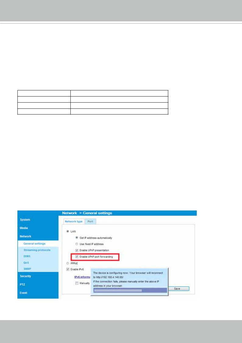
For more information with network configuration options (such as that of streaming ports), please refer to Configuration > Network Settings. VIVOTEK also provides the automatic port forwarding feature as an NAT traversal function with the precondition that your router must support the UPnP port forwarding feature.
20 - User's Manual
VIVOTEK
Software Installation
Installation the Shepherd utility, a software included in the product CD, helps you set up your
Network Camera on the LAN. If your camera comes without the CD, go to VIVOTEK’s website, and locate the utility in the Downloads > Software page.
1.Run the Shepherd utility.
2.The program will conduct an analysis of your network environment.
User's Manual - 21
VIVOTEK
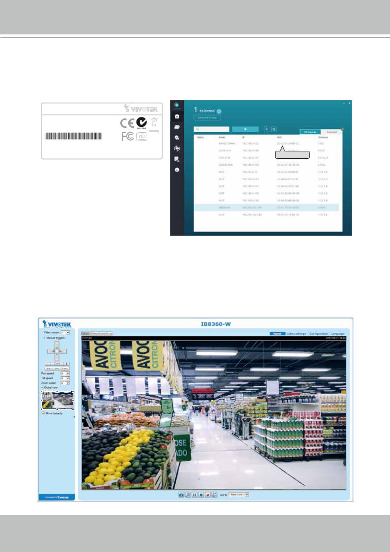
3.The program will search for all VIVOTEK network devices on the same LAN.
4.After a brief search, the installer window will prompt. Click on the MAC and model name that matches the one printed on the product label. You can then double-click on the address to open a management session with the Network Camera.
Network Camera
Model No: IP8360-W
MAC:0002D1730202 RoHS
This device complies with part 15 of the FCC rules. Operation is subject to the following two conditions: |
IB8360-W |
192.168.4.151 |
00-02-D1-73-02-02 |
|
(1)This device may not cause harmful interference, and |
|
|
|
|
(2) this device must accept any interference received, including interference that may cause undesired operation. |
|
|
|
|
Pat. 6,930,709 |
Made in Taiwan |
|
|
0002D1730202 |
Ready to Use
1.A browser session with the Network Camera should prompt as shown below.
2.You should be able to see live video from your camera. You may also install the
32-channel recording software from the software CD in a deployment consisting of multiple cameras. For its installation details, please refer to its related documents.
22 - User's Manual
VIVOTEK
Accessing the Network Camera
This chapter explains how to access the Network Camera through web browsers, RTSP players,
3GPP-compatible mobile devices, and VIVOTEK recording software.
Using Web Browsers
Use Installation Wizard 2 (IW2) to access the Network Cameras on LAN.
If your network environment is not a LAN, follow these steps to access the Netwotk Camera:
1.Launch your web browser (e.g., Microsoft® Internet Explorer or Mozilla Firefox).
2.Enter the IP address of the Network Camera in the address field. Press Enter.
3.Live video will be displayed in your web browser.
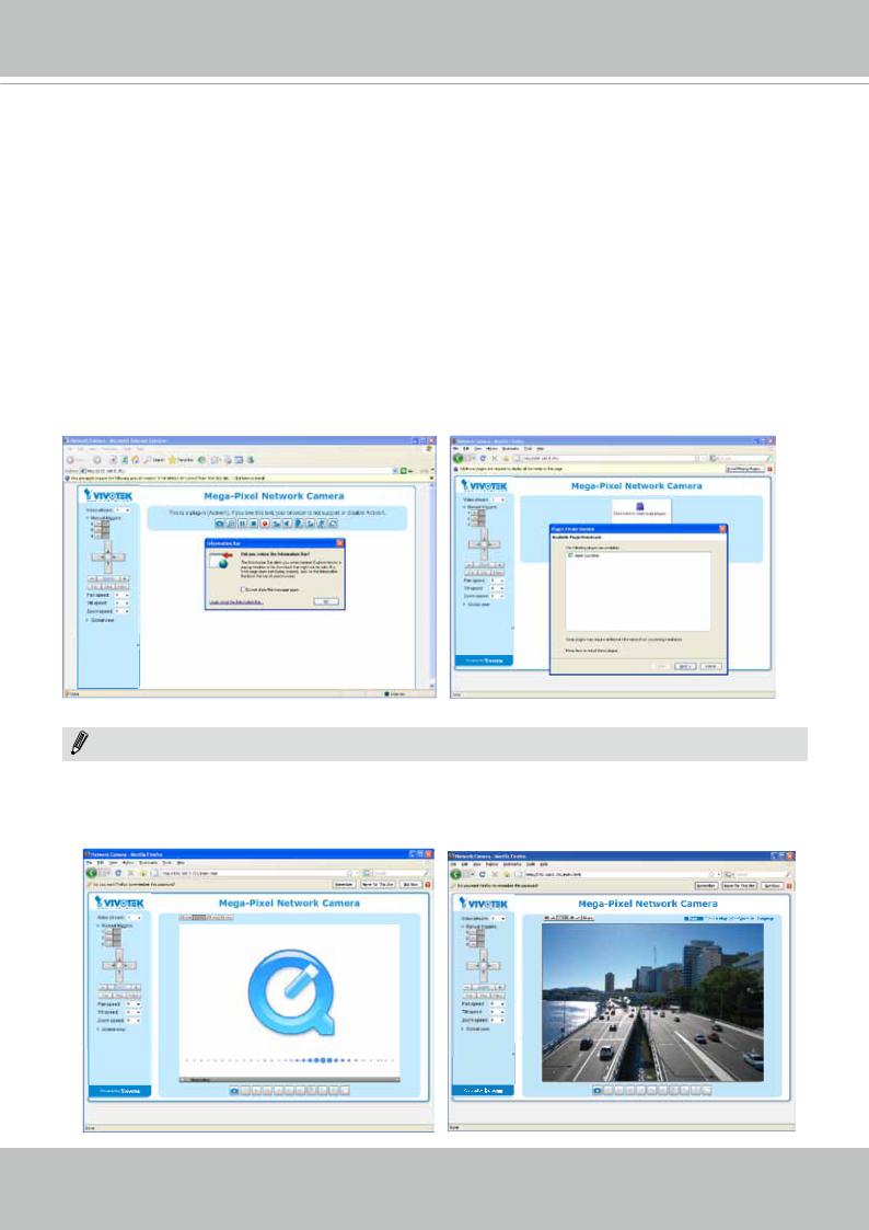
4.If it is the first time installing the VIVOTEK network camera, an information bar will prompt as shown below. Follow the instructions to install the required plug-in on your computer.
NOTENOTE:
► For Mozilla Firefox or Chrome users, your browser will use QuickTime to stream the live video. If you don’t have QuickTime on your computer, please download it first, then launch the web browser.
User's Manual - 23
VIVOTEK
►By default, the Network Camera is not password-protected. To prevent unauthorized access, it is highly recommended to set a password for the Network Camera.
For more information about how to enable password protection, please refer to Security on page 92.
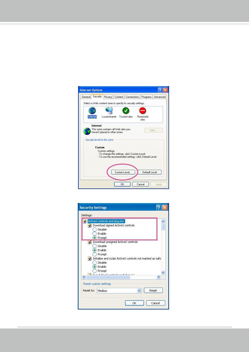
►If you see a dialog box indicating that your security settings prohibit running ActiveX ®
Controls, please enable the ActiveX® Controls for your browser.
1. Choose Tools > Internet Options > Security > Custom Level.
2. Look for Download signed ActiveX® controls; select Enable or Prompt. Click OK.
3. Refresh your web browser, then install the ActiveX® control. Follow the instructions to complete installation.
24 - User's Manual
VIVOTEK
 IMPORTANT:
•Currently the Network Camera utilizes a 32-bit ActiveX plugin. You CAN NOT open a management/view session with the camera using a 64-bit IE browser.
•If you encounter this problem, try execute the Iexplore.exe program from C:\Windows\
SysWOW64. A 32-bit version of IE browser will be installed.
•On Windows 7, the 32-bit explorer browser can be accessed from here:
C:\Program Files (x86)\Internet Explorer\iexplore.exe
• If you open a web session from the IW2 utility, a 32-bit IE browser will be opened.


 Tips:
Tips:
1.The onscreen Java control can malfunction under the following situations: A PC connects to different cameras that are using the same IP address (or the same camera
running different firmware versions). Removing your browser cookies will solve this problem.
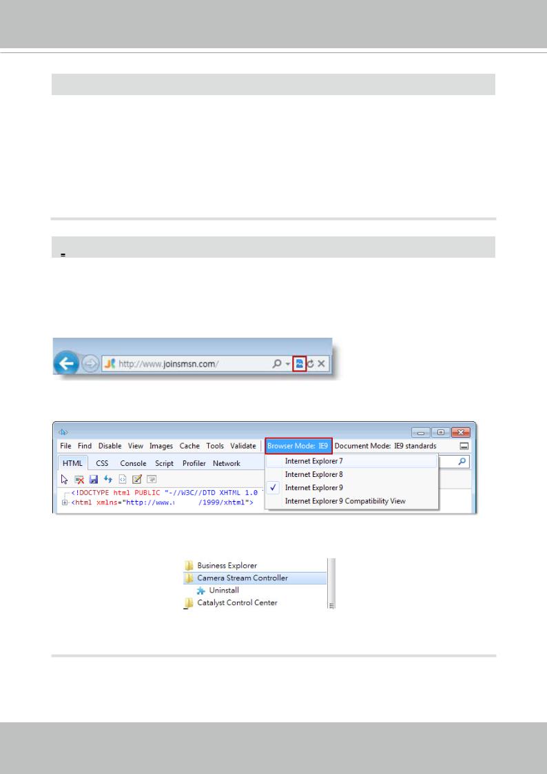
2.If you encounter problems with displaying the configuration menus or UI items, try disable the Compatibility View on IE8 or IE9.
You may also press the F12 key to open the developer tools utility, and then change the
Browser Mode to the genuine IE8 or IE9 mode.
•In the event of plug-in compatibility issues, you may try to uninstall the plug-in that was previously installed.
User's Manual - 25
VIVOTEK
Using RTSP Players
To view the streaming media using RTSP players, you can use one of the following players that support RTSP streaming.
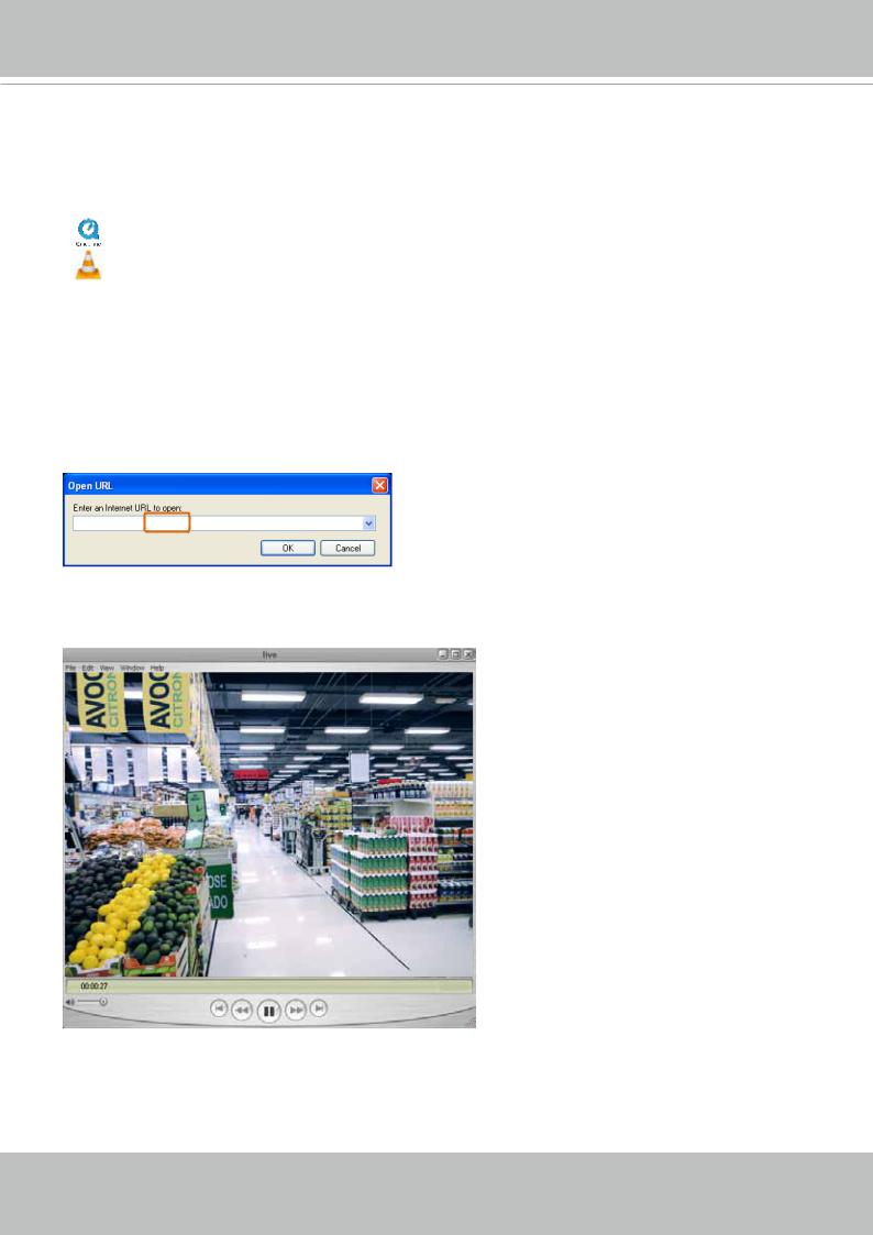
Quick Time Player
VLC media player
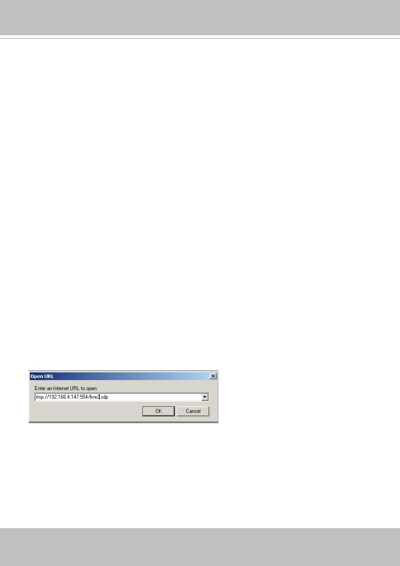
VLC media player 1. Launch the RTSP player.
2. ChoosempegableFile > OpenPlayerURL. A URL dialog box will pop up.
3. The address format is rtsp://<ip address>:<rtsp port>/<RTSP streaming access name for pvPlayer
stream1 or stream2>
As most ISPs and players only allow RTSP streaming through port number 554, please set the
RTSP port to 554. For more information, please refer to RTSP Streaming on page 80.
For example:
rtsp://192.168.5.151:554/live.sdp
4. The live video will be displayed in your player.
For more information on how to configure the RTSP access name, please refer to RTSP Streaming on page 80 for details.
26 - User's Manual
VIVOTEK
Using 3GPP-compatible Mobile Devices
To view the streaming media through 3GPP-compatible mobile devices, make sure the Network
Camera can be accessed over the Internet. For more information on how to set up the Network
Camera over the Internet, please refer to Setup the Network Camera over the Internet on page
19.
To utilize this feature, please check the following settings on your Network Camera:
1. Because most players on 3GPP mobile phones do not support RTSP authentication, make sure the authentication mode of RTSP streaming is set to disable.
For more information, please refer to RTSP Streaming on page 80.
2. As the the bandwidth on 3G networks is limited, you will not be able to use a large video size.
Please set the video streaming parameters as listed below.
For more information, please refer to Stream settings on page 63.
Video Mode |
H.264 |
Frame size |
176 x 144 |
Maximum frame rate |
5 fps |
Intra frame period |
1S |
Video quality (Constant bit rate) |
40kbps |
3. As most ISPs and players only allow RTSP streaming through port number 554, please set the RTSP port to 554. For more information, please refer to RTSP Streaming on page 80.
4. Launch the player on the 3GPP-compatible mobile devices (e.g., QuickTime).
5. Type the following URL commands into the player.
The address format is rtsp://<public ip address of your camera>:<rtsp port>/<RTSP streaming access name for stream # with small frame size and frame rate>.
For example:
You can configure Stream #2 into the suggested stream settings as listed above for live viewing on a mobile device.
User's Manual - 27

VIVOTEK
Using VIVOTEK Recording Software
The product software CD also contains a VAST recording software, allowing simultaneous monitoring and video recording for multiple Network Cameras. Please install the recording software; then launch the program to add the Network Camera to the Channel list. For detailed information about how to use the recording software, please refer to the user’s manual of the software or download it from http://www.vivotek.com.


 Tips:
Tips:
1.If you forget the root (administrator) password for the camera, you can restore the camera defaults by pressing the reset button for longer than 7 seconds.
2.If DHCP is enabled in your network, and the camera cannot be accessed, run the Shepherd utility to search the network. If the camera has been configured with a fixed IP that does not comply with your local network, you may see its default IP 169.254.x.x. If you still cannot find the camera, you can restore the camera to its factory defaults. The factory default is DHCP client.
3.If you change your network parameters, e.g., added a camera via a connection to a LAN card, re-start the Shepherd utility.
28 - User's Manual
VIVOTEK
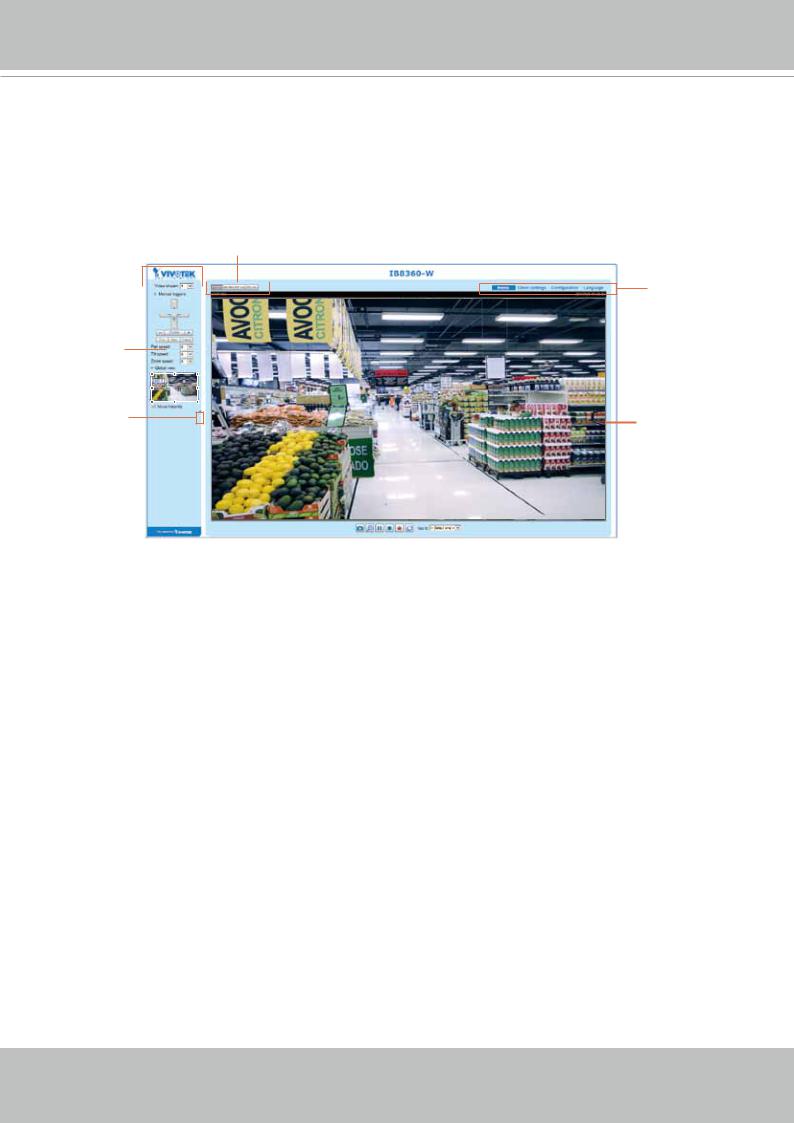
Main Page
This chapter explains the layout of the main page. It is composed of the following sections:
VIVOTEK INC. Logo, Host Name, Camera Control Area, Configuration Area, Menu, and Live
Video Window.
Resize Buttons
VIVOTEK INC.
Logo 

 Host Name Configuration
Area
Camera Control
Area
Hide Button |
Live View Window |
|
VIVOTEK INC. Logo
Click this logo to visit the VIVOTEK website.
Host Name
The host name can be customized to fit your needs. The name can be changed especially there are many cameras in your surveillance deployment. For more information, please refer to System on page 40.
Camera Control Area
Video Stream: This Network Camera supports multiple streams (streams 1 and 2) simultaneously. You can select any of them for live viewing. For more information about multiple streams, please refer to page 63 for detailed information.
Manual Trigger: Click to enable/disable an event trigger manually. Please configure an event setting on the Application page before you enable this function. A total of 3 event configuration can be configured.
For more information about event setting, please refer to page 108. If you want to hide this item on the homepage, please go to Configuration> System > Homepage Layout > General settings > Customized button to deselect the “show manual trigger button” checkbox.
User's Manual - 29
VIVOTEK
Configuration Area
Client Settings: Click this button to access the client setting page. For more information, please refer to Client Settings on page 34.
Configuration: Click this button to access the configuration page of the Network Camera. It is suggested that a password be applied to the Network Camera so that only the administrator can configure the
Network Camera. For more information, please refer to Configuration on page 39.
Language: Click this button to choose a language for the user interface. Language options are available in: English, Deutsch, Español, Français, Italiano, , Português, , , and Ρусский.
Please note that you can also change a language on the Configuration page; please refer to page 39.
Hide Button
You can click the hide button to hide or display the control panel.
Resize Buttons
 :
:
Click the Auto button, the video cell will resize automatically to fit the monitor.
Click 100% is to display the original homepage size.
Click 50% is to resize the homepage to 50% of its original size.
Click 25% is to resize the homepage to 25% of its original size.
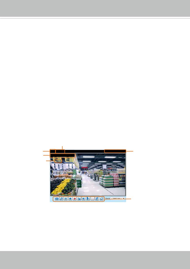
Live Video Window
■ The following window is displayed when the video mode is set to H.264:
H.264 Protocol and Media Options
Video Title |
Video (TPC-AV) |
2017/03/25 17:08:56 |
Time |
Title and Time |
Video 17:08:56 |
2017/03/25 |
|
Zoom Indicator |
x4.0 |
|
|
Video Control Buttons
Video Title: The video title can be configured. For more information, please refer to Video Settings on page 52.
H.264 Protocol and Media Options: The transmission protocol and media options for H.264 video streaming. For further configuration, please refer to Client Settings on page 34.
Time: Display the current time. For further configuration, please refer to Media > Image > Genral settings on page 52.
Title and Time: The video title and time can be stamped on the streaming video. For further configuration, please refer to Media > Image > General settings on page 57.
30 - User's Manual
Loading...