


VIVOTEK - A Leading Provider of Multimedia Communication Solutions
Table of Contents
Overview....................................................................................................................................................... |
3 |
Read before use...................................................................................................................................... |
3 |
Package contents.................................................................................................................................... |
3 |
Physical description................................................................................................................................. |
4 |
Installation .................................................................................................................................................... |
6 |
Hardware installation............................................................................................................................... |
6 |
Network deployment................................................................................................................................ |
8 |
Software installation .............................................................................................................................. |
11 |
Accessing the Network Camera ................................................................................................................. |
12 |
Using web browsers.............................................................................................................................. |
12 |
Using RTSP players .............................................................................................................................. |
14 |
Using 3GPP-compatible mobile devices ............................................................................................... |
15 |
Using VIVOTEK recording software...................................................................................................... |
16 |
Main Page .................................................................................................................................................. |
17 |
Client Settings ............................................................................................................................................ |
20 |
Configuration .............................................................................................................................................. |
22 |
System .................................................................................................................................................. |
22 |
Security ................................................................................................................................................. |
24 |
HTTPS................................................................................................................................................... |
25 |
Network ................................................................................................................................................. |
28 |
DDNS .................................................................................................................................................... |
36 |
Access list ............................................................................................................................................. |
38 |
Audio and video..................................................................................................................................... |
39 |
Motion detection.................................................................................................................................... |
45 |
Camera control...................................................................................................................................... |
47 |
Application............................................................................................................................................. |
50 |
Recording.............................................................................................................................................. |
57 |
System log............................................................................................................................................. |
59 |
View parameters ................................................................................................................................... |
60 |
Maintenance.......................................................................................................................................... |
61 |
Appendix .................................................................................................................................................... |
65 |
URL Commands of the Network Camera.............................................................................................. |
65 |
Technical Specifications ........................................................................................................................ |
93 |
Technology License Notice.................................................................................................................... |
94 |
Electromagnetic Compatibility (EMC).................................................................................................... |
95 |
2 - User's Manual

VIVOTEK - A Leading Provider of Multimedia Communication Solutions
Overview
VIVOTEK’s outdoor day/night network camera IP7142 is equipped with a wide dynamic range CMOS sensor to cope with any challenging lighting conditions.
Designed for outdoor 24-hour surveillance, IP7142 features the basics of day and night and vandal-proof functions that users can easily build up a cost-effective IP surveillance system without additional accessories. With a removable IR-cut filter and built-in IR illuminators, up to 15m, it can automatically remove the filter and turn on the IR illuminators during the nighttime to accept IR illumination for low light sensitivity. Meanwhile, the IP66-rated integrated housing shields this camera from dust and water, allowing it to be applied in harsh weather conditions of outdoor environments.
IP7142 with WDR (Wide dynamic range) feature can be very helpful to cope with very challenging lighting conditions. It is capable of capturing both of the dark part and bright part and combining the differences into a scene to generate a highly realistic image as the original scene. Because it preserves as much information in the video as possible, IP7142 helps provide video quality closer to the capabilities of the human eye. Consequently, it is largely applied in highly contrast environments such as lobby entrances, parking lots, ATM, loading areas and much more.
Incorporating numbers of advanced features including simultaneous dual streams, 3GPP mobile surveillance, 802.3af compliant PoE, two-way audio by SIP protocol, RS-485 interface for scanners or pan/tilts driver connection, and HTTPS encrypted data transmission, VIVOTEK IP7142 allows users to boost your robust IP surveillance system by reproducing clear images in proper color in extreme high-contrast environments for your indoor/outdoor security and monitoring applications.
Read before use
The use of surveillance devices may be prohibited by law in your country. The Network Camera is not only a high-performance web-ready camera but also can be part of a flexible surveillance system. It is the user’s responsibility to ensure that the operation of such devices is legal before installing this unit for its intended use.
It is important to first verify that all contents received are complete according to the Package contents listed below. Take notice of the warnings in Quick Installation Guide before the Network Camera is installed; then carefully read and follow the instructions in the Installation chapter to avoid damages due to faulty assembly and installation. This also ensures the product is used properly as intended.
The Network Camera is a network device and its use should be straightforward for those who have basic network knowledge. It is designed for various applications including video sharing, general security/surveillance, etc. The Configuration chapter suggests ways to best utilize the Network Camera and ensure proper operations. For the creative and professional developers, the URL Commands of the Network Camera section serves to be a helpful reference to customize existing homepages or integrating with the current web server.
Package contents
■IP7142
■Sun Shield
■Screws
■Camera stand
■Power adapter
■Silica gel
■RJ45 female/female coupler
■Quick installation guide
■Warranty card
■Software CD
User's Manual - 3
VIVOTEK - A Leading Provider of Multimedia Communication Solutions
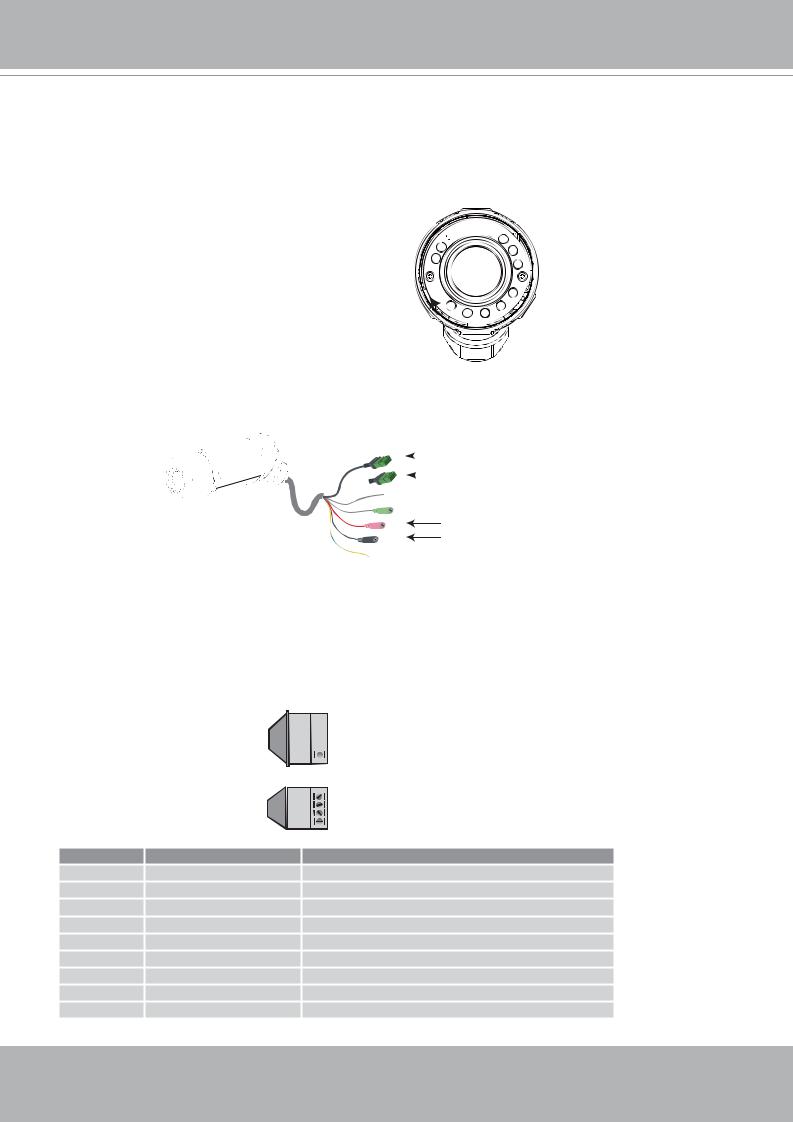
Physical description
Front panel
Light sensor 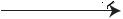


Lens 
IR LED 


Connectors
 General I/O terminal block


 Ethernet 10/100 RJ45 plug
 Audio out (green)
Microphone in (pink)
Power cord socket (black)
 Earth
Earth
General I/O Terminal Block
This Network Camera provides a general I/O terminal block which is used to connect external input / output devices. The pin definitions are described below.
N.C. 
 485B
485B 
 485A
485A 
 AC24V
AC24V 
 AC24V
AC24V 
N
2V
N.C.: No Connector
485B: RS485-
485A: RS485+
AC24V: Power in AC 24V
AC24V: Power in AC 24V
GND: Ground
DI : Digital Input
DO : Digital Output
+12V : Power, 12V DC
Pin |
Name |
Specification |
N.C. |
No Connector |
|
485B |
RS485- |
3.3V |
485A |
RS485+ |
3.3V |
AC24V |
Power in AC 24V |
AC 24V ± 5% |
AC24V |
Power in AC 24V |
AC 24V ± 5% |
GND |
Ground |
|
DI |
Digital Iutput |
OPEN/Short-to-GND, isolation 2kV |
DO |
Digital Output |
Max. 40VDC, max. 400mA, isolation 2kV |
+12V |
Power +12V |
12VDC ± 10%, max. 0.4A |
4 - User's Manual
VIVOTEK - A Leading Provider of Multimedia Communication Solutions
DI/DO Diagram
Refer to the following illustration for connection method.
12V
PIN 1
Power+12V
PIN 2
Digital output
+12V
PIN 3
Digital input
PIN 4
Ground
Status LED
The LED indicates the status of the Network Camera.
Status LED |
|
Description |
|
Blinking red (two short, one long) |
1. |
Power is being supplied to the Network Camera |
|
2. |
Restore, or reboot the Network Camera |
||
|
User's Manual - 5
VIVOTEK - A Leading Provider of Multimedia Communication Solutions
Hardware Reset


 Reset button

 Status LED
There is a reset button on the inner side of the Network Camera. It is used to reboot the Network Camera or restore the Network Camera to factory default. Sometimes rebooting the Network Camera could set the Network Camera back to normal state. If the problems remain after rebooted, restore the Network Camera to factory default and install again.
Reboot: Press and release the reset button. The status LED will blinks two short one long in red.
Restore: Press the reset button continuously for over 5 seconds until the status LED blinks two short one long in red. Note that all settings will be restored to factory default.
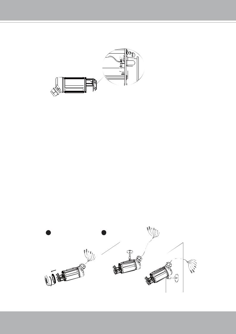
Installation
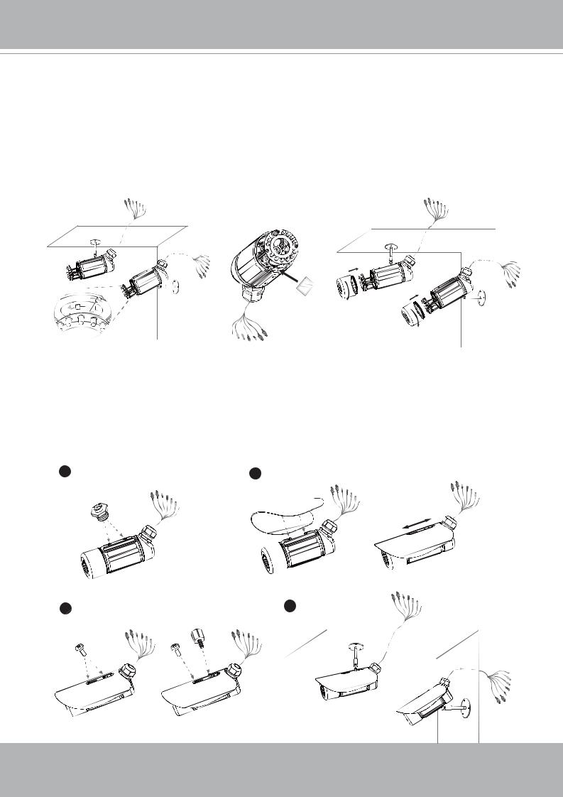
Hardware installation
Follow the steps below to install the Network Camera:
1.Open the lens cover.
2.Secure the Network Camera to the wall/ceiling by the supplied camera stand.
1 |
2 |
|
|
|
|
|
|
|
|
|
|
|
|
|
|
3.Feed power to the Network Camera and connect it to the Internet. For more information, please refer to Network deployment on page 8 for details.
6 - User's Manual
VIVOTEK - A Leading Provider of Multimedia Communication Solutions
4.Install the “Installation Wizard 2“ to assign IP address to the Network Camera. For more information, please refer to Software installation on page 11 for details.
5.Access to the Network Camera from the Internet. For more information, please refer to Accessing the Network Camera on page 12 for details.
6.Unscrew the zoom controller to adjust the zoom factor. Upon completion, tighten the zoom controller. Unscrew the focus controller to adjust the focus range. Upon completion, tighten the focus controller.
7.Put the supplied silica gel into the Network Camera and tighten the lens cover.
(Please replace the silica gel with a new one if you open the lens cover after installation.)
N
N
ili a gel

 ∞
∞
 ∞
∞
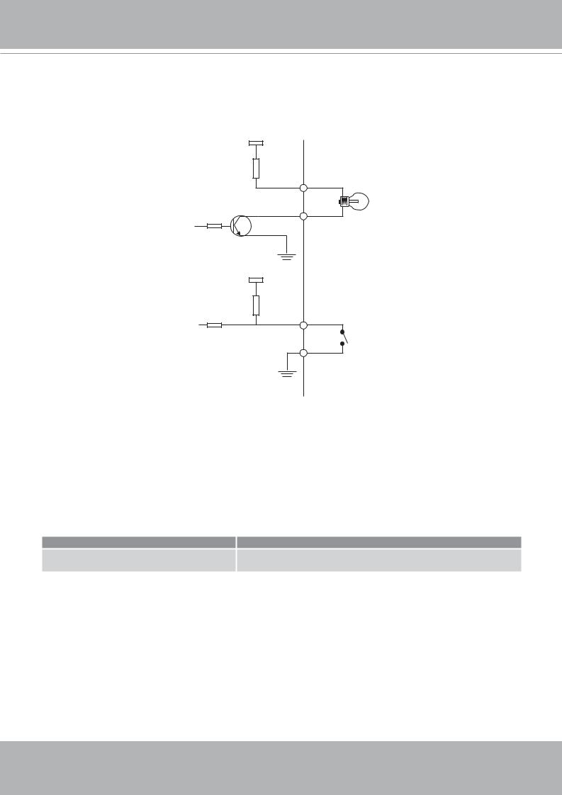
Note
If you want to use the supplied sun sheild for outdoor environments, please follow the steps below to install:
1.Tighten the supplied two screws.
2.Attach the supplied sun shield to the Network Camera and slide it to the desired position.
3.Fix the sun shield with supplied two screws. (Please use different screws for ceiling mount.)
1 |
|
|
2 |
|
4 |
|
|
3 |
|
|
|
|
|
|
|
|
|
|
|
|
|
|
|
Wall mount |
|
Ceiling mount |
|
|
|
User's Manual - 7
VIVOTEK - A Leading Provider of Multimedia Communication Solutions
Network deployment
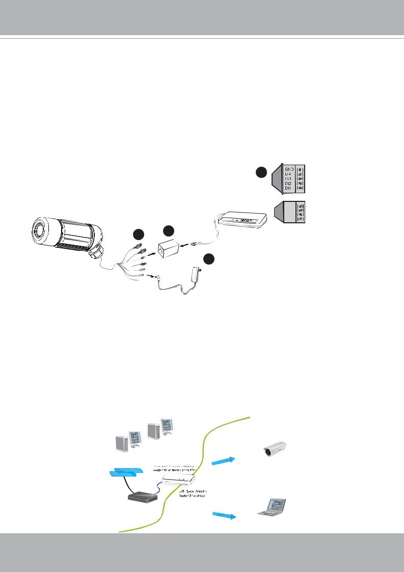
Setup the Network Camera over the Internet
This section explains how to configure the Network Camera to Internet connection.
1.If you have external devices such as sensors and alarms, make connection from general I/O terminal block.
2.Use the supplied RJ45 female/female coupler to connect the Network Camera to a switch. Use Catagory 5 Cross Cable when Network Camera is directly connected to PC.
3.Connect the power cable from the Network Camera to a power outlet.
1 |
N.C.: No Connector |
485B: RS485- |
|
|
485A: RS485+ |
|
AC24V: Power in AC 24V |
|
AC24V: Power in AC 24V |
GND: Ground
DI : Digital Input
DO : Digital Output
12
+12V : Power, 12V DC
1 |
2 |
|
|
Ethernet switch |
|||
|
|||
|
|
||
|
3 |
|
There are several ways to setup the Network Camera over the Internet. The first way is to setup the Network Camera behind a router. The second way is to utilize a static IP. The third way is to use PPPoE.
Internet connection via a router
Before setting up the Network Camera over the Internet, make sure you have a router and follow the steps below.
1.Connect your Network Camera behind a router, the Internet environment is illustrated as below. About how to get your IP address, please refer to Software installation on page 10 for details.
Internet
IP address : 192.168.0.3
WAN (Wide Area Network )
Subnet mask : 255.255.255.0 Default router : 192.168.0.1
Network)
: 192.168.0.1
Cable or DSL Modem
IP address : 192.168.0.2
Subnet mask : 255.255.255.0
Default router : 192.168.0.1
8 - User's Manual
VIVOTEK - A Leading Provider of Multimedia Communication Solutions
2.In this case, if the Local Area Network (LAN) IP address of your Network Camera is 192.168.0.3, please forward the following ports for the Network Camera on the router.
■HTTP port
■RTSP port
■RTP port for audio
■RTCP port for audio
■RTP port for video
■RTCP port for video
If you have changed the port numbers on the Network page, please open the ports accordingly on your router. For information on how to forward ports on the router, please refer to the user’s manual of your router.
3.Find out the public IP address of your router provided by your ISP (Internet Service Provider). Use the public IP and the secondary HTTP port to access the Network Camera from the Internet. Please refer to Network Type on page 28 for details.
Internet connection with static IP
Choose this connection type if you are required to use a static IP for the Network Camera and follow the steps below.
1.Set up the Network Camera in a LAN. Please refer to Software installation on page 10 for details.
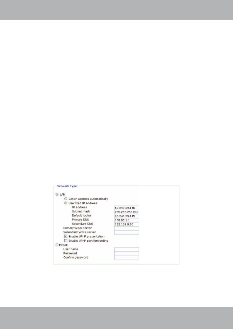
2.Go to Configuration > Network > Network Type. Select LAN > Use fixed IP address.
3.Enter the static IP, Subnet mask, Default router, Primary DNS provided by your ISP.
Internet connection via PPPoE (Point-to-Point over Ethernet)
Choose this connection type if you are connected to the Internet via a DSL Line. Please refer to PPPoE on page 29 for details.
User's Manual - 9
VIVOTEK - A Leading Provider of Multimedia Communication Solutions
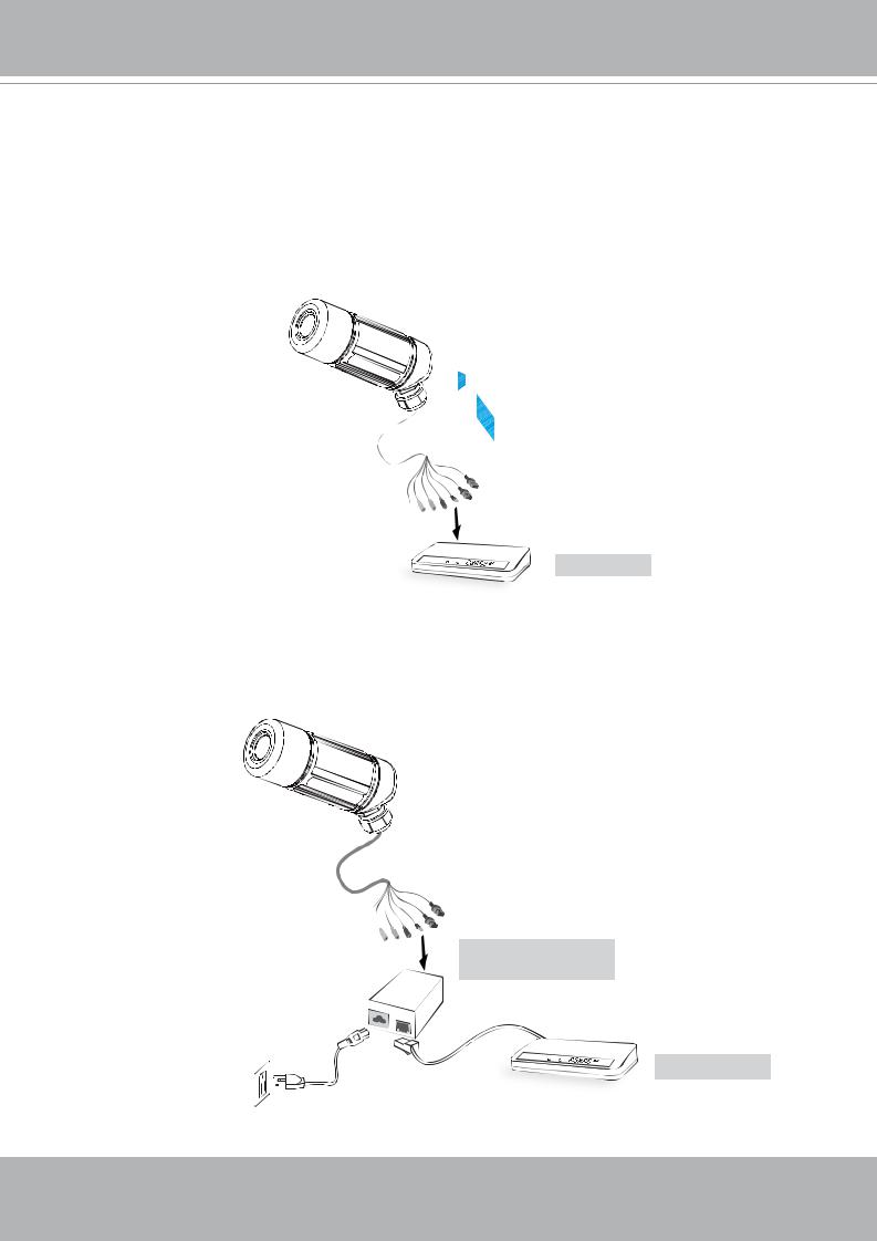
Set up the Network Camera through Power over Ethernet (PoE)
When using a PoE-enabled switch
The Network Camera is PoE-compliant, which allows it to be powered via a single Ethernet cable. If your switch/router supports PoE, refer to the following illustration to connect the Network Camera to a PoE-enabled switch/router via an Ethernet cable.
power + data transmission
PoE switch
When using a non-PoE switch
If your switch/router does not support PoE, use a PoE power injector (optional) to connect between the Network Camera and a non-PoE switch/router.
PoE power injector (optional)
non-PoE switch
10 - User's Manual
VIVOTEK - A Leading Provider of Multimedia Communication Solutions
Software installation
Installation Wizard 2 (IW2), free-bundled software packaged in the product CD, helps to set up your Network Camera in a LAN.
1. Install the IW2 under the Software Utility directory from the software CD. Double click the IW2 shortcut on your desktop to launch the program.
2.The program will conduct analyses on your network environment.
After your network environment is analyzed, please click Next to continue the program.
3.The program will search all VIVOTEK devices in the same LAN.
4.After searching, the main installer window will pop up. Click on the MAC and model name which match the product label on your device to connect to the Network Camera.
1
2
2D1 142 D
odel No |
IP 142 |
|
|
|
|
|||
|
|
|
|
|||||
|
|
|
|
|
|
|
2D1 142 D |
|
P N |
1 |
|
43 |
G |
|
|
|
|
N |
4 |
12123 |
1 |
|
|
|
|
|
t |
1 |
P |
|
|
|
|
|
|
N |
|
2D1 |
142 D |
|
||||
|
Ver |
1 |
G |
|
|
|
|
|
|
N |
|
N |
/ |
1 |
|
|
|
|
D |
IN |
I |
N |
|
|||
User's Manual - 11

VIVOTEK - A Leading Provider of Multimedia Communication Solutions
Accessing the Network Camera
This chapter explains how to access the Network Camera through web browsers, RTSP players, 3GPP-compatible mobile devices, and VIVOTEK recording software.
Using web browsers
1.Launch your web browser (ex. Microsoft® Internet Explorer, Mozilla Firefox or Netscape).
2.Enter the IP address of the Network Camera in the address field. Press Enter.
3.The live video will be displayed in your web browser.
http://192.168.5.132/index.html
Network Camera
NOTE
►For Mozilla Firefox or Netscape users, your browser will use Quick Time to stream the live video.
http://192.168.5.132/index.html http://192.168.5.132/index.html
Network Camera |
|
Network Camera |
12 - User's Manual
VIVOTEK - A Leading Provider of Multimedia Communication Solutions
►By default, the Network Camera is not password-protected. To prevent unauthorized accesses, it is highly recommended to set a password for the Network Camera.
For more information about how to enable password protection, please refer to Security on page 24.
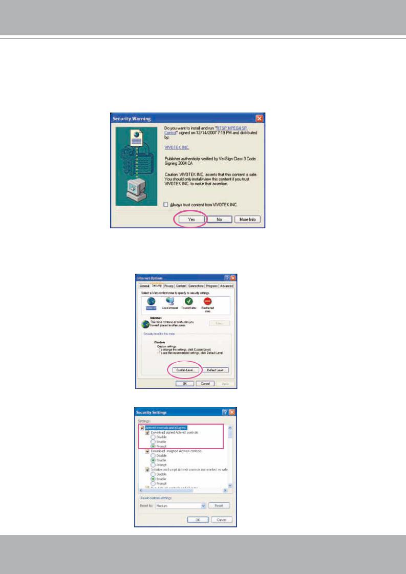
►If you see a warning message at initial access, click Yes to install an ActiveX® control on your computer.
►If you see a dialog box indicating that your security settings prohibit running ActiveX® Controls, please enable your ActiveX® Controls for your browser.
1. Choose Tools > Internet Options > Security > Custom Level.
2. Look for Download signed ActiveX® controls; select Enable or Prompt. Click OK.
User's Manual - 13

VIVOTEK - A Leading Provider of Multimedia Communication Solutions
Using RTSP players
To view the MPEG-4 streaming media using RTSP players, you can use one of the following players that support RTSP streaming.
Quick Time Player
Real Player
VLC media player
mpegable Player
pvPlayer
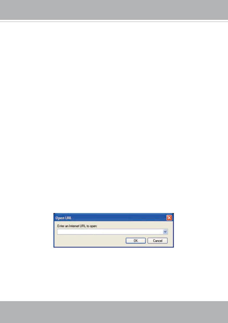
1.Launch a RTSP player.
2.Choose File > Open URL. An URL dialog box will pop up.
3.Type the URL command in the text box.
The format is rtsp://<ip address>:<rtsp port>/<access name for stream1 or stream2> For example:
rtsp://192.168.5.132:554/live.sdp
4. The live video will be displayed in your player.
For more information on how to configure RTSP access name, please refer to RTSP Streaming on page 34 for details.
14 - User's Manual
VIVOTEK - A Leading Provider of Multimedia Communication Solutions
Using 3GPP-compatible mobile devices
To view the streaming media through 3GPP-compatible mobile devices, make sure the Network Camera can be accessed from the Internet. For more information on how to set up the Network Camera over the Internet, please refer to Setup the Network Camera over the Internet on page 8.
To utilize this feature, please check the following settings on your Network Camera:
1.Because most players on 3GPP mobile phones do not support RTSP authentication, make sure the authentication mode of RTSP streaming is set to disable.
For more information, please refer to RTSP Streaming on page 34.
2.As the 3G network bandwidth is limited, you can’t use large video size. Please set the video and audio streaming parameters as listed below.
For more information, please refer to Audio and video on page 39.
Video |
|
ode |
|
P |
G 4 |
ra e |
i e |
|
1 |
144 |
|
a i |
u |
ra |
e rate |
p |
|
Intra |
ra |
e period |
1 |
|
|
Video |
ualit |
on tant it rate |
4 |
p |
|
udio t pe G |
|
12 2 |
p |
||
|
|
|
|
|
|
3.As most ISP and players only support port number 554 to allow RTSP streaming to go through, please set the RTSP port to 554.For more information, please refer to RTSP Streaming on page 34.
4.Launch the players on 3GPP-compatible mobile devices, (ex. Real Player). Type the URL commands in the player.
The format is rtsp://<public ip address of your camera>:<rtsp port>/<access name for stream1 or stream2>.
For example:
rtsp://192.168.5.132:554/live.sdp
User's Manual - 15
VIVOTEK - A Leading Provider of Multimedia Communication Solutions
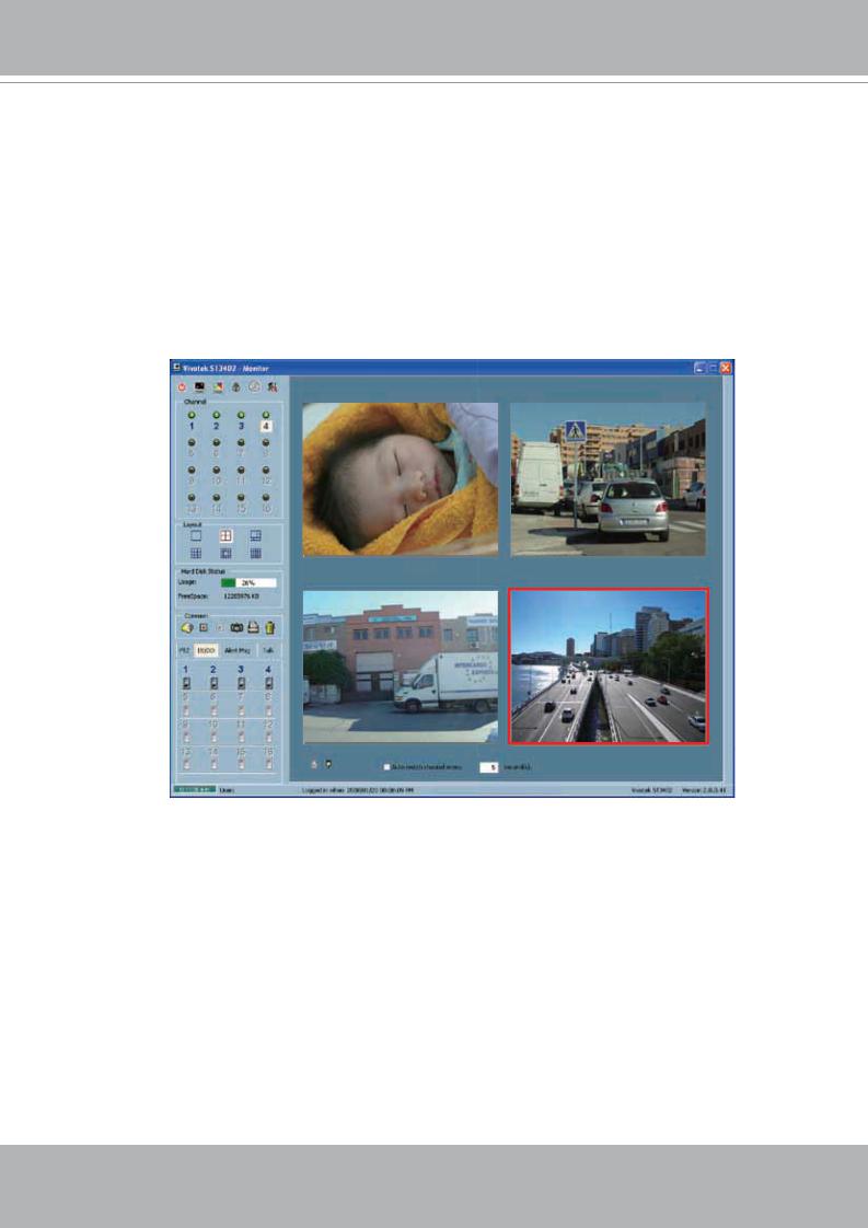
Using VIVOTEK recording software
The product software CD also contains recording software, allowing simultaneous monitoring and video recording for multiple Network Cameras. Please install the recording software; then launch the program to add the Network Camera to the Channel list. For detailed information about how to use the recording software, please refer to the user’s manual of the software or download it at http://www.vivotek.com.
16 - User's Manual
VIVOTEK - A Leading Provider of Multimedia Communication Solutions
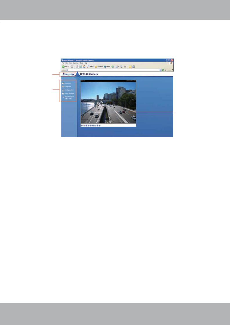
Main Page
This chapter explains the layout of the main page. It is composed of the following four sections: Logo of VIVOTEK INC., Menu, Host Name, and Live Video Window.
ogo o VIV |
IN |
http://192.168.5.132/index.html
|
|
|
o t na e |
Network Camera |
|
|
|
|
|
|
|
enu
i e iew window
Logo of VIVOTEK INC.
Click this logo to visit VIVOTEK website.
Menu
Snapshot: Click this button to capture and save still images. The captured images will be displayed in a pop-up window. Right-click the image and choose Save Picture As to save it in JPEG (*.jpg) or BMP (*.bmp) format.
Language: Click this button to choose a language for the displayed interface. Language options are available in: English, Deutsch, Español, Français, Italiano, , Português, and .
Configuration: Click this button to access the configuration page of Network Camera. It is suggested that a password is applied to the Network Camera so that only the administrator can configure the Network Camera. For more information, please refer to Configuration on page 22.
Client Settings: Click this button to access the client setting page. For more information, please refer to Client Settings on page 20.
Digital Output: Click this button to turn on or off the digital output device.
Host Name
The host name can be customized to fit your needs. For more information, please refer to System on page 22.
User's Manual - 17
VIVOTEK - A Leading Provider of Multimedia Communication Solutions
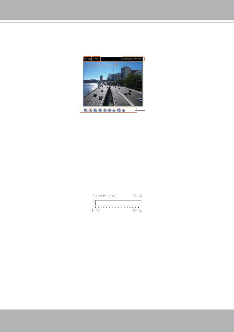
Live Video Window
The following window is displayed when the video mode is set to MPEG-4:
Video title itle and ti e
P G 4 proto ol and edia option
|
IP 142 |
P |
V |
|
|
|
|
|
i e |
|
|
|
|
|
|
|
|
||||
|
|
|
|
|
|
|
|
|
|
|
|
IP |
142 1 |
3 |
1 2 |
1 |
3 |
|
|
|
|
|
|
|
|
|
|
|
|
|
|
|
Video and audio ontrol utton
Video title: The video title can be configured. For more information, please refer to Video settings on page 39.
Time: Display the current time. For more information, please refer to Video settings on page 39.
Title and time: Video title and time can be stamped on the streaming video. For more information, please refer to Video settings on page 39.
MPEG-4 protocol and media options: The transmission protocol and media options for MPEG-4 video streaming. For more information, please refer to Client Settings on page 20.
Video and audio control buttons: Depending on the Network Camera model and Network Camera configuration, some buttons may not be available.
 Digital zoom edit: Deselect Disable digital zoom to enable the zoom operation. The navigation screen indicates which part of the image is being magnified. To control the zoom level, drag the slider bar. To move to a different area you want to magnify, drag the navigation screen.
 Start MP4 recording: Click this button to record video clips in MP4 file format to your computer. Press the
  Stop MP4 recording button to end recording. When you quit the web browser, video recording stops accordingly. To specify the storage destination and the file name, please refer to MP4 Saving Options on page 21 for details.
 Talk: Click this button to talk to people around the Network Camera. Audio will come out from the external speaker connected to the Network Camera.
 Pause: Pause the transmission of streaming media. The button becomes
  Resume button after clicking the Pause button.
 Resume: Resume the transmission of streaming media. The button becomes
  Pause button after clicking the Resume button.
 Stop: Stop the transmission of streaming media. Click the
  Resume button to continue transmission.
 Volume: When the
  mute function is not activated, move the slider bar to adjust the volume at local computer.
18 - User's Manual

VIVOTEK - A Leading Provider of Multimedia Communication Solutions
 Mute: Turn off the
  volume at local computer.
 Mic Volume: When the
  mute function is not activated, move the slider bar to adjust the microphone volume at local computer.
 Mute: Turn off the
  microphone volume at local computer.
The following window is displayed when the video mode is set to MJPEG:
Video title itle and ti e
IP 142
G 1 11 2 1
i e
Video ontrol utton
Video title: The video title can be configured. For more information, please refer to Video settings on page 39.
Time: Display the current time. For more information, please refer to Video settings on page 39.
Title and time: Video title and time can be stamped on the streaming video. For more information, please refer to Video settings on page 39.
Video and audio control buttons: Depending on the Network Camera model and Network Camera configuration, some buttons may not be available.
 Digital zoom edit: Deselect Disable digital zoom to enable the zoom operation. The navigation screen indicates which part of the image is being magnified. To control the zoom level, drag the slider bar. To move to a different area you want to magnify, drag the navigation screen.
 Start MP4 recording: Click this button to record video clips in MP4 file format to your computer. Press the
  Stop MP4 recording button to end recording. When you quit the web browser, video recording stops accordingly. To specify the storage destination and the file name, please refer to MP4 Saving Options on page 21 for details.
 Talk: Click this button to talk to people around the Network Camera. Audio will come out from the external speaker connected to the Network Camera.
 Mic Volume: When the
  mute function is not activated, move the slider bar to adjust the microphone volume at local computer.
 Mute: Turn off the
  microphone volume at local computer.
User's Manual - 19
VIVOTEK - A Leading Provider of Multimedia Communication Solutions
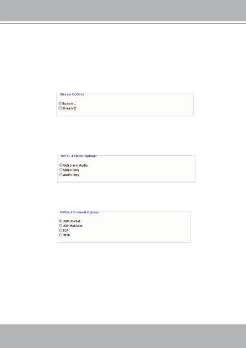
Client Settings
This chapter explains how to select the streaming source, transmission mode and saving options at local computer. It is composed of the following four sections: Stream Options, MPEG-4 Media Options, MPEG-4 Protocol Options and MP4 Saving Options. When completed with the settings on this page, click Save on the page bottom to take effect.
Stream Options
The Network Camera supports MPEG-4 and MJPEG dual streams. For more information, please refer to Video settings on page 39.
MPEG-4 Media Options
Select to stream video or audio data. This works only when the video mode is set to MPEG-4.
MPEG-4 Protocol Options
Depending on your network environment, there are four transmission modes of MPEG-4 streaming:
UDP unicast: This protocol allows for more real-time audio and video streams. However, network packets may be lost due to network burst traffic and images may be broken. Activate UDP connection when occasions require time-sensitive responses and the video quality is less important. Note that each unicast client connecting to the server takes up additional bandwidth and the Network Camera allows up to ten simultaneous accesses.
UDP multicast: This protocol allows multicast-enabled routers to forward network packets to all clients requesting streaming media. This helps to reduce the network transmission load of the Network Camera while serving multiple clients at the same time. Note that to utilize this feature, the Network Camera must be configured to enable multicast streaming at the same time. For more information, see RTSP Streaming on page 34.
20 - User's Manual
VIVOTEK - A Leading Provider of Multimedia Communication Solutions
TCP: This protocol guarantees the complete delivery of streaming data and thus provides better video quality. Nevertheless, the downside with this protocol is that its real-time effect is not as good as that of the UDP protocol.
HTTP: This protocol allows the same quality as TCP protocol and you don’t need to open specific port for streaming under some network environments. Users inside a firewall can utilize this protocol to allow streaming data to come through.
MP4 Saving Options
Users can record the live video as they are watching it by clicking  Start MP4 Recording on the main page. Here, you can specify the storage destination and file name.
Folder: Specify a storage destination for the recorded video files.
File Name Prefix: Enter the text that will be put in front of the video file name.
Add date and time suffix to the file name: Select this option to add date and time to the file name suffix.
CLIP_200801008-180853
File name prefix Date and time suffix e r t is:
User's Manual - 21
VIVOTEK - A Leading Provider of Multimedia Communication Solutions
Configuration
Only Administrators can access the system configuration page. Each category in the left menu will be explained in the following sections.
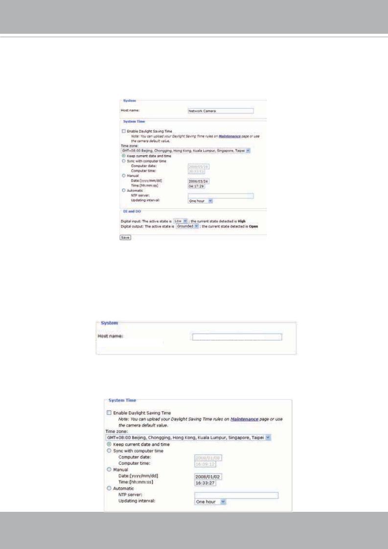
System
This section explains how to configure the basic settings for the Network Camera, such as the host name and system time. It is composed of the following three columns: System, System Time and DI and DO. When completed with the settings on this page, click Save on the page bottom to take effect.
System
et me
Host name: Set a desired name for the Network Camera. The text will be displayed at the top of the main page.
System Time
22 - User's Manual
VIVOTEK - A Leading Provider of Multimedia Communication Solutions
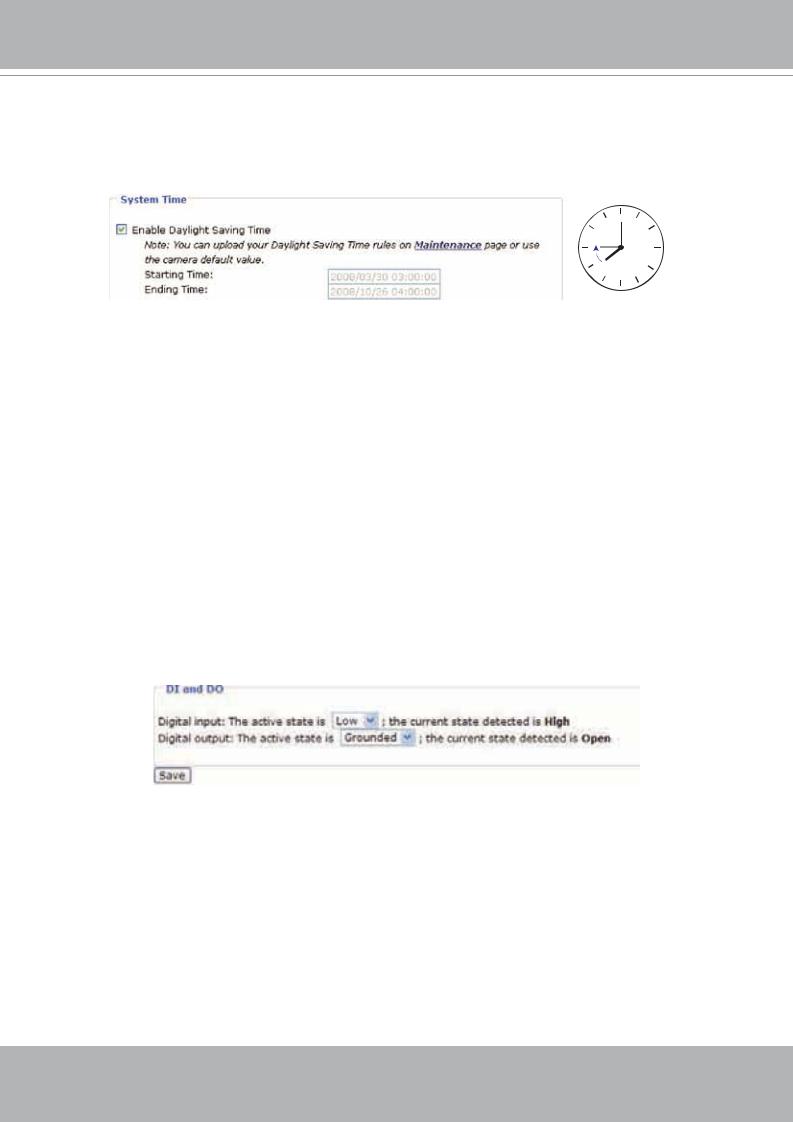
Enable Daylight Saving Time: Select this option to enable daylight saving time (DST). During DST, the system clock moves one hour ahead. Note that to utilize this feature, please set the time zone for your Network Camera first. Then, the starting time and ending time of the DST is displayed upon selecting this option. To manually configure the daylight saving time rules, please refer to Upload / Export Daylight Saving Time Configuration File on page 62 for details.
Time zone: According to your local time zone, select one from the drop-down list.
Keep current date and time: Select this option to reserve the current date and time of the Network Camera. The Network Camera’s internal real-time clock maintains the date and time even when the power of the system is turned off.
Sync with computer time: Select this option to synchronize the date and time of the Network Camera with the local computer. The read-only date and time of the PC is displayed as updated.
Manual: The administrator can enter the date and time manually. Note that the date and time format are [yyyy/mm/dd] and [hh:mm:ss].
Automatic: The Network Time Protocol is a protocol serves synchronize computer clocks by periodically querying an NTP Server.
NTP server: Assign the IP address or domain name of the time-server. Leaving the text box blank connects the Network Camera to the default time-servers.
Update interval: Select to update the time with the NTP server on hourly, daily, weekly, or monthly basis.
DI and DO
Digital input: Select High or Low to define normal status of the digital input. The Network Camera will report the current status.
Digital output: Select Grounded or Open to define normal status of the digital output. The Network Camera will show whether the trigger is activated or not.
User's Manual - 23

VIVOTEK - A Leading Provider of Multimedia Communication Solutions
Security
This section explains how to enable password protection and create multiple accounts. It is composed of the following three columns: Root Password, Add User and Manage User.
Root Password
The administrator account “root” is permanent and can not be deleted. Please note that if you want to add more accounts, you must apply a password for the “root” account first.
1.Type the password identically in both text boxes.
2.Click Save to enable password protection.
3.A window will be prompted for authentication; type the correct user’s name and password in related fields to access the Network Camera.
Add User
Administrators can add up to twenty user accounts.
1.Input the new user’s name and password.
2.Select the desired security level. Click Add to take effect.
Access rights are sorted by user types. There are three kinds of user types. Only administrators can access the Configuration page. Operators and viewers can not access the configuration page. Though operators can not access the page, they are capable of using the url commands to get and set the value of parameters. For more information, please refer to URL Commands of the Network Camera on page 65. Viewers can only access the main page.
Manage User
Here you can change user’s access rights or delete user accounts.
1.Pull down the user list to find an account.
2.Make necessary changes and then click Save or Delete to take effect.
24 - User's Manual

VIVOTEK - A Leading Provider of Multimedia Communication Solutions
HTTPS
This section explains how to enable authentication and encrypted communication over SSL.
Enable HTTPS
Select this option to turn on the HTTPS communication.
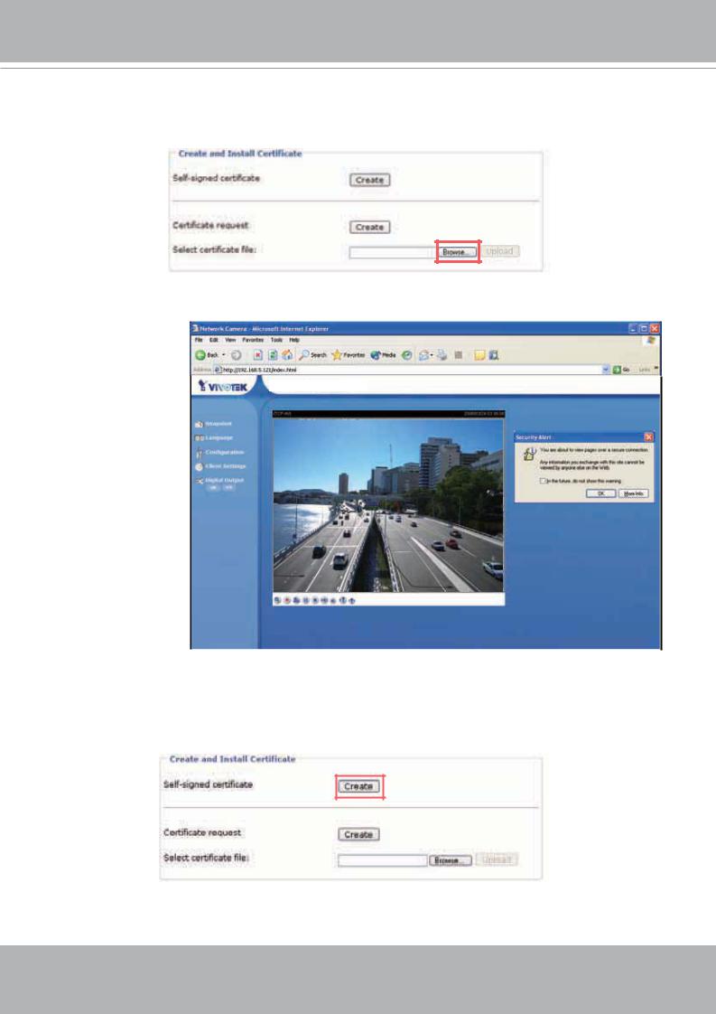
Create and Install Certificate
Select either to create a self-signed certificate or a signed certificate.
To create a certificate from a certificate authority
1. Click Create for Certificate request. The Create Certificate window will pop up.
2. Fill in the information required for generating a Certificate Signing Request (CSR) and click Save.
. . .
3. Here is an example of a CSR:
User's Manual - 25
VIVOTEK - A Leading Provider of Multimedia Communication Solutions
4.Look for a trusted certificate authority that issues digital certificates. Enroll the Network Camera. Wait for the certificate authority to issue a SSL certificate; then upload the issued certificate to the Network Camera.
5. Browsing the Network Camera using HTTPS helps to protect streaming data over the Internet.
ttp
|
|
http |
. |
. . |
inde .htm |
Network Camera
To create a self-signed certificate
1. Click Create for Create and Install Certificate. This pops up the Create Certificate window.
26 - User's Manual
VIVOTEK - A Leading Provider of Multimedia Communication Solutions
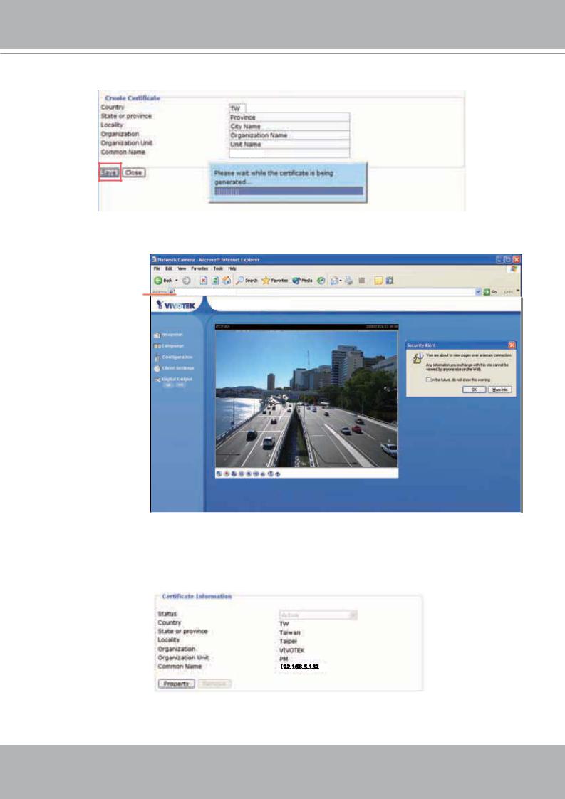
2. Fill in the information required for generating a Certificate Signing Request (CSR) and click Save.
192.168.5.132
3. Browsing the Network Camera using HTTPS helps to protect streaming data over the Internet.
ttp
http ://192.168.5.132/index.html
Network Camera
Certificate Information
Here display the certification information. Users may click Property for details. To remove the signed certificated, uncheck the Enable HTTPS secure connection and click Remove.
192.168.5.132
User's Manual - 27

VIVOTEK - A Leading Provider of Multimedia Communication Solutions
Network
This section explains how to configure wired network connection for the Network Camera. It is composed of the following five columns: Network Type, HTTP, Two way audio, FTP and RTSP Streaming. When completed with the settings on this page, click Save to take effect.
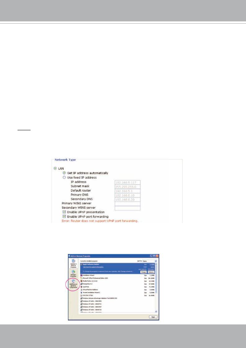
Network Type
LAN
Select this option when the Network Camera is deployed in a local area network (LAN) and is intended to be accessed by local computers.
Get IP address automatically: Select this option to obtain an available dynamic IP address assigned by a DHCP server each time the camera is connected to the LAN.
Use fixed IP address: Select this option to manually assign a static IP address to the Network Camera. Please refer to Internet connection with static IP on page 9 for details.
Enable UPnP presentation: Select this option to enable UPnPTM presentation for your Network Camera so that whenever a Network Camera is presented to the LAN, shortcuts of connected Network Cameras will be listed in My Network Places. Currently, UPnPTM is supported by Windows XP or later. Note that to utilize this feature, please make sure the UPnPTM component is installed on your computer.
http |
. |
. . |
inde .htm |
Network Camera
Networ a era 1 2 1 |
132 |
|
|
Enable UPnP port forwarding: To access the Network Camera from the Internet, select this option to allow the Network Camera to open ports on the router automatically so that video streams can be sent out from a LAN. To utilize of this feature, make sure that your router supports UPnPTM and it is activated.
28 - User's Manual
VIVOTEK - A Leading Provider of Multimedia Communication Solutions
PPPoE (Point-to-point over Ethernet)
Select this option to configure your Network Camera to make it accessible from anywhere as long as there is an Internet connection. Note that to utilize this feature, it requires an account provided by your ISP.
Follow the steps below to acquire your Network Camera’s public IP address.
1.Set up the Network Camera in a LAN.
2.Go to Configuration > Application > Server Settings (please refer to Server Settings on page 52) to add a new server -- email or FTP server.
3.Go to Configuration > Application > Media Settings (please refer to Media Settings on page 50). Select System log so that you will receive a list of system log in TXT file format which contains the Network Camera’s public IP address in your email or on the FTP server.
4.Go to Configuration > Network > Network Type. Select PPPoE and enter the user name and password provided by your ISP. Click Save to take effect.
5.The Network Camera starts to reboot.
6.Disconnect the power source of the Network Camera; remove it from the LAN environment to the Internet.
NOTE
►If the default ports are already used by other device connecting to the same router, the Network Camera will select other ports for the Network Camera.
►If UPnPTM is not supported by your router, you will see the following message.
►Steps to enable UPnPTM user interface on your computer:
Note that you must log on to the computer as a system administrator to install the UPnPTM components.
1.Go to Start, click Control Panel, and then click Add or Remove Programs.
User's Manual - 29
 Loading...