


 Loading...
CC8160 Compact Cube
Network Camera
User’s Manual
2MP • 180° Panoramic View • Smart Stream II •


 Rev.
Rev. 1.0
1.0


VIVOTEK
Table of Contents
Revision History 3
Overview 4
Read Before Use 5 Package Contents 5 Symbols and Statements in this Document 5 Physical Description 6 Hardware Installation 9
Network Deployment 12
Setting up the Network Camera over the Internet 12 Software Installation 14 Ready to Use 15
Accessing the Network Camera 16
Using Web Browsers 16 Using RTSP Players 19 Using 3GPP-compatible Mobile Devices 20 Using VIVOTEK Recording Software 21
Main Page 22
Client Settings 27
H.264 Media Options 27
H.264 Protocol Options 27 MP4 Saving Options 28 Local Streaming Buffer Time 28
Configuration32
System > General settings |
33 |
System > Homepage layout |
35 |
System > Logs |
38 |
System > Parameters |
40 |
System > Maintenance |
41 |
Media > Image |
45 |
Exposure 49
Media > Video |
53 |
Media > Video |
54 |
Media > Audio |
61 |
Network > General settings |
62 |
Network > Streaming protocols |
69 |
Application 77
Network > SNMP (Simple Network Management Protocol) |
78 |
Network > FTP |
79 |
Security > User accounts |
80 |
Security > HTTPS (Hypertext Transfer Protocol over SSL) |
81 |
2 - User's Manual

VIVOTEK
Security > Access List 88 PTZ > PTZ settings 93 Event > Event settings 97 Applications > Motion detection 111 Applications > Tampering detection 114 Applications > Audio detection 115 Applications > Package management - a.k.a., VADP (VIVOTEK Application Development Platform) 117 Recording > Recording settings 120
Appendix 125
URL Commands for the Network Camera 125 1. Overview 125 2. Style Convention 125 Technical Specifications 212 Technology License Notice 213 H.264 213 MPEG-4 AAC Technology 213 AMR-NB Standard 213 Electromagnetic Compatibility (EMC) 214
Revision History
Rev. 1.0: Initial release
User's Manual - 3

VIVOTEK
Overview
VIVOTEK’s CC8160 is a low profile network camera especially designed for 180° panoramic indoor surveillance. The unique design makes it a great choice for retail, convenience stores, hotels, classrooms, and offices. The 180° panoramic view in 1080P provides amazing situational surveillance coverage. The unique mounting design facilitates easy installation on a wall, or counter to capture faces at eye level. A built-in microphone further increases the level of surveillance while recording sound within a 5 meter radius.
The CC8160 supports industry-standard H.264 compression technology, reducing file sizes and conserving valuable network bandwidth. Together with the ST7501 multi-lingual 32-channel recording software, users can set up an easy-to-use IP surveillance system with ease.
Liability/ Disclaimer
Please inform your local VIVOTEK office of any inaccuracies or omissions. VIVOTEK cannot be held responsible for any technical or typographical errors and reserves the right to make changes to the product and manuals without prior notice. VIVOTEK makes no warranty of any kind with regard to the material contained within this document, including, but not limited to, the implied warranties of merchantability and fitness for a particular purpose. VIVOTEK shall not be liable nor responsible for incidental or consequential damages in connection with the furnishing, performance or use of this material. This product is only to be used for its intended purpose.
Intellectual Property Rights
VIVOTEK has intellectual property rights relating to technology embodied in the product described in this document. In particular, and without limitation, these intellectual property rights may include one or more of the patents or pending patent applications in the Taiwan, United Sates and other countries. This product contains licensed third-party software also. Please visit VIVOTEK website for more information.
Trademark Acknowledgments
The trademark "VIVOTEK" or any other trademarks, service marks, trade names, distinctive logos, pictures, or designs as designated by VIVOTEK and as used on or in connection with the Product are the sole properties of VIVOTEK ("VIVOTEK Trademarks and Trade Names").
VIVOTEK are registered trademarks or trademark applications in various jurisdictions. All other company names and products are trademarks or registered trademarks of their respective companies.
User hereby acknowledges and recognizes that any and all "VIVOTEK’s Trademarks and Trade
Names, patents, copyrights, know-how and other intellectual property rights” used or embodied in the Product are and shall remain the sole properties of VIVOTEK.
.
4 - User's Manual
VIVOTEK
Read Before Use
The use of surveillance devices may be prohibited by law in your country. The Network Camera is not only a high-performance web-ready camera but can also be part of a flexible surveillance system. It is the user’s responsibility to ensure that the operation of such devices is legal before installing this unit for its intended use.
It is important to first verify that all contents received are complete according to the Package Contents listed below. Take note of the warnings in the Quick Installation Guide before the Network Camera is installed; then carefully read and follow the instructions in the Installation chapter to avoid damage due to faulty assembly and installation. This also ensures the product is used properly as intended.
The Network Camera is a network device and its use should be straightforward for those who have basic networking knowledge. It is designed for various applications including video sharing, general security/ surveillance, etc. The Configuration chapter suggests ways to best utilize the Network Camera and ensure proper operations. For creative and professional developers, the URL Commands of the Network
Camera section serves as a helpful reference to customizing existing homepages or integrating with the current web server.
Package Contents
■ CC8160 - the Network Camera |
■ Quick Installation Guide / Warranty Card |
■ Screws |
|
Symbols and Statements in this Document
|
i |
|
INFORMATION: provides important messages or advices that might help prevent inconvenient |
||||
|
|
or problem situations. |
|||||
|
|
|
|
|
|
|
NOTE: Notices provide guidance or advices that are related to the functional integrity of the |
|
|
|
|
|
|
|
machine. |
|
|
|
|
|
|
|
Tips: Tips are useful information that helps enhance or facilitae an installation, function, or |
|
|
|
|
|
|
|
|
|
|
|
|
|
|
|
|
|
|
|
|
|
|
|
process. |
|
|
|
|
|
|
|
WARNING! or IMPORTANT!: These statements indicate situations that can be dangerous or |
|
|
|
|
|
|
|
hazardous to the machine or you. |
|
|
|
|
|
|
|
Electrical Hazard: This statement appears when high voltage electrical hazards might occur |
|
|
|
|
|
|
|
to an operator. |
User's Manual - 5
VIVOTEK
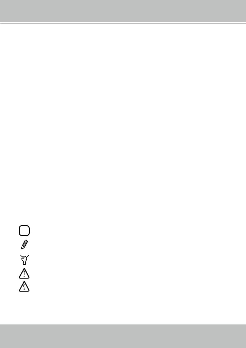
Physical Description
Reset button
Lens
Microphone
 LED
LED

 RJ-45 release hole
Camera bracket
6 - User's Manual
VIVOTEK
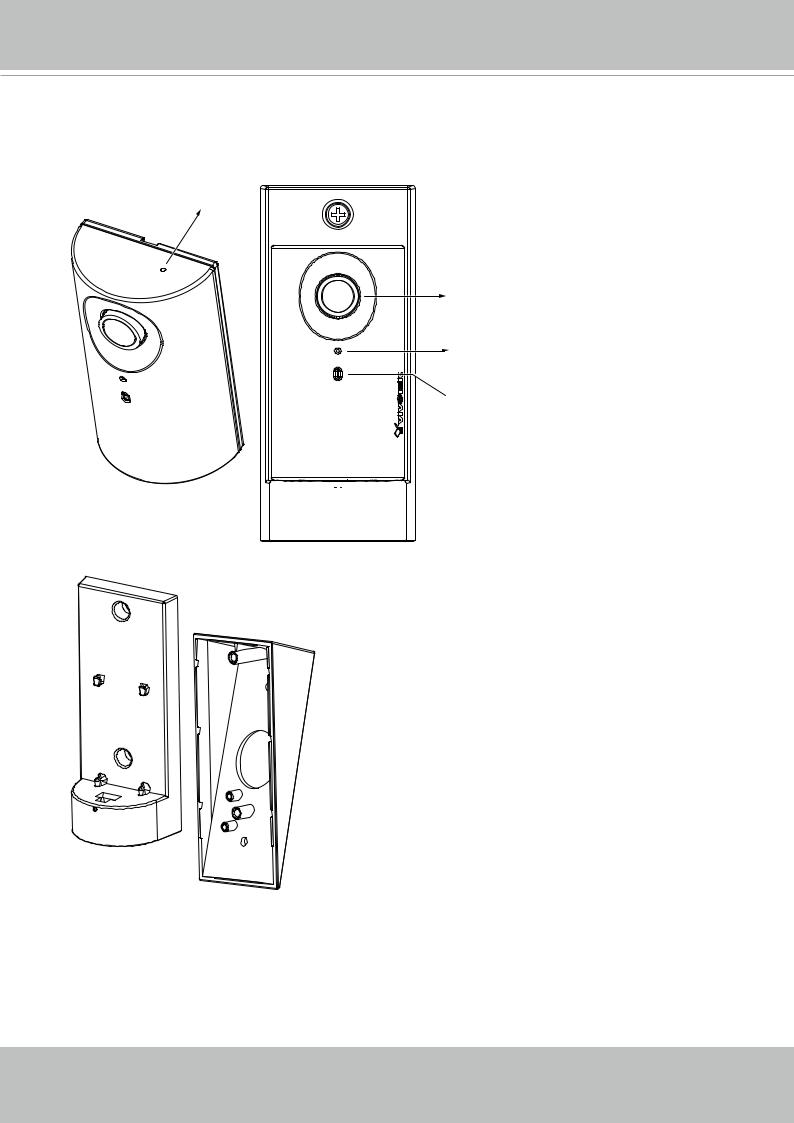
Considerations
Camera View Coverage
Side View
Vertical: |
Horizontal: |
|
100º |
||
180º |
||
|
Top View
Installation Concern


 15º
15º
1.6~1.8m
|
|
|
|
|
|
|
|
|
|
|
|
|
|
|
|
|
|
|
|
|
|
|
|
|
|
|
|
|
|
|
|
|
|
|
|
|
|
|
|
|
|
|
|
|
|
|
|
|
|
|
|
|
|
|
|
|
|
|
|
|
|
|
|
|
|
|
|
|
|
|
|
|
|
|
|
|
|
|
|
|
|
|
|
|
|
|
|
|
|
|
|
|
|
|
3m |
|
|
|
|
|
|
|
||
|
|
|
|
|
|
|
|
|
|
|||||
|
|
|
|
|
|
|
|
|
|
|
|
|
|
|
|
Recognition |
|
|
|
2m |
|
||||||||
|
|
|
|
|||||||||||
|
|
|
Perception |
|||||||||||
|
|
|
|
|
|
|
|
|
|
|
|
|||
|
|
|
|
|
|
|
|
|
|
|
||||
The camera is designed to capture human activities in a near-hemispheric field of view, at a place such as a cashier or bank counter. Due to the optical characteristics of wide-angle lens, image quality decreases as distance from an object increases. It is therefore recommended to install the camera within 3 meters or closer to the objects of your interest. The focus center should also be aligned with objects of importance, say, human faces.
User's Manual - 7
VIVOTEK
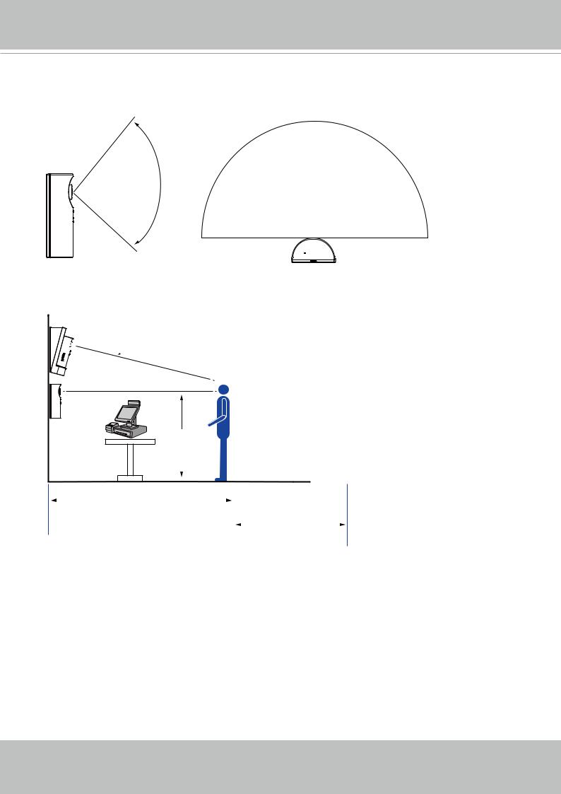
Reset Button
Hardware Reset
The reset button is used to reset the system or restore the factory default settings. Sometimes resetting the system can return the camera to normal operation. If the system problems remain after a reset, press the reset button longer to restore the factory settings and install again.
Reset: Press and release the recessed reset button with a straightened paper clip. Wait for the Network Camera to reboot.
Restore: Press and hold the recessed reset button for at least several seconds to restore. Note that all settings will be restored to factory defaults.
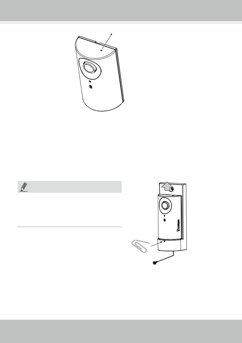
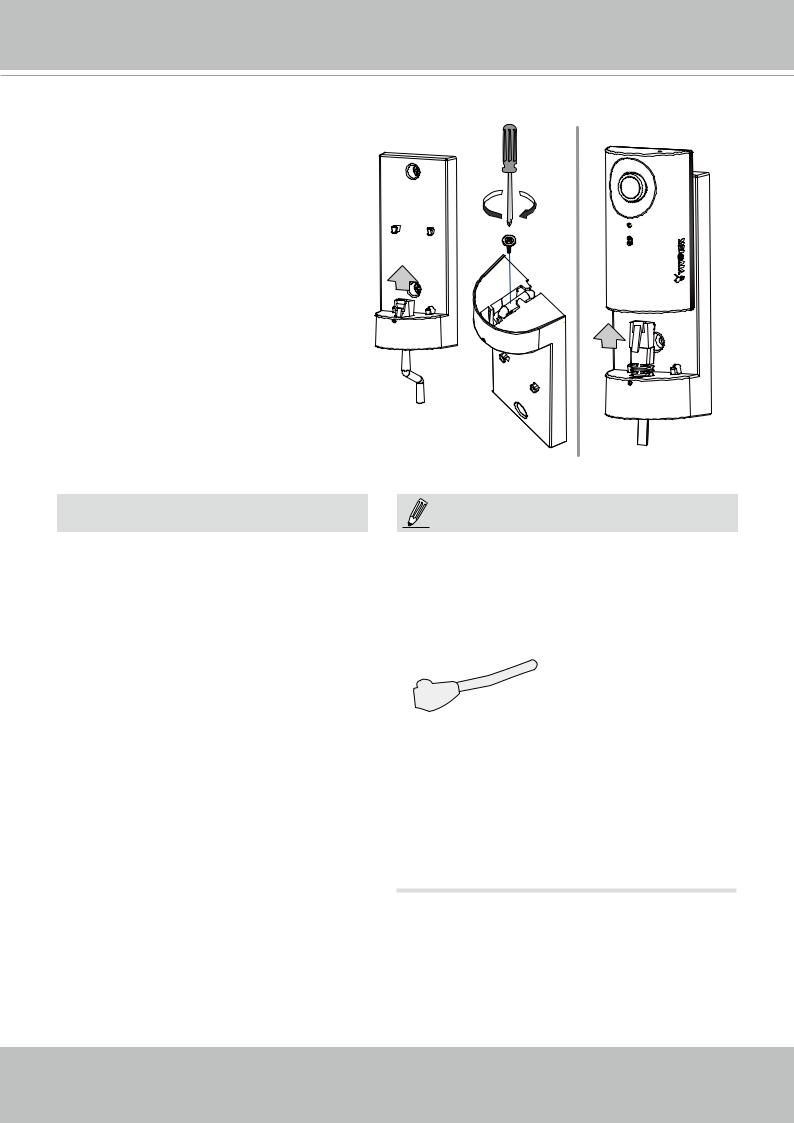
NOTE:
To detach a camera, remove the retention screw from the top and from the bottom, and insert a straightened paperclip into the release button to press on the RJ-45 locking tab.
8 - User's Manual
VIVOTEK
Hardware Installation
 Connecting Ethernet Cable
1. Insert your Ethernet cable through the opening at the bottom of the camera bracket.
2. If using a round cable: When the
RJ-45 plug is fully inserted, use the round-head screw with a washer to secure its position from the bottom of the bracket.
If using a flat cable: Pass the cable through the opening and attach to camera.
Round cable
Flat cable
 IMPORTANT:
Record the MAC address before installing the camera.
Network Camera
Model No: XXXXXX
MAC: 0002D1083236
This device complies with part 15 of the FCC Rules. Operation is subject to the following two conditions:
(1)this device may not cause harmful interference, and
(2)this device must accept any interference received, including interference that may cause undesired operation.
Pat. 6,930,709 |
Made in Taiwan |
|
|
NOTE:
It is recommended to use an Ethernet cable that comes without the strain relief boot. You can remove the boot if your cable comes with one.
Strain relief boot
User's Manual - 9

VIVOTEK
 Mounting the Network Camera - Wall Mount
1.You can install the camera to a vertical surface by driving screws through the holes shown below.
2.You may also install the bracket to a 4” x 2” utility box (as outlet or switch socket).
3.Another option is using the 15° tilt bracket so that the camera can be installed to an overlooking position. Attach the bracket to a utility box, and then secure the mount bracket. You can route the cable through the hole in the middle.
4.Attach a rubber seal pad to the bottom of the mount bracket.
5.Install the camera. Make sure the RJ-45 connector is properly connected.
1 |
2 |
3 |
4 |
5 |
10 - User's Manual
VIVOTEK
LED Definitions |
|
|
|
|
|
Item |
LED status |
Description |
1 |
Steady Red |
Power is on and system booting |
|
Red LED off |
Powered down |
2 |
Red blinks every 1 second. Network works (heartbeat). |
|
|
On for 1 second, and Off for Note that on this model, LED blinking may not be very |
|
|
another. |
discernible. |
|
Steady Red |
Network failed. |
3Blinks Red every 0.15 second. Upgrading firmware. On for 0.15 second, and Off for
another)
4Blinks Red every 0.15 second. Restoring defaults.
On for 0.15 second, and Off for another.
To detach a camera, remove the retention screw from the top and from the bottom, and insert a straightened paperclip into the release button to press on the RJ-45 locking tab.
2
1
User's Manual - 11

VIVOTEK
Network Deployment
Setting up the Network Camera over the Internet
There are several ways to set up the Network Camera over the Internet. The first way is to set up the Network Camera behind a router. The second way is to utilize a static IP. The third way is using PPPoE.
Internet connection via a router
Before enabling the access to the Network Camera over the Internet, make sure you have a router and follow the steps below.
1. Connect your Network Camera behind a router, the Internet environment is illustrated below.
Regarding how to obtain your IP address, please refer to Software Installation on page 14 for details.
WAN (Wide Area Network )
Router IP address : from ISP
Internet
LAN (Local Area Network)
Router IP address : 192.168.0.1
Cable or DSL Modem
IP address : 192.168.0.3 Subnet mask : 255.255.255.0 Default router : 192.168.0.1
IP address : 192.168.0.2 Subnet mask : 255.255.255.0 Default router : 192.168.0.1
2.In this case, if the Local Area Network (LAN) IP address of your Network Camera is 192.168.0.3, please forward the following ports for the Network Camera on the router.
■Secondary HTTP port: 8080
■RTSP port: 554
■RTP port for audio: 5558
■RTCP port for audio: 5559
■RTP port for video: 5556
■RTCP port for video: 5557
If you have changed the port numbers on the Network page, please open the ports accordingly on your router. For information on how to forward ports on the router, please refer to your router’s documentation.
3.Find out the public IP address of your router provided by your ISP (Internet Service Provider). Use the public IP and the secondary HTTP port to access the Network Camera from the Internet. Please refer to Network Type on page 55 for details.
12 - User's Manual
VIVOTEK
Internet connection with static IP
Choose this connection type if you are required to use a static IP for the Network Camera.
Please refer to LAN configuration on page 55 for details.
Internet connection via PPPoE (Point-to-Point over Ethernet)
Choose this connection type if you are connected to the Internet via a DSL Line. Please refer to PPPoE on page 79 for details.
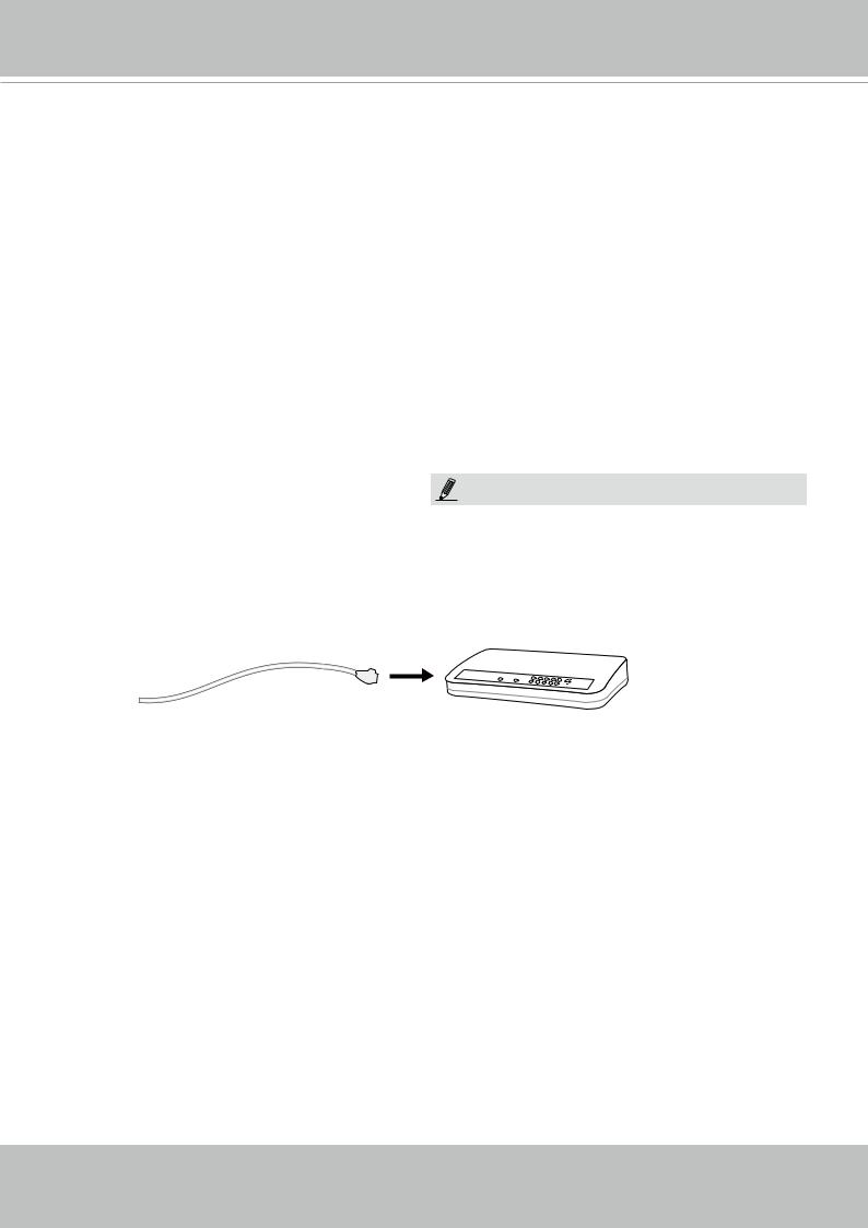
Set up the Network Camera through Power over Ethernet (PoE)
When using a PoE-enabled switch
The Network Camera is PoE-compliant, allowing transmission of power and data via a single Ethernet cable. Follow the below illustration to connect the Network Camera to a PoE-enabled
switch via an Ethernet cable.
NOTE:
1. The camera is only to be connected to PoE networks without routing to outside plants.
2. For PoE connection, use only UL listed I.T.E. with PoE output.
Power + Data Transmission |
|
PoE Switch |
|||||
|
POWER |
COLLISION |
1 |
|
|
|
LINK |
|
|
|
|
|
RECEIVE |
||
|
|
|
|
2 |
3 4 |
5 |
PARTITION |
When using a non-PoE switch
If your switch/router does not support PoE, use a PoE power injector (optional) to connect between the Network Camera and a non-PoE switch.
PoE Power Injector
(optional)
Non-PoE Switch
PARTITION
User's Manual - 13
VIVOTEK
Software Installation
Installation Wizard 2 (IW2), free-bundled software included on the product CD, helps you set up your Network Camera on the LAN.
1.Install IW2 under the Software Utility directory from the software CD.
Double click the IW2 shortcut on your desktop to launch the program.
IW2
Installation
Wizard 2
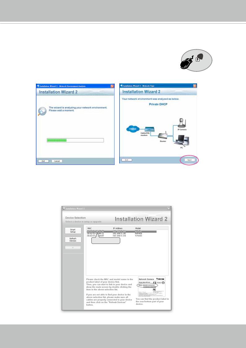
2.The program will conduct an analysis of your network environment.
After your network environment is analyzed, please click Next to continue the program.
3.The program will search for all VIVOTEK network devices on the same LAN.
4.After a brief search, the main installer window will pop up. Double-click on the MAC address that matches the one printed on the camera label or the S/N number on the package box label to open a browser management session with the Network Camera.
00-02-D1-08-32-36 |
192.168.5.109 |
CC8160 |
|
|
|
|
|
0002D1083236
14 - User's Manual
VIVOTEK
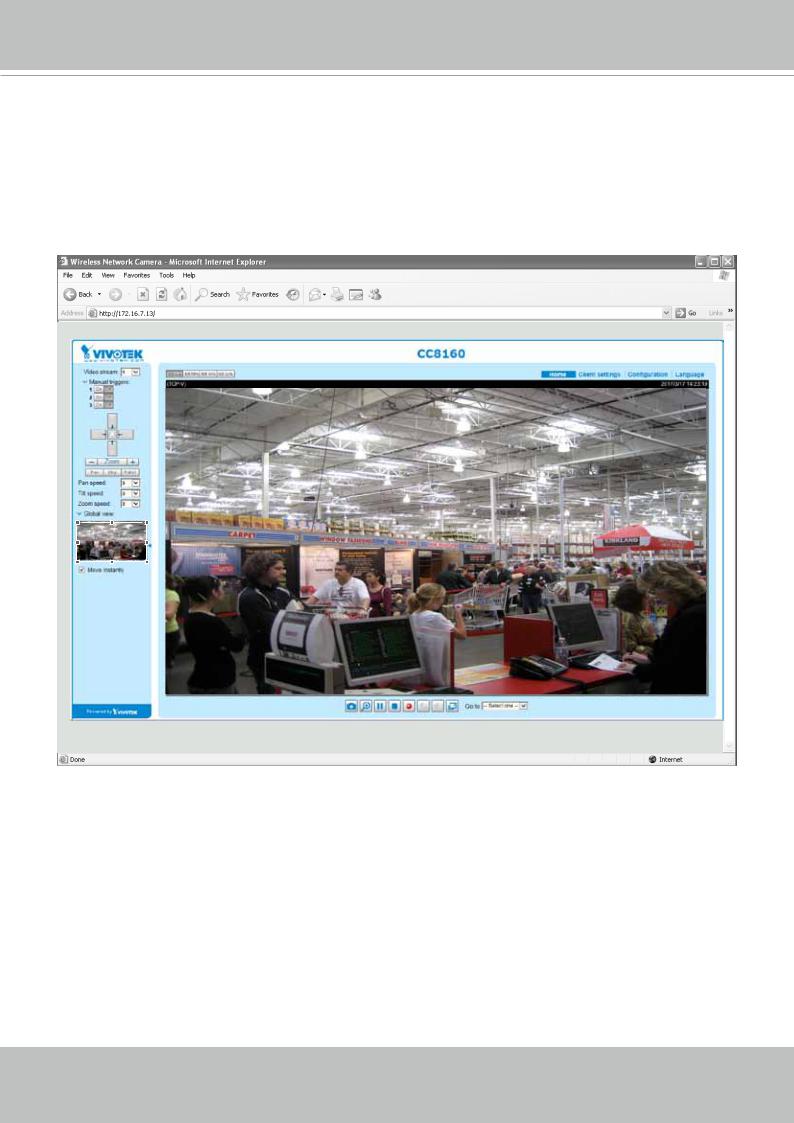
Ready to Use
1.A browser session with the Network Camera should prompt as shown below.
2.You should be able to see live video from your camera. You may also install the 32-channel recording software from the software CD in a deployment consisting of multiple cameras. For its installation details, please refer to its related documents.
User's Manual - 15
VIVOTEK
Accessing the Network Camera
This chapter explains how to access the Network Camera through web browsers, RTSP players,
3GPP-compatible mobile devices, and VIVOTEK recording software.
Using Web Browsers
 IMPORTANT:
•If you encounter this problem, try execute the Iexplore.exe program from C:\Windows\ SysWOW64. A 32-bit version of IE browser will be installed.
•On Windows 7, the 32-bit explorer browser can be accessed from here: C:\Program Files (x86)\Internet Explorer\iexplore.exe
Use Installation Wizard 2 (IW2) to access to the Network Cameras on the LAN.
If your network environment is not a LAN, follow these steps to access the Netwotk Camera:
1.Launch your web browser (e.g., Microsoft® Internet Explorer or Mozilla Firefox).
2.Enter the IP address of the Network Camera in the address field. Press Enter.
3.The live video will be displayed in your web browser.
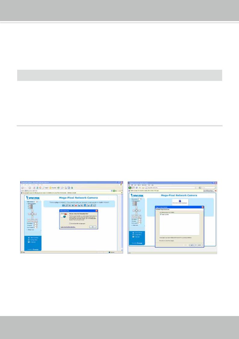
4.If it is the first time installing the VIVOTEK network camera, an information bar will prompt as shown below. Follow the instructions to install the required plug-in on your computer.
16 - User's Manual
VIVOTEK
 NOTE:
NOTE:
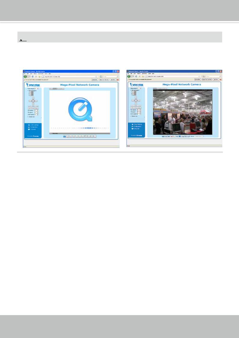
For Mozilla Firefox or Netscape users, your browser will use Quick Time to stream live video. If you do not have Quick Time on your computer, please download Quick Time from Apple Inc's website, and then launch your web browser.
User's Manual - 17
VIVOTEK
NOTE:
1.By default, your Network Camera is not password-protected. To prevent unauthorized access, it is highly recommended to configure a password for your camera later.For more information
about how to enable password protection, please refer to Security on page 77.
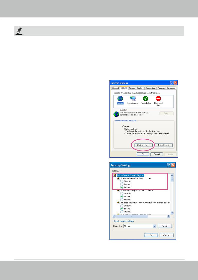
2. If you see a dialogue box indicating that your security settings prohibit running ActiveX Controls®, please enable ActiveX Controls for your browser.
To enable the ActiveX® Controls for your browser:
2-1. Choose Tools > Internet Options >
Security > Custom Level.
2-2. Look for Download signed ActiveX® controls; select Enable or Prompt. Click OK.
2-3. Refresh your web session, then install the ActiveX® control. Follow the instructions to complete installation.
18 - User's Manual
VIVOTEK
Using RTSP Players
To view the H.264 streaming media using RTSP players, you can use one of the following players that support RTSP streaming.
Quick Time Player
VLC Player
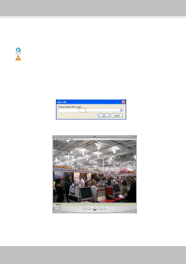
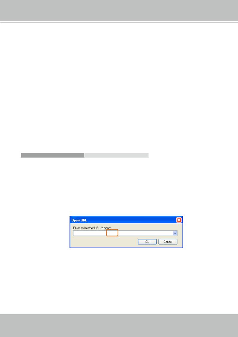
1.Launch the RTSP player.
2.Choose File > Open URL. A URL dialog box will prompt.
3.The address format is rtsp://<ip address>:<rtsp port>/<RTSP streaming access name for stream1 to stream4>
As most ISPs and players only allow RTSP streaming through port number 554, please set the
RTSP port to 554. For more information, please refer to RTSP Streaming on page 63.
For example:
rtsp://192.168.5.151:554/live.sdp
4. The live video will be displayed in your player. For more information on how to configure the
RTSP access name, please refer to RTSP Streaming on page 63 for details.
The RTSP players will show the original oval-shape image. You can access the Regional views via the ST7501 or VAST software. See page 64 for an example.
User's Manual - 19
VIVOTEK
Using 3GPP-compatible Mobile Devices
To view the streaming media through 3GPP-compatible mobile devices, make sure the Network
Camera can be accessed over the Internet. For more information on how to set up the Network
Camera over the Internet, please refer to Setup the Network Camera over the Internet on page
12.
To utilize this feature, please check the following settings on your Network Camera:
1.Because most players on 3GPP mobile phones do not support RTSP authentication, make sure the authentication mode of RTSP streaming is set to “disabled.”
For more information, please refer to RTSP Streaming on page 63.
2.As the the bandwidth on 3G networks is limited, you will not be able to use a large video size.
Please set the video and audio streaming parameters as listed below.
For more information, please refer to Stream settings on page 50.
Video Mode |
MPEG-4 |
Frame size |
176 x 144 |
Maximum frame rate |
5 fps |
Intra frame period |
1S |
Video quality (Constant bit rate) |
40kbps |
Audio type (GSM-AMR) |
12.2kbps |
3.As most ISPs and players only allow RTSP streaming through port number 554, please set the RTSP port to 554. For more information, please refer to RTSP Streaming on page 63.
4.Launch the player on the 3GPP-compatible mobile devices (e.g., VLC or Real Player).
5.Type the following URL commands in the URL field.
The address format is rtsp://<public ip address of your camera>:<rtsp port>/<RTSP streaming access name for stream 3>.
For example:
rtsp://192.168.5.151:554/live.sdp
20 - User's Manual

VIVOTEK
Using VIVOTEK Recording Software
The product software CD also contains recording software, allowing simultaneous monitoring and video recording for multiple Network Cameras. Please install the recording software; then launch the program to add the Network Camera to the Channel list. For detailed information about how to use the recording software, please refer to the user’s manual of the software or download it from http://www.vivotek.com.
User's Manual - 21

VIVOTEK
Main Page
This chapter explains the screen elements on the main page. It is composed of the following sections: VIVOTEK INC. Logo, Host Name, Camera Control Area, Configuration Area, and Live
Video Window.
VIVOTEK logo
Resize Buttons |
|
|
|
Configuration |
||
|
|
Host name |
|
|
Area |
|
|
|
|
|
|
|
|
|
|
|
||||
|
|
|
|
|
|
|
|
|
|
|
|
|
|
Camera Control
Panel
Live View window
VIVOTEK INC. Logo
Click this logo to visit the VIVOTEK website.
Host Name
The host name can be customized to fit your needs. For more information, please refer to System > General
Settings on page 33.
Tips:
The onscreen Java control can malfunction under the following situations:
A PC connects to different cameras that are using the same IP address (or the same camera running different firwmare versions).
Removing your browser cookies will solve this problem.
22 - User's Manual
VIVOTEK
Control Panel
Video Stream: This Network Cmera supports dual stream display (stream #1 and #2) simultaneously. You can select any one of them for live viewing. For more information about multiple streams, please refer to page 50 for detailed information.
Manual Trigger: Click to enable/disable an event trigger manually. Please configure an event setting before enabling this function. A total of 3 or 4 event settings can be configured. For more information about event setting, please refer to page 94. If you want to hide this item on the homepage, please go to the System > Homepage Layout > General settings > Customized button to deselect the “show manual trigger button” checkbox.
Configuration Area
Client Settings: Click this button to access the client setting page. For more information, please refer to Client Settings on page 27.
Configuration: Click this button to access more of the configuration options provided with the Network
Camera. It is suggested that a password is applied to the Network Camera so that only the administrator can configure the Network Camera. For more information, please refer to the description for the
Configuration menus on page 32.
Language: Click this button to choose a language for the user interface. Language options are available in: English, Deutsch, Español, Français, Italiano, , Português, , and . You can also change a language on the Configuration page; please refer to page 32.
Hide Button
You can click the hide button to hide the control panel or display the control panel.
|
|
|
|
|
|
|
|
|
|
|
|
|
|
|
|
|
|
|
Up |
|
||
|
|
|
|
|
|
|
|
|
|
|
|
|
|
|
|
|
|
|
||||
|
Left |
|
|
|
|
|
|
|
|
|
|
|
|
|
|
|
|
|
Return to Home Position |
|||
|
|
|
|
|
|
|
|
|
|
|
|
|
|
|
|
|
||||||
|
|
|
|
|
|
|
|
|
|
|
|
|
|
|
|
|
|
|
Right |
|
||
|
|
|
|
|
|
|
|
|
|
|
|
|
|
|
|
|
|
|
||||
|
Down |
|
|
|
|
|
|
|
|
|
|
|
|
|
|
|
|
|
|
|||
|
|
|
|
|
|
|
|
|
|
|
|
|
|
|
|
|
|
Zoom In |
|
|||
|
|
|
|
|
|
|
|
|
|
|
|
|
|
|
|
|
|
|||||
Zoom Out |
|
|
|
|
|
|
|
|
|
|
|
|
|
|
|
|
Auto Focus |
|||||
|
|
|
|
|
|
|
|
|
|
|
|
|
|
|
|
|||||||
Focus Near |
|
|
|
|
|
|
|
|
|
|
|
|
|
|
Focus Far |
|||||||
|
|
|
|
|
|
|
|
|
|
|
|
|
|
|
||||||||
Start to Auto Pan |
|
|
|
|
|
|
|
|
|
|
|
|
|
|
|
|
Auto Tracking |
|
||||
|
|
|
|
|
|
|
|
|
|
|
|
|
|
|
|
|
||||||
|
|
|
|
|
|
|
|
|
|
|
|
|
|
Start to Auto Patrol |
||||||||
|
|
|
|
|
|
|
|
|
|
|
|
|
|
|
|
|
|
|
|
|
||
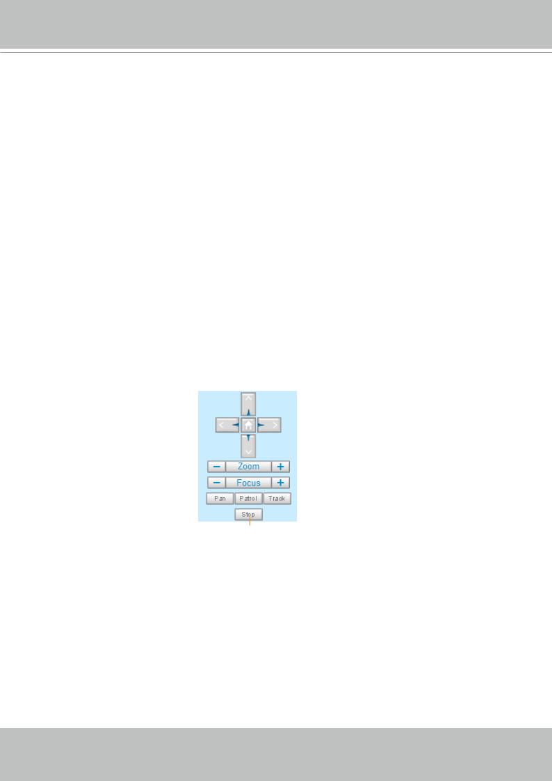
Stop Auto Panning/patrolling/tracking
Pan: Click this button to start the auto pan (360° continuous rotation).
Stop: Click this button to stop the Auto Pan, Auto Patrol, and Auto Tracking functions.
Patrol: Once the Administrator has determined the list of preset positions (including the zoom-in action on a particular position), click this button to command the camera to patrol among those positions on the Patrol List. The Network Camera will patrol continuously. For more information, please refer to PTZ control on page 93.
Track: Allows the camera to move along following the moving objects in the current field of view. If you observe an object of your interest, click this button to track the object. Note that this function does not apply in an extremely crowded area, such as a market or sidewalk full of pedestrian activities. Constant shift of tracked objects will decrease the usability of this feature.
User's Manual - 23

VIVOTEK
Once started, you can use the Stop button to stop the current action. A click on the screen can also stop the tracking action.
Another key concept is that the camera only detect movements within the current field of view.
Resize Buttons
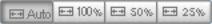 :
:
Click the Auto button, the video cell will resize automatically to fit the monitor.
Click 100% is to display the original homepage size.
Click 50% is to resize the homepage to 50% of its original size.
Click 25% is to resize the homepage to 25% of its original size.
Live Video Window
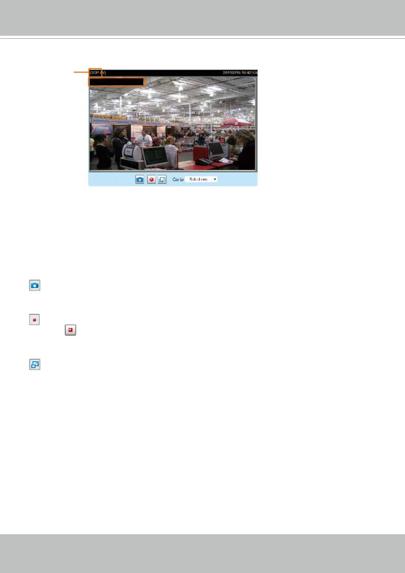
■ The following window is displayed when the video mode is set to H.264:
H.264 Protocol and Media Options |
Time |
Video Title
Title and Time 
Video (TPC-AV) |
Video 13:59:05 2017/07/04 |
|
Video 13:59:05 2017/07/04
 Video and Audio Control Buttons
24 - User's Manual
VIVOTEK
Video Title: The video title can be configured. For more information, please refer to Video settings on page 50.
H.264 Protocol and Media Options: The transmission protocol (TCP or UDP, etc.)and media options for
H.264 video streaming. For further configuration, please refer to Client Settings on page 27.
Time: Display the current time. For further configuration, please refer to Media > Image > Genral settings on page 45.
Title and Time: The video title and time can be stamped on the streaming video. For further configuration, please refer to Media > Image > Genral settings on page 45.
Video and Audio Control Buttons: Depending on the Network Camera model and Network Camera configuration, some buttons may not be available.
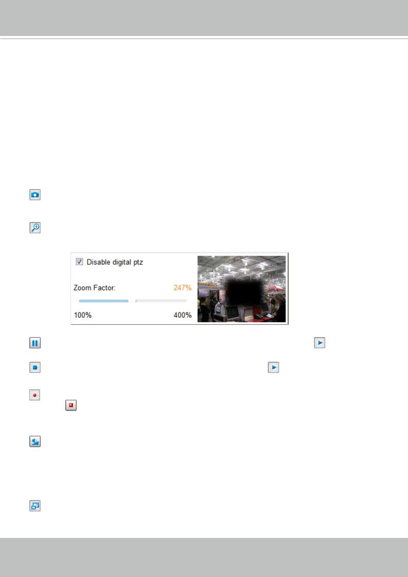
Snapshot: Click this button to capture and save still images. The captured images will be displayed in a pop-up window. Right-click the image and choose Save Picture As to save it in JPEG (*.jpg) or BMP
(*.bmp) format.
Digital Zoom: Click and uncheck “Disable digital zoom” to enable the zoom operation. The navigation screen indicates the part of the image being magnified. To control the zoom level, drag the slider bar. To
move to a different area you want to magnify, drag the navigation screen.
|
|
|
|
|
Pause: Pause the transmission of the streaming media. The button becomes the |
Resume button |
|||
after clicking the Pause button. |
|
|
||
Stop: Stop the transmission of the streaming media. Click the |
Resume button to continue |
|||
transmission. |
|
|
||
Start MP4 Recording: Click this button to record video clips in MP4 file format to your computer.
Press the |
Stop MP4 Recording button to end recording. When you exit the web browser, video |
recording stops accordingly. To specify the storage destination and file name, please refer to MP4 Saving Options on page 28 for details.
Volume: When the  Mute function is not activated, move the slider bar to adjust the volume on the local computer.
 Mute: Turn off the volume on the local computer. The button becomes the
  Audio On button after clicking the Mute button.
Full Screen: Click this button to switch to full screen mode. Press the “Esc” key to switch back to normal mode.
User's Manual - 25
VIVOTEK
■ The following window is displayed when the video mode is set to MJPEG:
Video Title
Title and Time
|
|
|
|
Time |
Video (HTTP-V) |
|
2017/03/10 17:08:56 |
||
|
|
|||
|
|
|
|
|

 Video 17:08:56 2017/03/10
 Video Control Buttons
Video Title: The video title can be configured. For more information, please refer to Media > Image on page 45.
Time: Display the current time. For more information, please refer to Media > Image on page 45.
Title and Time: Video title and time can be stamped on the streaming video. For more information, please refer to Media > Image on page 45.
Video Control Buttons: Depending on the camera model and your current configuration, some buttons may not be available.
Snapshot: Click this button to capture and save still images. The captured images will be displayed in a pop-up window. Right-click the image and choose Save Picture As to save it in JPEG (*.jpg) or BMP
(*.bmp) format.
Start MP4 Recording: Click this button to record video clips in MP4 file format to your computer.
Press the |
Stop MP4 Recording button to end recording. When you exit the web browser, video |
recording stops accordingly. To specify the storage destination and file name, please refer to MP4 Saving Options on page 28 for details.
Full Screen: Click this button to switch to full screen mode. Press the “Esc” key to switch back to normal mode.
26 - User's Manual
VIVOTEK
Client Settings
This chapter explains how to select the stream transmission mode and saving options on the local computer. When completed with the settings on this page, click Save on the page bottom to enable the settings.
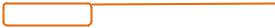
H.264 Media Options
Select to stream video or audio data or both. This is enabled only when the video mode is set to H.264.
H.264 Protocol Options
Depending on your network environment, there are four options with the transmission protocols with H.264 streaming:
UDP unicast: This protocol allows for more real-time audio and video streams. However, network packets may be lost due to network burst traffic and images may be broken. Activate UDP connection when occasions require time-sensitive responses and the video quality is less important. Note that each unicast client connecting to the server takes up additional bandwidth and the Network Camera allows up to ten simultaneous accesses.
UDP multicast: This protocol allows multicast-enabled routers to forward network packets to all clients requesting streaming media. This helps to reduce the network transmission load of the Network Camera while serving multiple clients at the same time. Note that to utilize this feature, the Network Camera must be configured to enable multicast streaming at the same time. For more information, please refer to RTSP Streaming on page 63.
TCP: This protocol guarantees the complete delivery of streaming data and thus provides better video quality. The downside of this protocol is that its real-time effect is not as good as that of using the UDP protocol.
HTTP: This protocol allows the same quality as TCP protocol without needing to open specific ports for streaming under some network environments. Users behind a firewall can utilize this protocol to allow camera’s streaming data to pass through.
User's Manual - 27
VIVOTEK
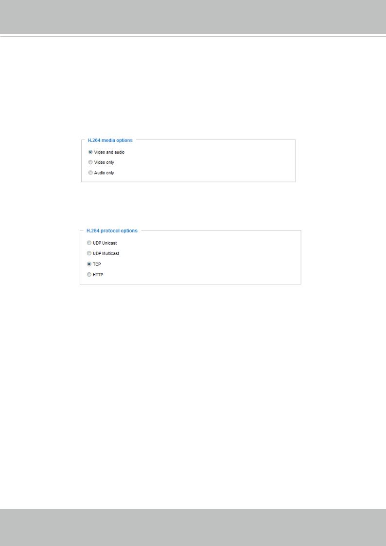
MP4 Saving Options
Users can record live video as they are watching it by clicking the “Start MP4 Recording” button on the main page. Here, you can specify the storage destination and file name.
Folder: Specify a storage destination for the recorded video files.
File name prefix: Enter the text that will be appended to the front of the video file name.
Add date and time suffix to the file name: Select this option to append the date and time to the end of the file name.
CLIP_20110328-180853
File name prefix Date and time suffix
The format is: YYYYMMDD_HHMMSS
Local Streaming Buffer Time
Due to possible occurrences of unsteady network transmission, live streaming may lag and not be very smoothly. If you enable this option, the live streaming will be stored on the camera’s buffer for a few seconds before being played on the client computer’s live view window. This helps produce a smoothlier live streaming. If you enter a vlue of 3,000 milliseconds, the streaming will delay for 3 seconds.
28 - User's Manual
VIVOTEK
Joystick Settings
Enable Joystick
Connect to the USB plug of the joystick to a USB port on your management computer. Once a USB joystick is connected, the related joystick configuration will be available on the Client settings window.
The joystick should work properly without installing any other driver or software.
Then you can begin to configure the joystick settings of connected devices. Please follow the instructions below to enable joystick settings.
1. Click on the Configure buttons button. If your joystick is working properly, it will be displayed on the drop-down list.
User's Manual - 29

VIVOTEK
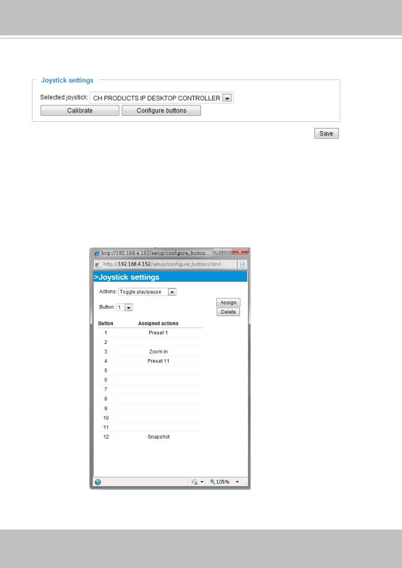
Buttons Configuration
In the Joystick Settings window, you can use the combinations of pull-down menus, Actions and Button number, to assign joystick buttons with different functions. The number of buttons may differ from the joystick you attached.
Please follow the steps below to configure your joystick buttons:
1.Select the number of the button you want to configure from its pull-down list.
For example: Assign Preset 1 (move to preset 1 position) to Button 1.
2.Select an action from the Actions menu. Click Assign to associate the button with an action.
3.Your configuration will be automatically saved.
4.To disable an assignment, select the number of a button, and then click the Delete button. The associated action will then be cleared.
5.Repeat the above process to assign actions to other buttons. When done, simply close the configuration window.
30 - User's Manual
Loading...