


 Loading...
IB9387-H, IB9387-EH, IB9387-HT, IB9387-EHT
IB9387-LPR
Bullet Network Camera
User’s Manual
5MP • Outdoor • IP66/IP67 • IK10 • Day & Night • Remote Focus (T)
WDR Pro II • Smart Stream III • SNV II • 30M Smart IR
 Rev. 1.1

VIVOTEK
Table of Contents |
|
Overview .................................................................................................................................................................... |
3 |
Revision History |
4 |
Read Before Use |
4 |
Package Contents |
5 |
Symbols and Statements in this Document |
5 |
Physical Description |
6 |
Hardware Installation |
8 |
Software Installation |
15 |
Installation of Optional Accessories |
23 |
Network Deployment |
26 |
Ready to Use |
27 |
Accessing the Network Camera |
30 |
Using Web Browsers |
30 |
Using RTSP Players |
33 |
Using 3GPP-compatible Mobile Devices |
34 |
Using VIVOTEK Recording Software |
35 |
Main Page................................................................................................................................................................ |
36 |
Client Settings ......................................................................................................................................................... |
41 |
Configuration........................................................................................................................................................... |
46 |
System > General settings |
47 |
System > Homepage layout |
49 |
System > Logs |
52 |
System > Parameters |
54 |
System > Maintenance |
55 |
Media > Image |
59 |
Media > Video |
72 |
Media > Video |
73 |
Media > Video |
74 |
Media > Audio |
83 |
Network > General settings |
85 |
Network > Streaming protocols |
92 |
Network > SNMP (Simple Network Management Protocol) |
102 |
Network > FTP |
103 |
Security > User accounts |
104 |
Security > HTTPS (Hypertext Transfer Protocol over SSL) |
106 |
Security > Access List |
113 |
PTZ > PTZ settings |
119 |
Event > Event settings |
123 |
Applications > Motion detection |
137 |
Applications > DI and DO |
138 |
Applications > Tampering detection |
139 |
Applications > Audio detection |
140 |
Applications > Shock detection |
142 |
Applications > Package management - a.k.a., VADP (VIVOTEK Application Development Platform) |
143 |
2 - User's Manual

VIVOTEK
Recording > Recording settings 146 Local storage > SD card management 151 Local storage > Content management 152 Appendix 155 URL Commands for the Network Camera 155 Technical Specifications 371 Technology License Notice 373 Electromagnetic Compatibility (EMC) 374
Overview
The IB9387 series is a camera line to comes embedded with the Smart Motion Detection feature. The Smart Motion detection, with Human detection and tunable time filter, can eliminate the defects of traditional motion detection and facilitate the configuration at a surveillance site.
To learn more about this feature, download its User Guide in: http://download.vivotek.com/downloadfile/solutions/vadp/smart-motion-detection-manual_ en.pdf
A key feature in the Smart Motion detection is the Human detection. Based on a human silhouette database and the rapid responses via an artificial neural network technology, the Smart engine instantly recognizes human appearances in a video surveillance area. Since humans are the objects of interest in the majority of video surceillance, the Human detection feature enables users to quickly configure his installation.
With Human detection, light changes or swaying vegetation, vehicles passing by, or animal activities in the scene are not taken as event triggers. Only human activities will trigger an event. This helps reduce false alarms and the time and efforts for a camera configuration.
The IB9387 series is an outdoor bullet network camera capable of 2560 x 1944 resolution at 30 fps. With the most updated VIVOTEK SNV and WDR Pro technology, the IB9387 series is capable of capturing the highest quality images in both low light and high contrast environments.
The IB9387 series also offers the best in night time surveillance technology. By adopting Smart IR II technology from VIVOTEK speed domes, the IB9387 IR illuminators now align with the remote focus lens’ focus angle to provide the best IR image quality at any lens setting. This feature optimizes IR intensity, reduces IR hotspots, and increases the IR effective range up to 30 meters.
User's Manual - 3

VIVOTEK
Revision History
■Rev. 1.0: Initial release.
■Rev. 1.1: Added information for IB9387-LPR.
Read Before Use
The use of surveillance devices may be prohibited by law in your country. The Network Camera is not only a high-performance web-ready camera but can also be part of a flexible surveillance system. It is the user’s responsibility to ensure that the operation of such devices is legal before installing this unit for its intended use.
It is important to first verify that all contents received are complete according to the Package Contents listed below. Take note of the warnings in the Quick Installation Guide before the Network Camera is installed; then carefully read and follow the instructions in the Installation chapter to avoid damage due to faulty assembly and installation. This also ensures the product is used properly as intended.
The Network Camera is a network device and its use should be straightforward for those who have basic networking knowledge. It is designed for various applications including video sharing, general security/surveillance, etc. The Configuration chapter suggests ways to best utilize the Network Camera and ensure proper operations. For creative and professional developers, the URL Commands of the Network Camera section serves as a helpful reference to customizing existing
homepages or integrating with the current web server.
4 - User's Manual
VIVOTEK
Package Contents
■IB9387 (w/o junction box)
■L-wrench, desiccant bag, screws.
■Sunshield and screws.
■Quick Installation Guide & alignment sticker.
■AM-719 Junction box (separately purchased).
 WARNING:
1.IR lights emit from ths product.
2.Use appropriate shielding or eye protection.
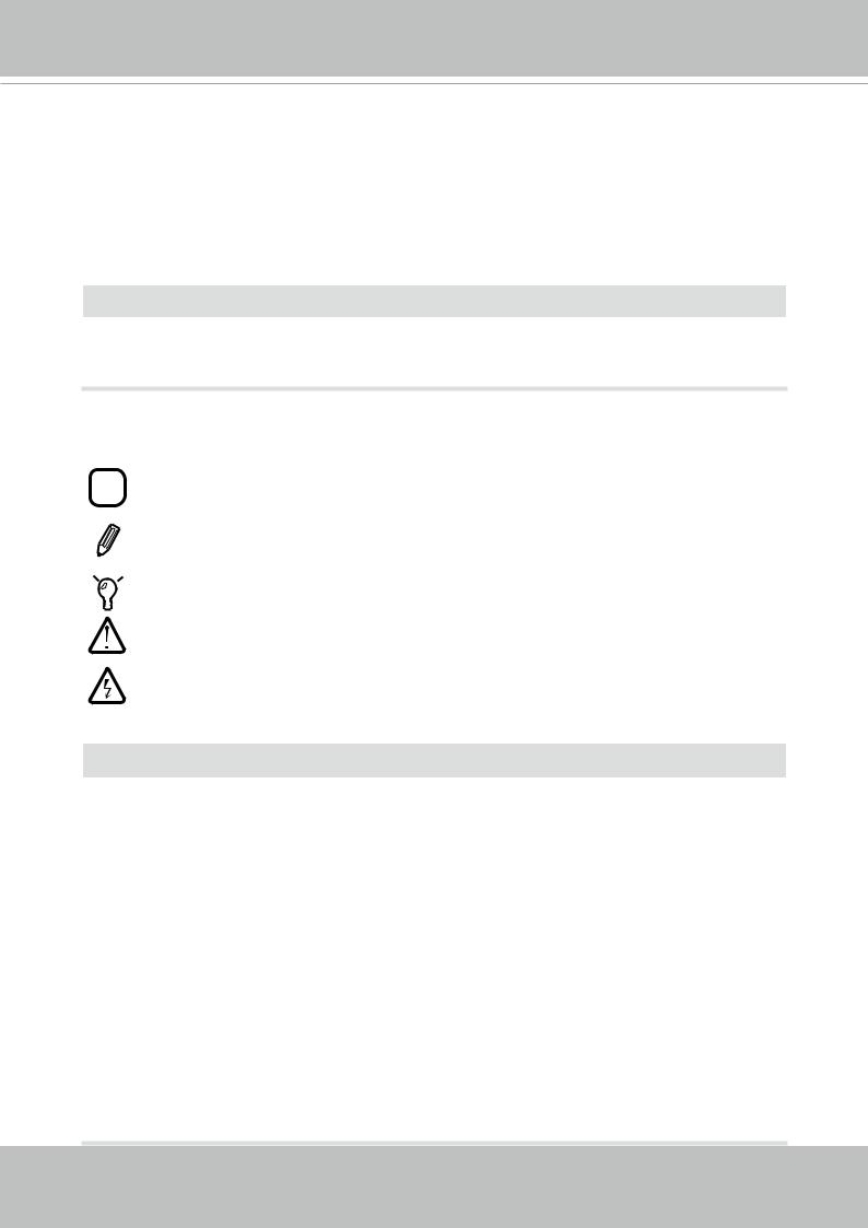
Symbols and Statements in this Document
|
i |
|
INFORMATION: provides important messages or advices that might help prevent |
||||
|
|
inconvenient or problem situations. |
|||||
|
|
|
|
|
|
|
NOTE: Notices provide guidance or advices that are related to the functional integrity of |
|
|
|
|
|
|
|
the machine. |
|
|
|
|
|
|
|
Tips: Tips are useful information that helps enhance or facilitae an installation, function, |
|
|
|
|
|
|
|
|
|
|
|
|
|
|
|
|
|
|
|
|
|
|
|
or process. |
|
|
|
|
|
|
|
WARNING: or IMPORTANT:: These statements indicate situations that can be |
|
|
|
|
|
|
|
dangerous or hazardous to the machine or you. |
|
|
|
|
|
|
|
Electrical Hazard: This statement appears when high voltage electrical hazards might |
|
|
|
|
|
|
|
occur to an operator. |
 IMPORTANT:
1.The camera is only to be connected to PoE networks without routing to outside plants.
2.For PoE connection, use only UL listed I.T.E. with PoE output.
1.La caméra ne doit être raccordée qu’à des réseaux PoE, sans routage vers des installations extérieures.
2.Pour les raccordements PoE, utilisez uniquement un équipement de TI homologué UL, avec une sortie PoE.
Use the camera only with a DC power supply that is UL listed, and limited power source
(LPS) certified. The power supply should bear the UL listed and LPS marks. The power supply should also meet any safety and compliance requirements for the country of use.
n’utilisez la caméra qu’avec un bloc d’alimentation CC homologué UL, ainsi qu’avec une alimentation limitée (LPS) certifiée. Le bloc d’alimentation doit porter les indications d'homologation UL et LPS. Il doit également répondre aux exigences en matière de sécurité et de conformité relatives au pays d’utilisation.
User's Manual - 5
VIVOTEK
Physical Description
Outer View
Sunshield
IR LEDs
Lens
Inner View
IB9387-HT, IB9387-EHT
64GB 10

 1
1
 I
I
IB9387-H, IB9387-EH
64GB 10

 1
1
 I
I
6 - User's Manual
VIVOTEK
 NOTE:
NOTE:
Some of the suffix syntax used in model naming are listed below:
E w/ heater for extreme weather
Fx Focal length w/ number
T w/ Remote focus lens
R w/ PoE repeater
H w/ High Dynamic Range functionality
 IMPORTANT:
802.3at
ON |
|
7 |
5 |
3 |
1 |
|
|
|
|
|
|
|
|
|
|
|
100~240V |
LAN/PoE |
|
|
|
9 |
10 |
|
AC |
|
|
|
|
|
|
OFF |
|
8 |
6 |
4 |
2 |
GE LAN |
GE LAN |
|
|
12/24V 1A or 2A 
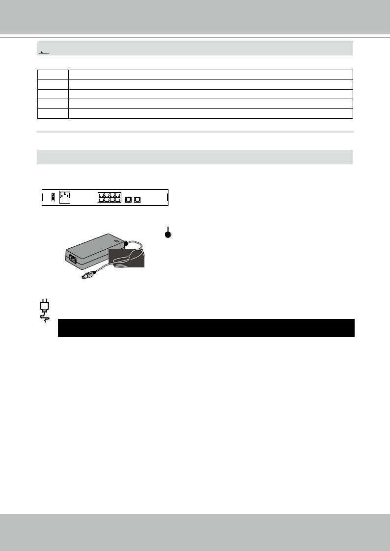
The E model camera comes with an embedded heater and requires an 802.3at PoE switch or 12V/24V 2A power.
|
Operating |
Consumption & Power Input |
|
|
Temperature |
|
|
|
-40ºC ~ 0ºC, heater |
PoE 802.3at - max. 24W (PoE Plus mid-span or switch) |
|
|
on |
|
|
|
-40ºC ~ 0ºC, heater |
DC 12V input - 2.5A |
|
|
on |
|
|
|
≥0ºC, heater off |
DC 12V input - 1A |
|
|
|
|
|
User's Manual - 7
VIVOTEK
Hardware Installation
 IMPORTANT:
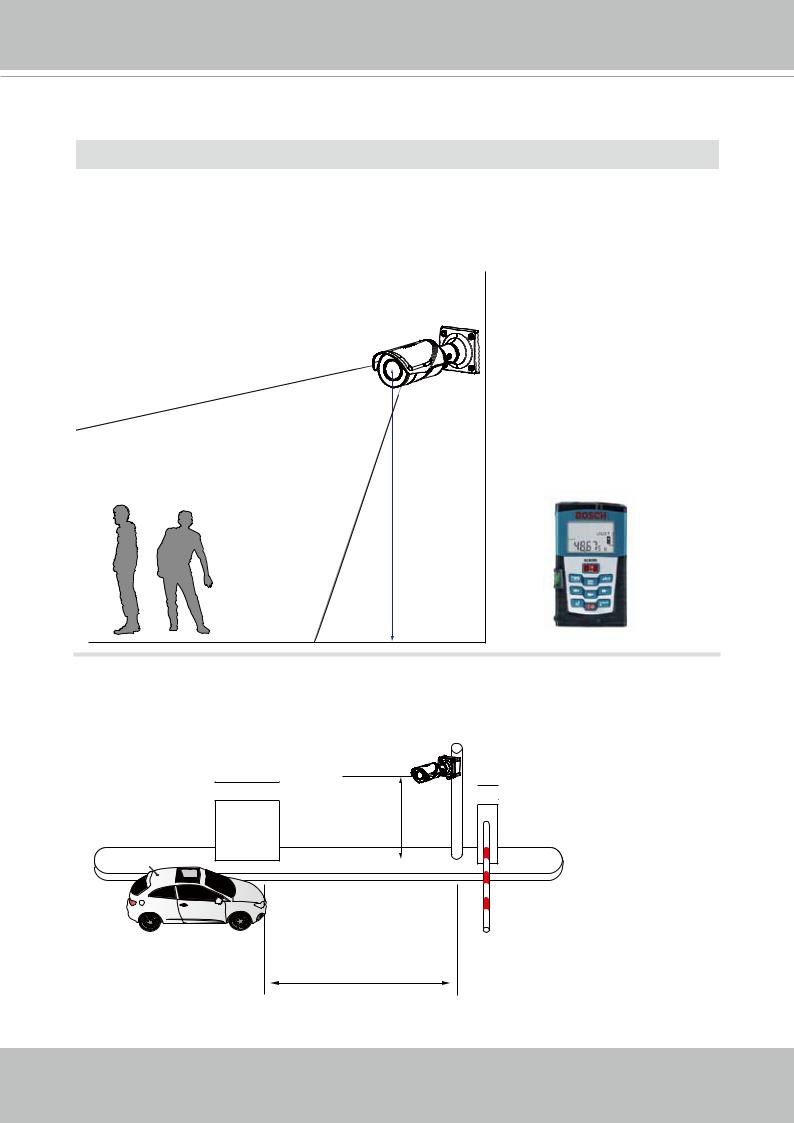
If you plan to use the Human Detection feature, make sure you measure the height of your camera. The height information is important for the accuracy of the video analytics results.
Some of the other perspective information are automatically collected by the onboard
S-sensor. The height information enables the horizontal and vertical keystone corrections of the field of view.
Installation height
If you are installing the IB9387-LPR for vehicle access control, note below for the appropriate installation position.
0.5 ~ 1.5m
2 ~ 6m
8 - User's Manual

VIVOTEK
1.Jot down the camera's MAC address for later reference.


 XXXXXX


 0002D10766AD
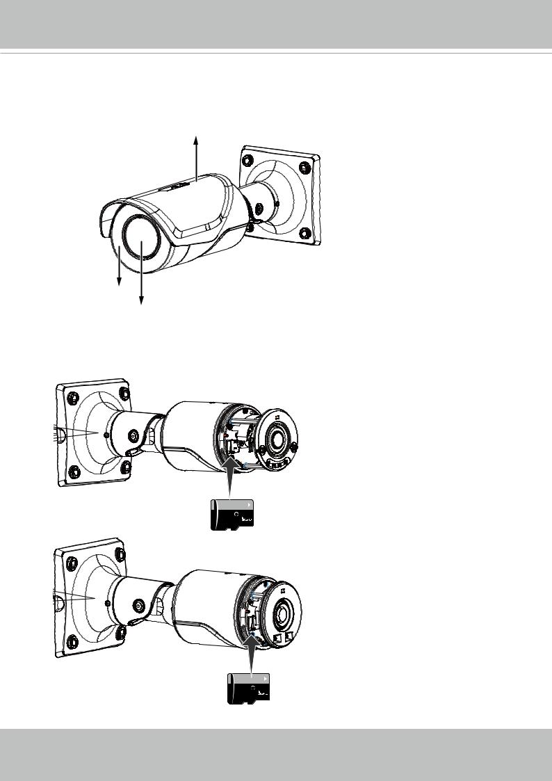
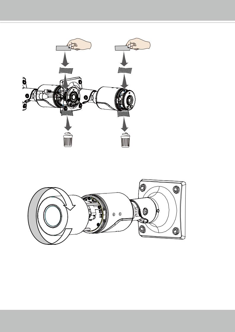
2.Turn the front section of the camera counter-clockwise to remove the front section.
3.Install a MicroSD card.
IB9387-HT, IB9387-EHT
IB9387-H, IB9387-EH
User's Manual - 9
VIVOTEK
4.Replace the desiccant bag on the side of the camera infrastructure.
|
|
|
|
|
|
|
|
|
|
IB9387-HT, |
IB9387-H, |
|
|
||||||
IB9387-EHT |
IB9387-EH |
|
|
||||||
|
|
|
|
|
|
|
|
|
|
|
|
|
|
|
|
|
|
|
|
|
|
|
|
|
|
|
|
|
|
|
|
|
|
|
|
|
|
|
|
|
|
|
|
|
|
|
|
|
|
5. Install the front section by turning it clock-wise until it is tightly fastened.
10 - User's Manual
VIVOTEK
6. Install the sunshield.
7.If used, connect the DI/DO, or audio wires to the terminal connectors.
AU+
AU-
MIC P
MIC N
DO+ (5V)
DO-
DI+
DI-
User's Manual - 11

VIVOTEK
8.Pass an Ethernet cable through the waterproof cable gland components, and through the rubber seal as shown below. Connect the Ethernet cable to the camera's RJ45 onnector.
5. |
|
|
5 ~ 6. |
||
|
|
5mm |
|
||
|
|
|
|
|
|
9. Use the alignment sticker to drill mounting holes on the wall. If preferred, drill a routing hole. Install the camera by hammer in the wall anchors and drive screws.
12 - User's Manual
VIVOTEK
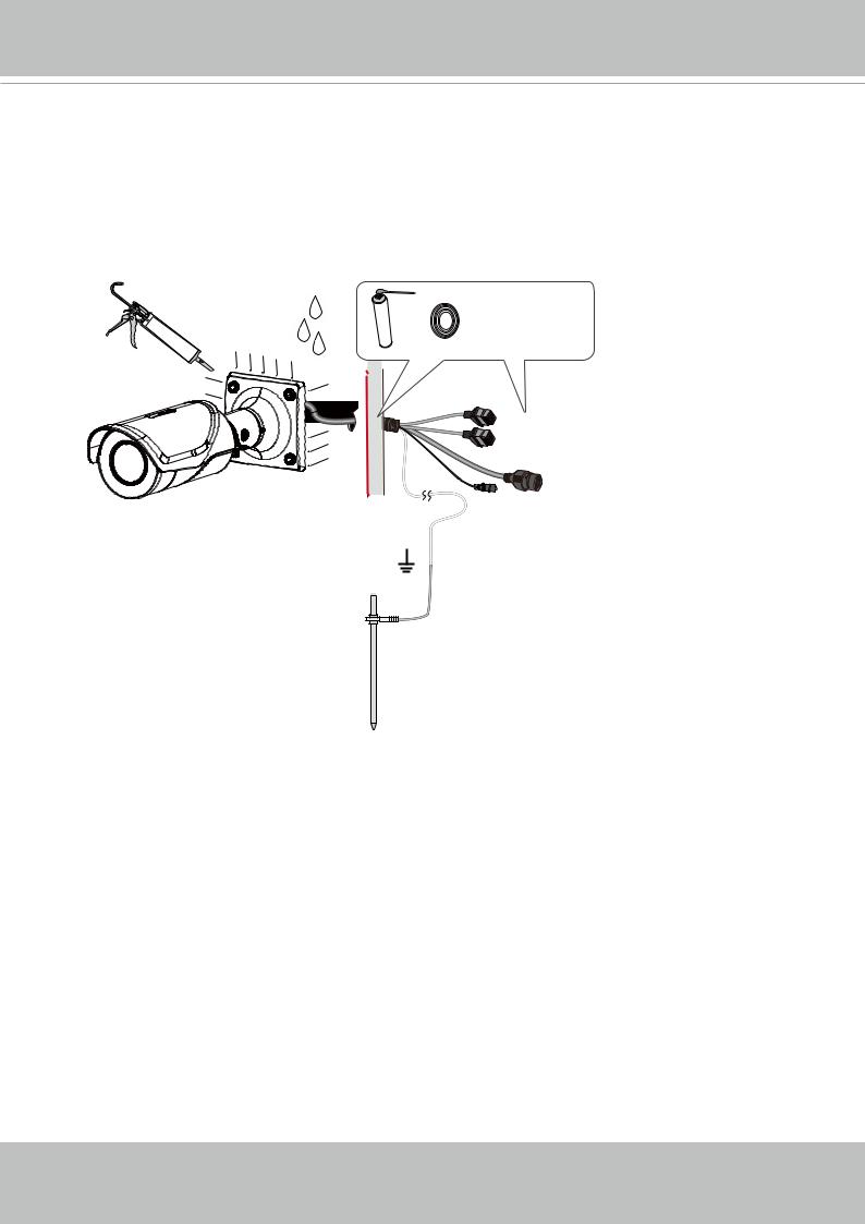
10.Use putties to seal the cable joints for water-proofing. Connect the ground wire to a grounded earth rod with a resistance smaller than 4Ω, with a section area larger than
25mm2, to a ground rod 1.5 meters into the ground.
You can also caulk the peripherals of the camera bracket if the junction box is not in use.
The ground wire is user-supplied.
1.5m
3M 2151 series
User's Manual - 13
VIVOTEK
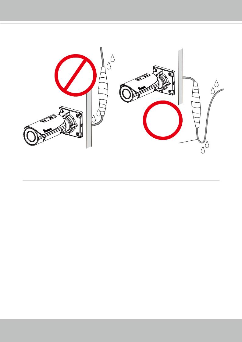
It is also very important to route cables to form a drip loop. Leakage or moisture can gather in condensation into water drops and run along the cable. A drip loop ensures no water gets to the camera.
Drip loop
14 - User's Manual
VIVOTEK
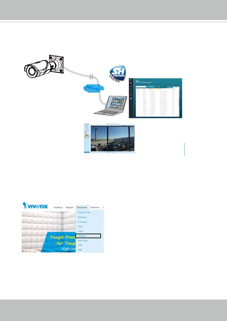
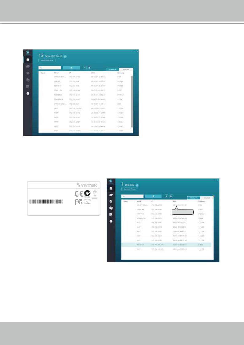
11.Please visit VIVOTEK’s website to Install the "Shepherd” software utility. The program will search for VIVOTEK Video Receivers, Video Servers or Network Cameras on the same LAN.
Double-click on the camera’s MAC address to open a web console with the camera.
Shepherd
LAN
Browser
Software Installation
12. Install the Shepherd utility, which helps you locate and configure your Network Camera in the local network. If your camera comes without the CD, go to VIVOTEK’s website, and locate the utility in the Downloads > Software page.
User's Manual - 15
VIVOTEK
12-1. Run the Shepherd utility.
12-2. The program will conduct an analysis of your network environment.
12-3. The program will search for all VIVOTEK network devices on the same LAN.
12-4. After a brief search, the installer window will prompt. Click on the MAC and model name that matches the one printed on the product label. You can then double-click on the address to open a management session with the Network Camera.
Network Camera
Model No: IB9387-HT
MAC:0002D1730202 RoHS
This device complies with part 15 of the FCC rules. Operation is subject to the following two conditions: |
IB8360IB9387-WHT |
192.168.4.151 |
00-02-D1-73-02-02 |
|
|
|
|
||
(1)This device may not cause harmful interference, and |
|
|
|
|
(2) this device must accept any interference received, including interference that may cause undesired operation. |
|
|
0002D1730202 |
|
Pat. 6,930,709 |
Made in Taiwan |
|
|
|
|
|
|
||
16 - User's Manual
VIVOTEK
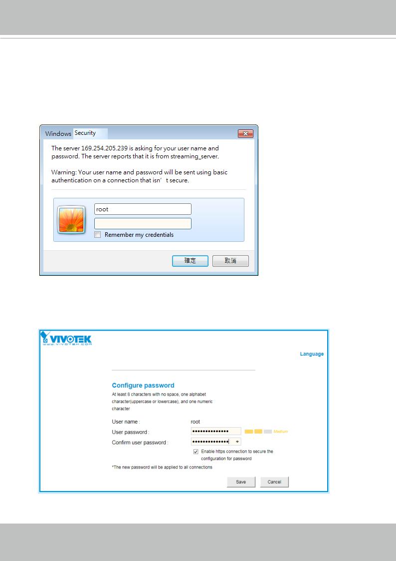
Forceful Password Configuration
13. The first time you log in to the camera, the firmware will prompt for a password configuration for security concerns.
13-1. Since your camera is used for the first time, there is no password. Enter “root” as the user name, and nothting for the password.
13-2. Enter the combination of alphabetic and numeric characters to fulfill the password strength. requirement. The default name for the camera administrator is “root”, and can not be changed.
User's Manual - 17
VIVOTEK
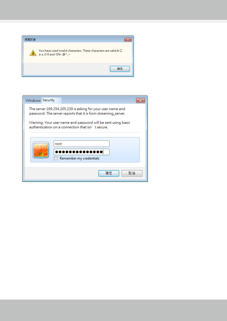
Some, but not all special ASCII characters are supported: !, $, %, -, ., @, ^, _, and ~.
You can use them in the password combination.
13-3. Another prompt will request for the password you just configured. Enter the password and then you can start configure your camera and see the live view.
18 - User's Manual
VIVOTEK
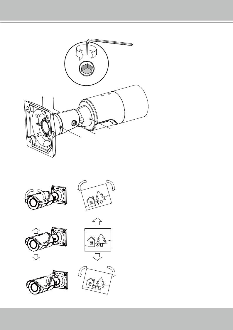
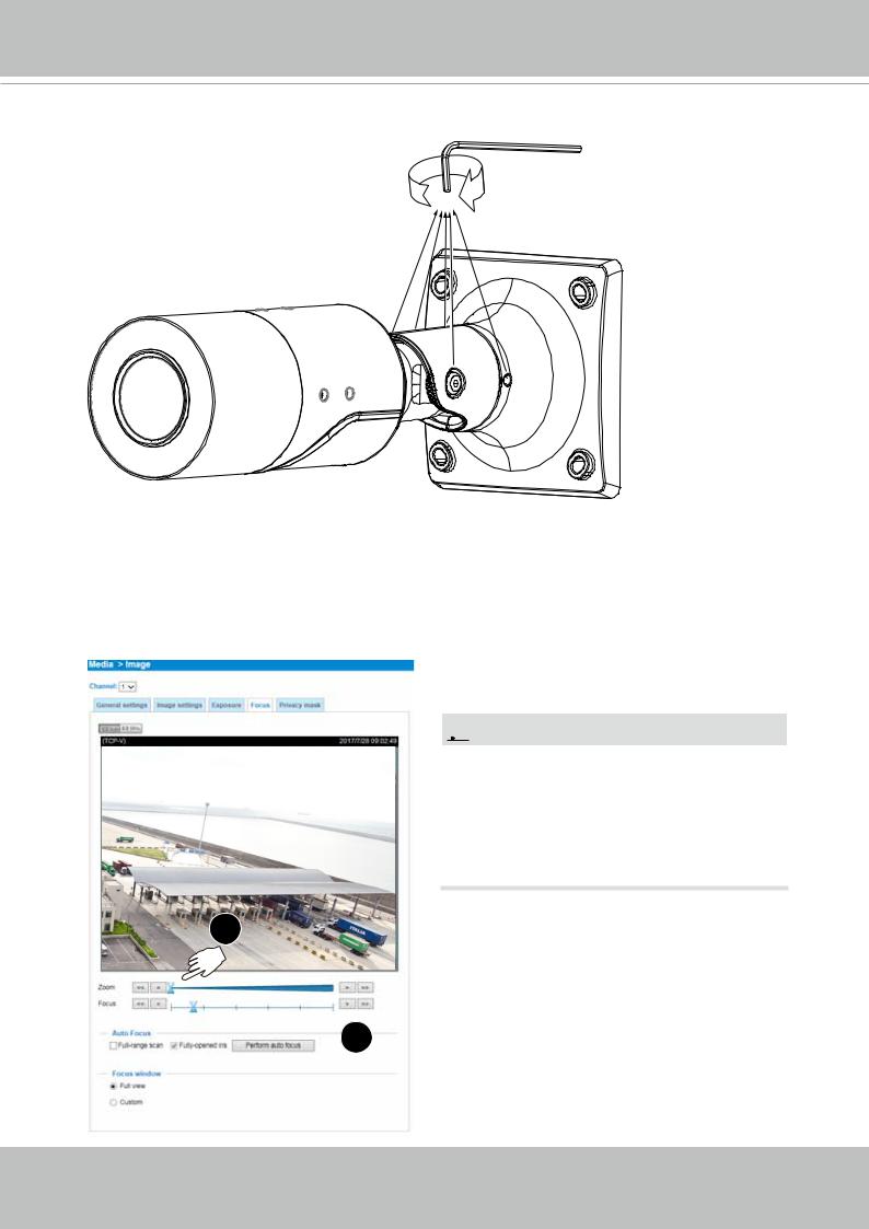
14.Loosen, but not completely remove, the retention screws on the wall-mount bracket to adjust the camera’s shooting direction. You can pan, tilt, or rotate the camera.
3 2
 1
1
 3 2
3 2
15. According to the live view, adjust the shooting direction.
1
2
3
User's Manual - 19
VIVOTEK
16. Tighten the retention screws when you are statisfied with the field of view.
17.From a web console, open the firmware configuration page. Enter the Configuration > Media > Image > Focus page. You will see a live stream on screen. If preferred, you can zoom in on the scene. Use the “Perform Auto Focus” function to automatically tune to a best image focus. Check the live view to ensure the image is in focus.
Configuration > Media > Image > Focus
 NOTE:
NOTE:
The IB9387-H is a fixed-lens model, and does not support the Zoom and Auto Focus function.
The "T" models comes with a motorized focus lens.
1
 2
2
20 - User's Manual
VIVOTEK
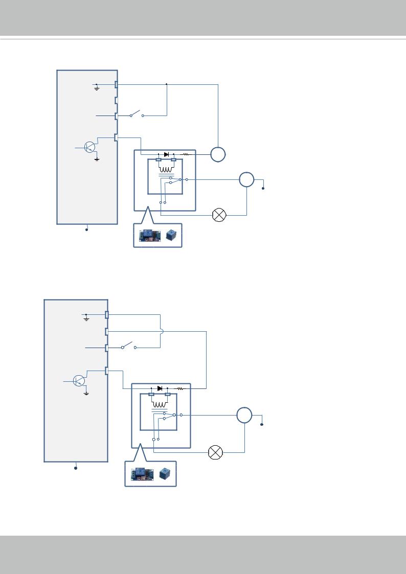
DI/DO Diagram
1.The DO+ pin provides a 5V output, and the max. load is 50mA.
2.The max. voltage for DOpins is 30VDC (External power).
In order to control AC devices, the following diagram can be taken into consideration. This diagram uses a relay to control the ON/OFF condition of the AC device.
3.An external relay can be triggered by using the DO+ or by an external power source, depending on the type of relay you use.
4.In case of using an individual relay (instead of using a relay module), for protection against voltage or current spikes, a transient voltage suppression diode must be connected in parallel with the inductive load.
Dry contact with external DC power source to supply a relay. Dry contact is the safest connection to protect devices.
DI-
DO+
DI+
DO-
DC 0V
Switch
Photo
Coupler
DC External DC power
|
DC 0V |
External AC power |
|
with Protected Earth |
|
|
AC |
|
NO |
NC |
PE |
|
Relay |
|
|
|
|
|
External Device |
|
PE
User's Manual - 21
VIVOTEK
Wet contact with external DC power source to supply a relay.
DI-
DO+ |
DI+ |
DO- |
PE
Switch
DC 0V
DC External DC power
|
|
External AC power |
|
AC |
with Protected Earth |
NO |
NC |
PE |
|
Relay |
|
|
|
|
|
External Device |
|
Dry contact and using camera’s DO+ to supply a relay.
DI-
DO+ |
|
|
DI+ |
Switch |
|
DO- |
|
|
|
|
AC |
|
NO |
NC |
|
|
Relay |
|
|
External Device |
PE
External AC power with Protected Earth
PE
22 - User's Manual
VIVOTEK
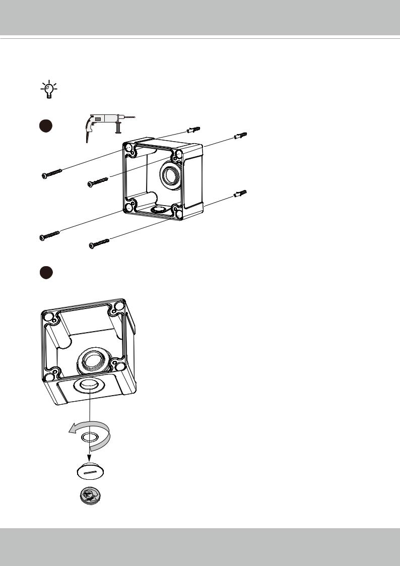
Installation of Optional Accessories
Use the included drill-hole template to drill mounting holes on a wall. Secure the conduit box to wall using the included screws.
AM-719
1
2 Loosen and remove the plastic cap under the conduit box.
User's Manual - 23
VIVOTEK
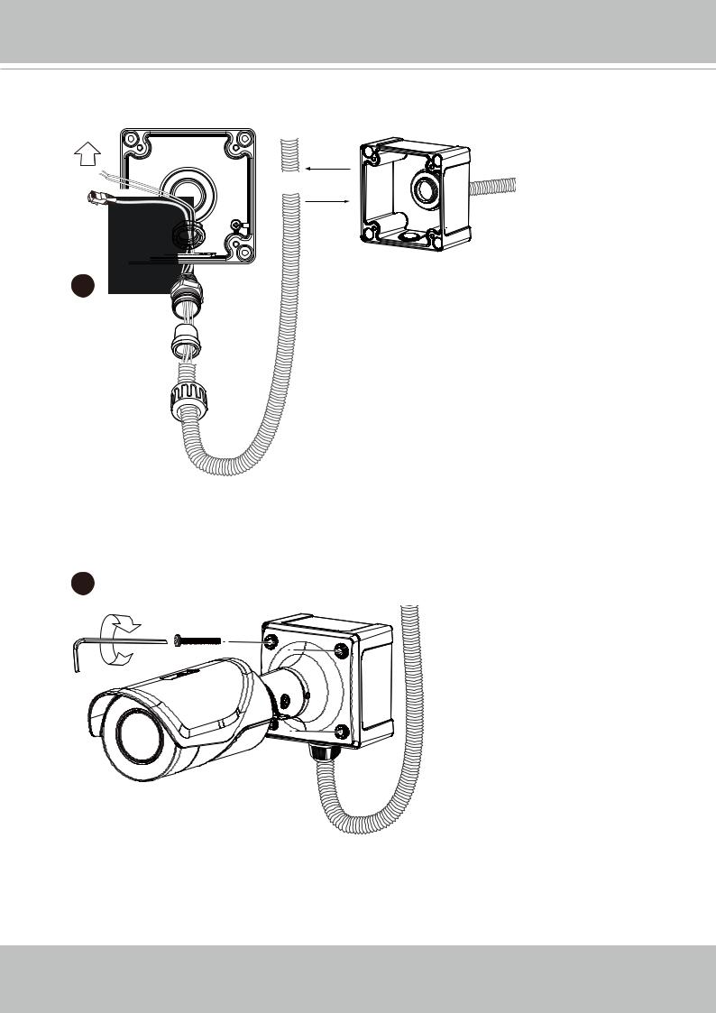
Install a 3/4" conduit along with its connector to the conduit hole either at the center of at the bottom. Route cables through the conduit.

 OR
OR
3
3/4”
Secure the camera to the conduit box using the included pan head screws. Carefully arrange the cabling connections inside the conduit box.
4
x4
24 - User's Manual
VIVOTEK
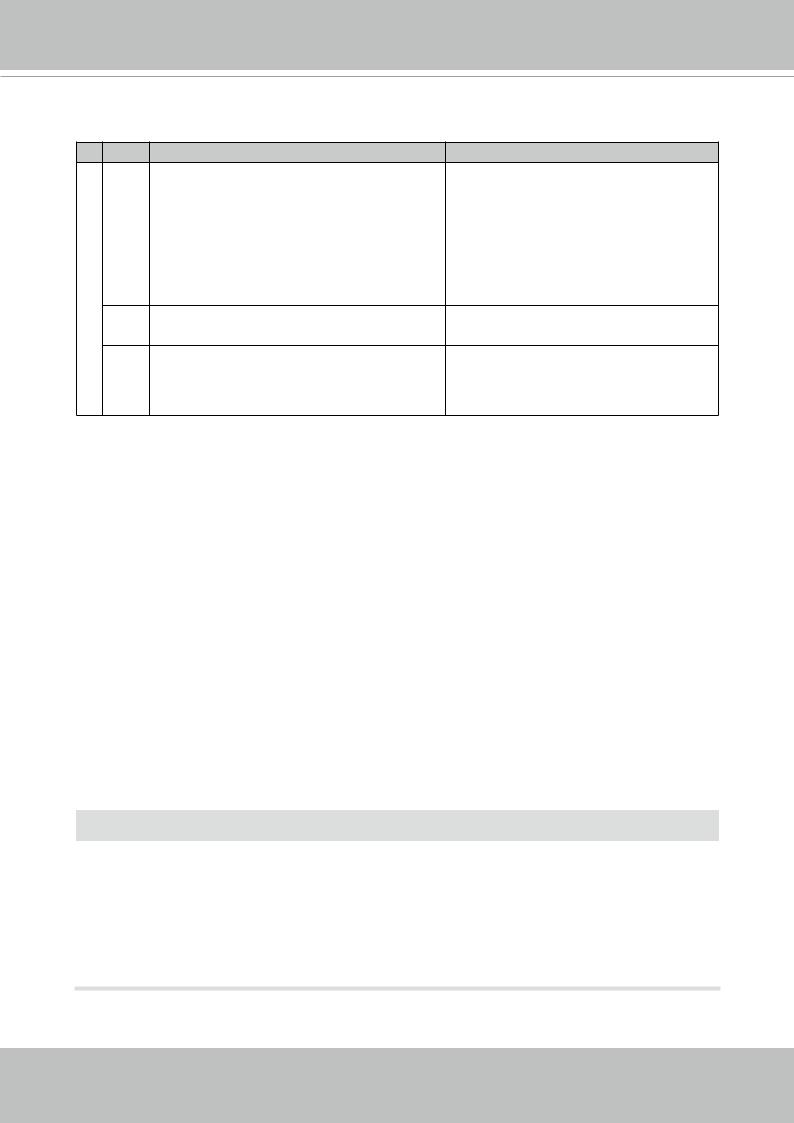
LED Definitions
Definition LED
Item |
LED status |
Description |
1 |
Steady Red |
Powered and system booting, or network |
|
|
failed |
|
Red LED off |
Power off |
|
Green LED off |
Network is disconnected |
2 |
Steady Red and Green LED blinks every 1 |
Connected to network |
|
sec. |
|
3 |
Green LED blinks every 1 sec. and RED |
Upgrading firmware |
|
LED blinks consecutively every 0.15 sec. |
|
4Green and RED blink every 0.15 sec, Green Restoring defaults and RED light on, then blink again.
5RED LED is on, Green LED blinks and RED Status after a reset (network connected) LED is constantly on.
Green and RED LEDs are constantly on. |
Status after a reset (network |
|
disconnected) |
Hardware Reset
The reset button is used to reset the system or restore the factory default settings. Sometimes resetting the system can return the camera to normal operation. If the system problems remain after reset, restore the factory settings and install again.
Reset: Press the recessed reset button. Wait for the Network Camera to reboot.
Restore: Press and hold the reset button until the status LED rapidly blinks. Note that all settings will be restored to factory default. Upon successful restore, the status LED will blink green and red during normal operation.
SD/SDHC/SDXC Card Capacity
This network camera is compliant with SD/SDHC/SDXC 16GB / 8GB / 32GB / 64GB and other preceding standard SD cards.
 IMPORTANT:
If DC power is preferred, it should comply with: O/P: 12VDC, 2A min., L.P.S. per IEC 60950-1.
Si l'alimentation CC est préférable, elle devrait être conforme avec ce qui suit : Sortie : 12
VCC, 2 A min., alimentation limitée à conformité CEI 60950-1.
User's Manual - 25

VIVOTEK
Network Deployment
General Connection (PoE)
When using a PoE-enabled switch
The Network Camera is PoE-compliant, allowing transmission of power and data via a single Ethernet cable. Follow the below illustration to connect the Network Camera to a PoEenabled switch via Ethernet cable.
|
|
|
802.3af |
|
|
PoE Switch |
||
|
|
|
802.3at for IB9387-EH and -EHT
 When using a non-PoE switch
Use a PoE power injector (optional) to connect between the Network Camera and a nonPoE switch.
PoE Power Injector (optional)
802.3at for IB9387-EH and -EHT
Non-PoE Switch
NOTE:
1.The camera is only to be connected to PoE networks without routing to outside plants.
2.For PoE connection, use only UL listed I.T.E. with PoE output.
26 - User's Manual

VIVOTEK
Ready to Use
1.A browser session with the Network Camera should prompt as shown below.
2.You should be able to see live video from your camera. You may also install the
32-channel recording software from the software CD in a deployment consisting of multiple cameras. For its installation details, please refer to its related documents.
 IMPORTANT:
•The "E" models, e.g., IB9387-EH and -EHT, are able to operate in low temperature environments. However, when starting these cameras in a very low termperature condition, e.g., -40ºC, the embedded heater may take half an hour to warm up the camera. When the temperature within the canister reaches -10ºC, the camera automatically starts.
User's Manual - 27
VIVOTEK
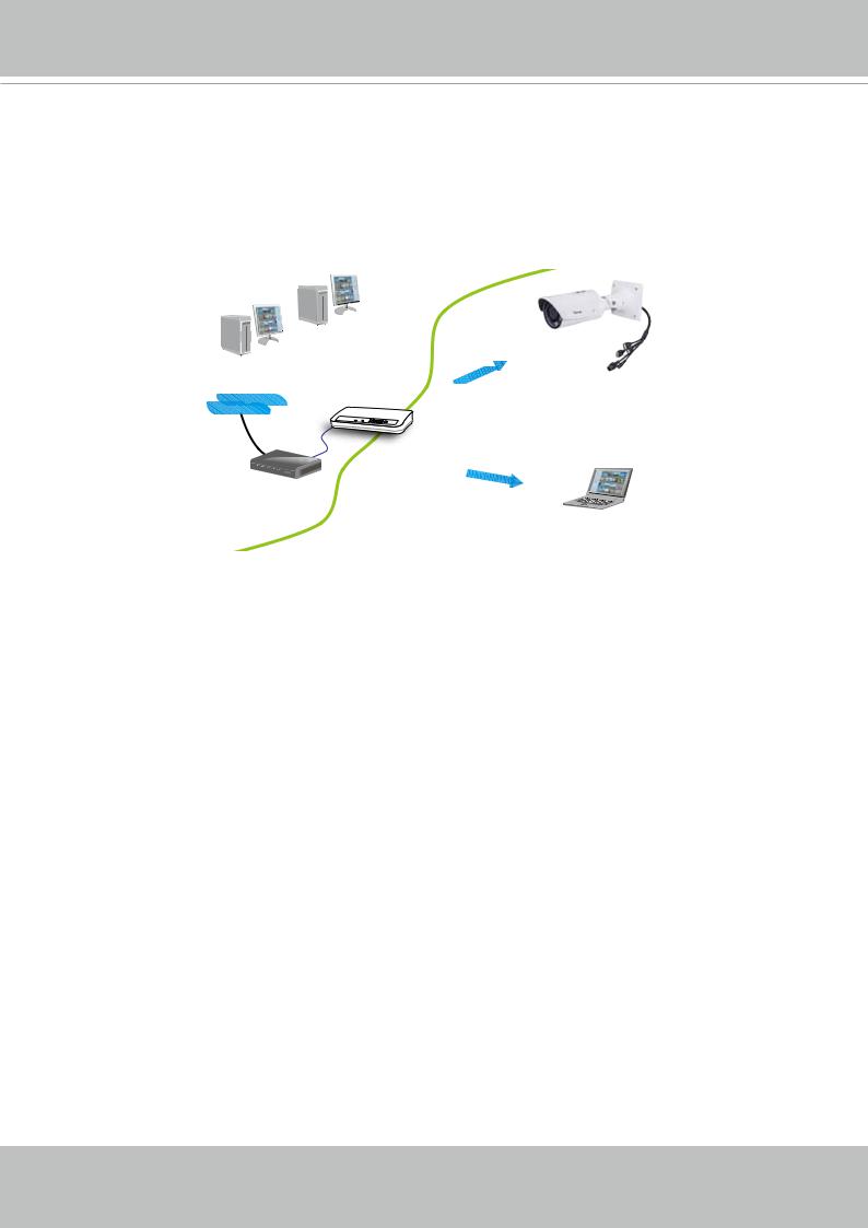
Internet connection via a router
Before setting up the Network Camera over the Internet, make sure you have a router and follow the steps below.
1.Connect your Network Camera behind a router, the Internet environment is illustrated below. Regarding how to obtain your IP address, please refer to Software Installation on page 20 for details.
Internet
WAN (Wide Area Network )
Router IP address : from ISP
LAN (Local Area Network)
Router IP address : 192.168.0.1
IP address : 192.168.0.3 Subnet mask : 255.255.255.0 Default router : 192.168.0.1
Cable or DSL Modem
IP address : 192.168.0.2
Subnet mask : 255.255.255.0
Default router : 192.168.0.1
2.In this case, if the Local Area Network (LAN) IP address of your Network Camera is 192.168.0.3, please forward the following ports for the Network Camera on the router.
■HTTP port: default is 80
■RTSP port: default is 554
■RTP port for video: default is 5556
■RTCP port for video: default is 5557
If you have changed the port numbers on the Network page, please open the ports accordingly on your router. For information on how to forward ports on the router, please refer to your router’s user’s manual.
3.Find out the public IP address of your router provided by your ISP (Internet Service Provider). Use the public IP and the secondary HTTP port to access the Network Camera from the
Internet. Please refer to Network Type on page 86 for details.
Internet connection with static IP
Choose this connection type if you are required to use a static IP for the Network Camera. Please refer to LAN setting on page 85 for details.
Internet connection via PPPoE (Point-to-Point over Ethernet)
Choose this connection type if you are connected to the Internet via a DSL Line. Please refer to PPPoE on page 86 for details.
28 - User's Manual
|
|
|
VIVOTEK |
|
|
|
|
|
|
|
|
|
|
|
For example, your router and IP settings may look like this: |
||||
|
Device |
IP Address: internal port |
IP Address: External Port (Mapped |
|
|
|
|
port on the router) |
|
|
Public IP of router |
122.146.57.120 |
|
|
|
LAN IP of router |
192.168.2.1 |
|
|
|
Camera 1 |
192.168.2.10:80 |
122.146.57.120:8000 |
|
|
Camera 2 |
192.168.2.11:80 |
122.146.57.120:8001 |
|
|
... |
... |
... |
|
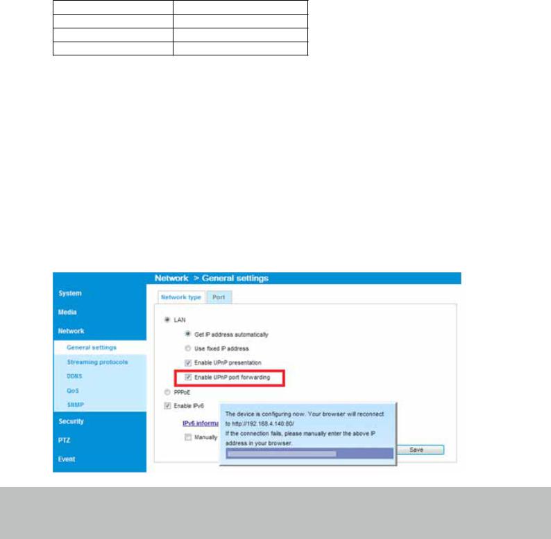
Configure the router, virtual server or firewall, so that the router can forward any data coming into a preconfigured port number to a network camera on the private network, and allow data from the camera to be transmitted to the outside of the network over the same path.
From |
Forward to |
122.146.57.120:8000 |
192.168.2.10:80 |
122.146.57.120:8001 |
192.168.2.11:80 |
... |
... |
When properly configured, you can access a camera behind the router using the HTTP request as follows: http://122.146.57.120:8000
If you change the port numbers on the Network configuration page, please open the ports accordingly on your router. For example, you can open a management session with your router to configure access through the router to the camera within your local network.
Please consult your network administrator for router configuration if you have troubles with the configuration.
For more information with network configuration options (such as that of streaming ports), please refer to Configuration > Network Settings. VIVOTEK also provides the automatic port forwarding feature as an NAT traversal function with the precondition that your router must support the UPnP port forwarding feature.
User's Manual - 29
VIVOTEK
Accessing the Network Camera
This chapter explains how to access the Network Camera through web browsers, RTSP players,
3GPP-compatible mobile devices, and VIVOTEK recording software.
Using Web Browsers
Use Installation Wizard 2 (IW2) to access the Network Cameras on LAN.
If your network environment is not a LAN, follow these steps to access the Netwotk Camera:
1.Launch your web browser (e.g., Microsoft® Internet Explorer or Mozilla Firefox).
2.Enter the IP address of the Network Camera in the address field. Press Enter.
3.Live video will be displayed in your web browser.
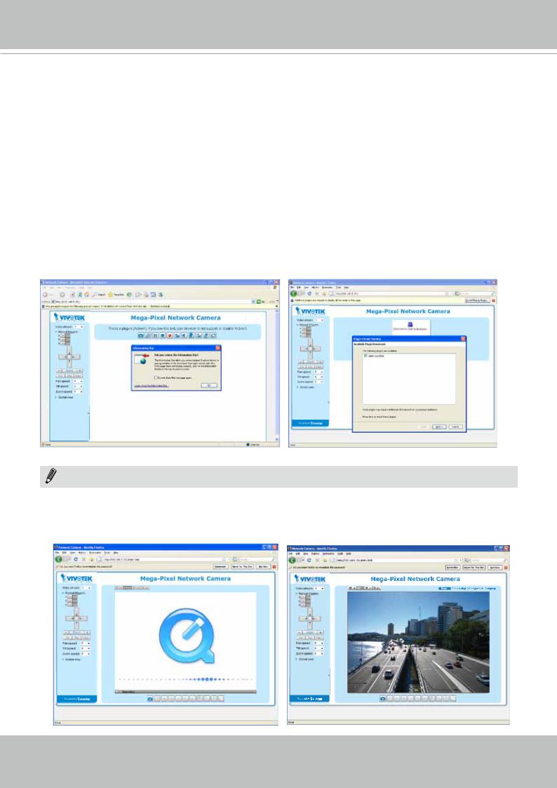
4.If it is the first time installing the VIVOTEK network camera, an information bar will prompt as shown below. Follow the instructions to install the required plug-in on your computer.
NOTENOTE:
► For Mozilla Firefox or Chrome users, your browser will use QuickTime to stream the live video. If you don’t have QuickTime on your computer, please download it first, then launch the web browser.
30 - User's Manual
Loading...